When you click on links to various merchants on this site and make a purchase, this can result in this site earning a commission. Affiliate programs and affiliations include, but are not limited to, the eBay Partner Network.
I am a station wagon guy. I love the utility and that a station wagon drives like the car it is. Along with that, I am not a truck owner. When I occasionally have to haul something that is either large or dirty, I prefer to use a small utility trailer. Over the years I have installed a number of hitches on various cars and wagons. It was time for the Allroad to be hitched!!
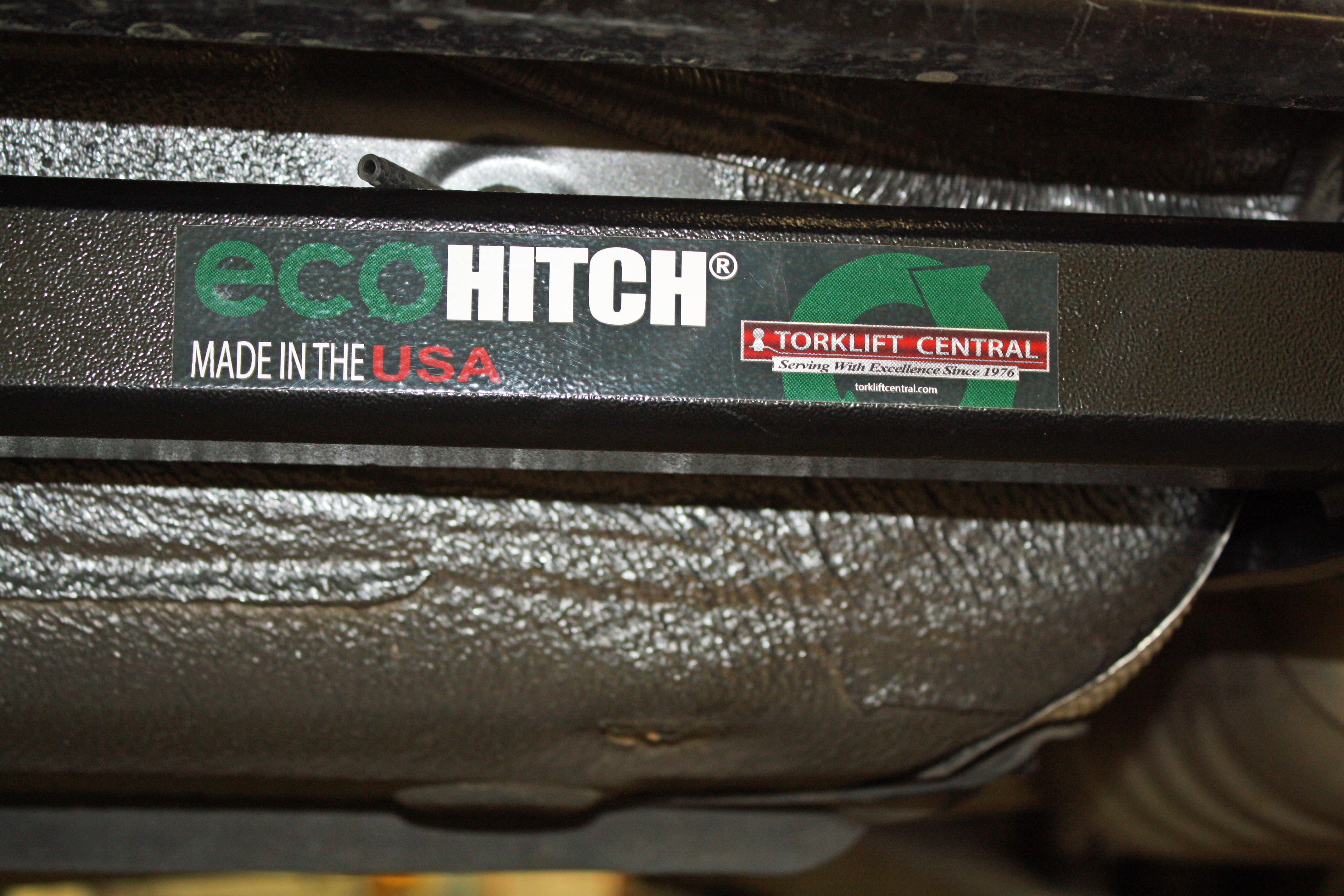
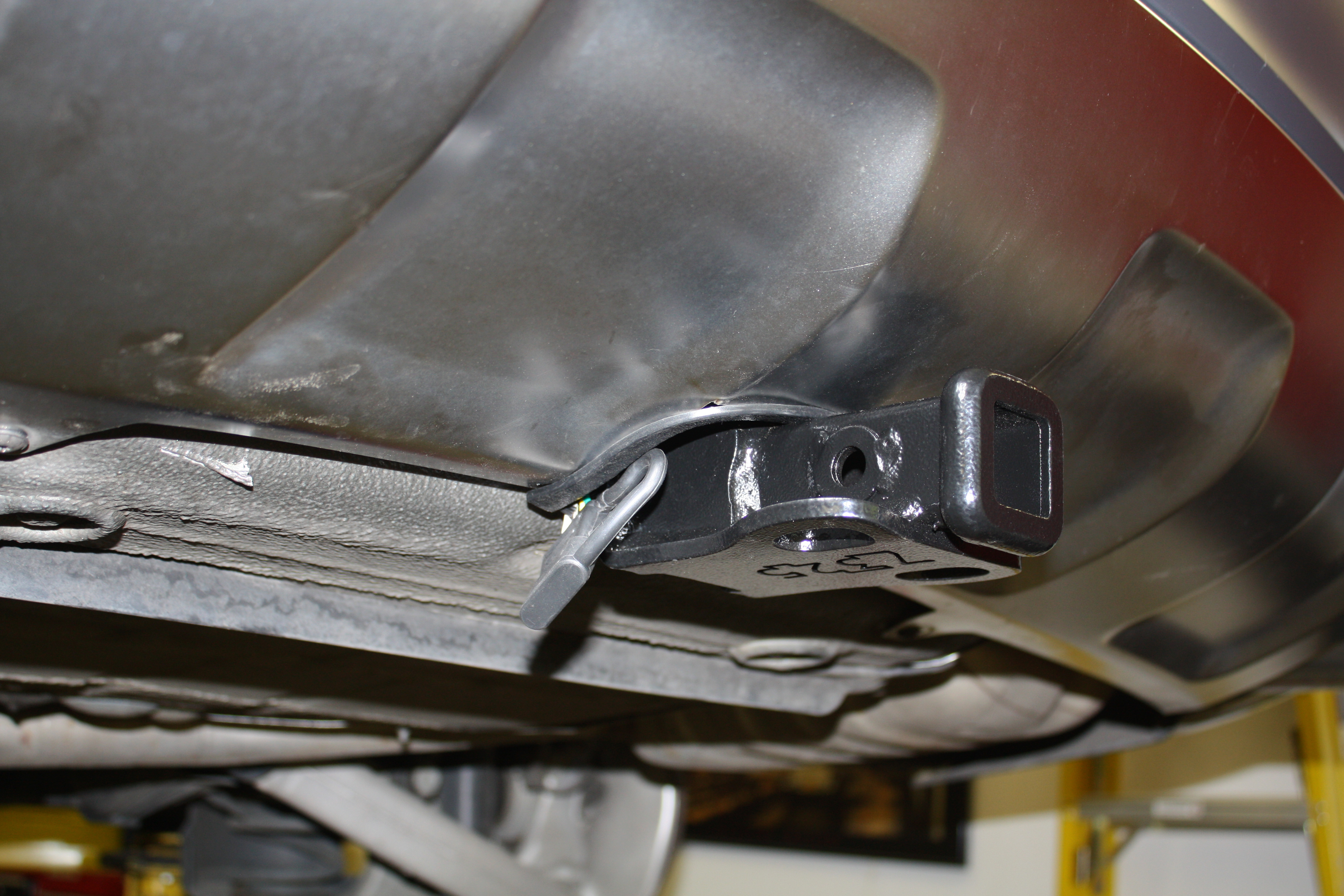
My hitch of choice has been Curt. They are well made and priced well. My biggest beef with them is that they hang low and are exposed. On my last hitch installation, a 2010 Cadillac CTS wagon, the hitch would often drag when traversing dips. During my search for a hitch for the Allroad, I came across the Ecohitch by Torklift Central. I watched their installation video and loved the fact that the hitch is mostly hidden. In spite of costing nearly double the price of a Curt, I ordered one.
Like the Curt, the hitch was powder coated. The Ecohitch had a textured appearance and appears to be well made. The written instructions were very good with some small photos.
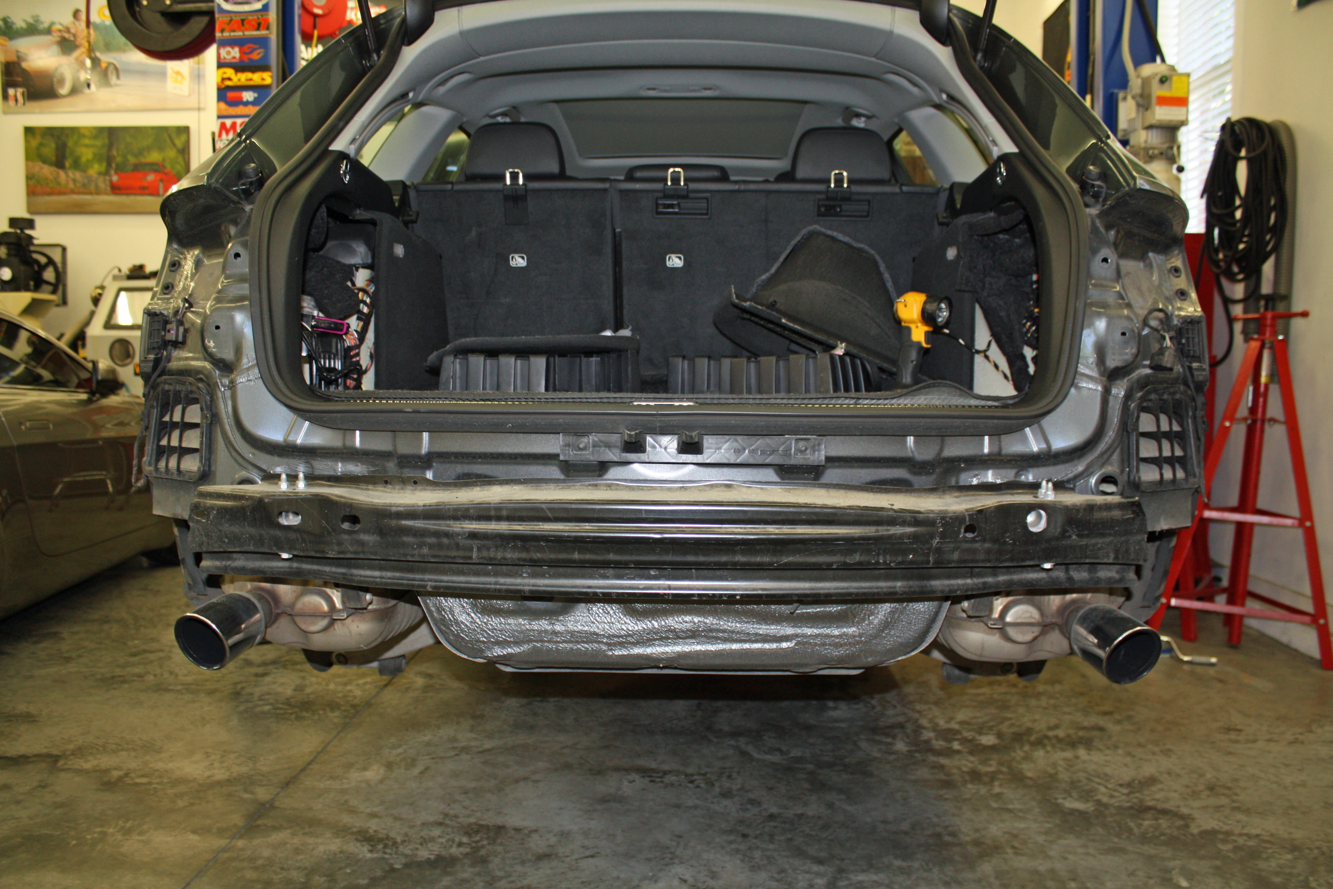
The first instruction says to raise the rear of the vehicle. Having a lift in my garage made that an easy task. (Increasing garage envy would be that my garage has AC, kind of important in August in North Carolina. Seventy-five degrees and little humidity inside the garage.) Having read the instructions ahead of time, I knew that removing the rear wheels would help.
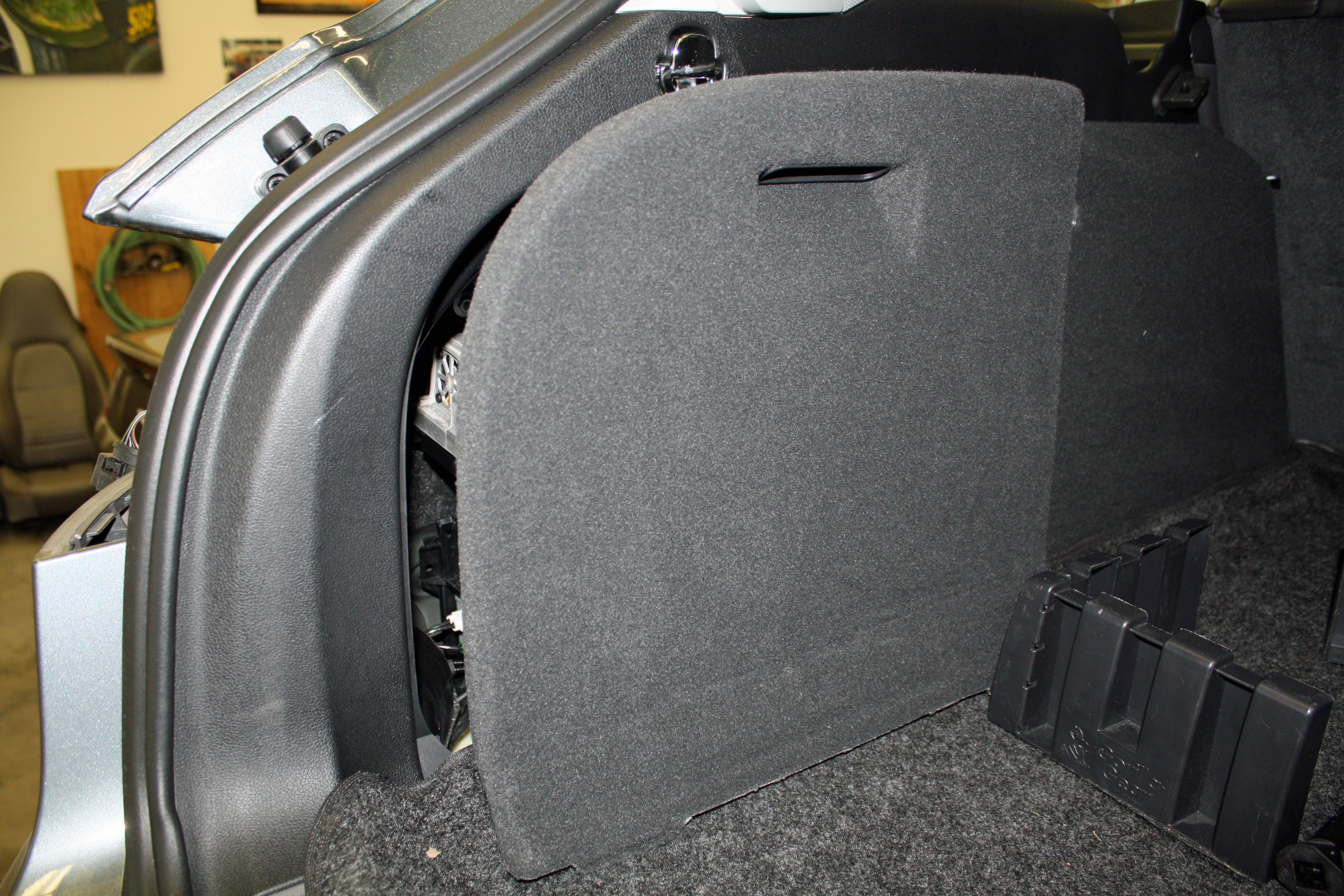
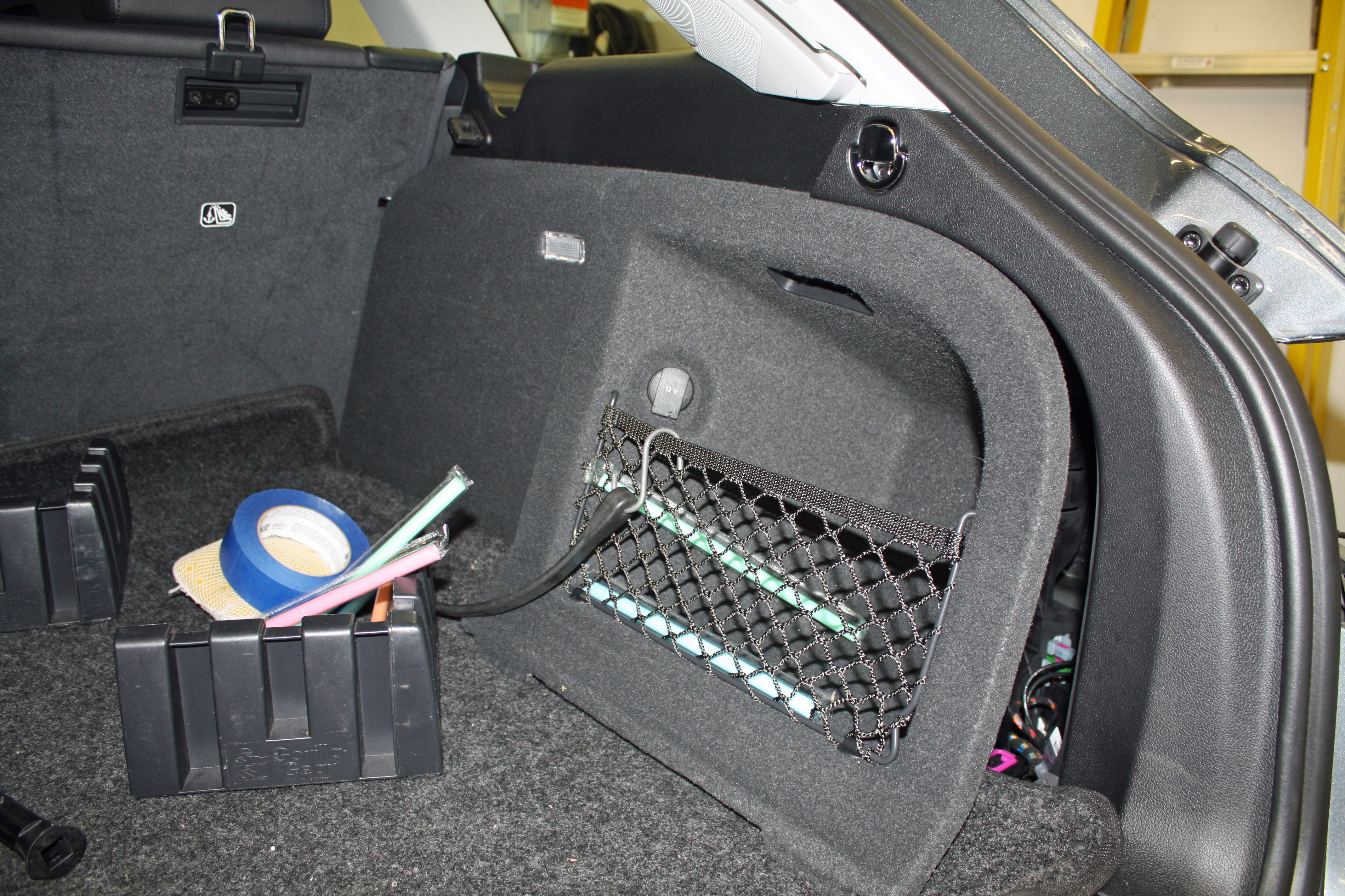
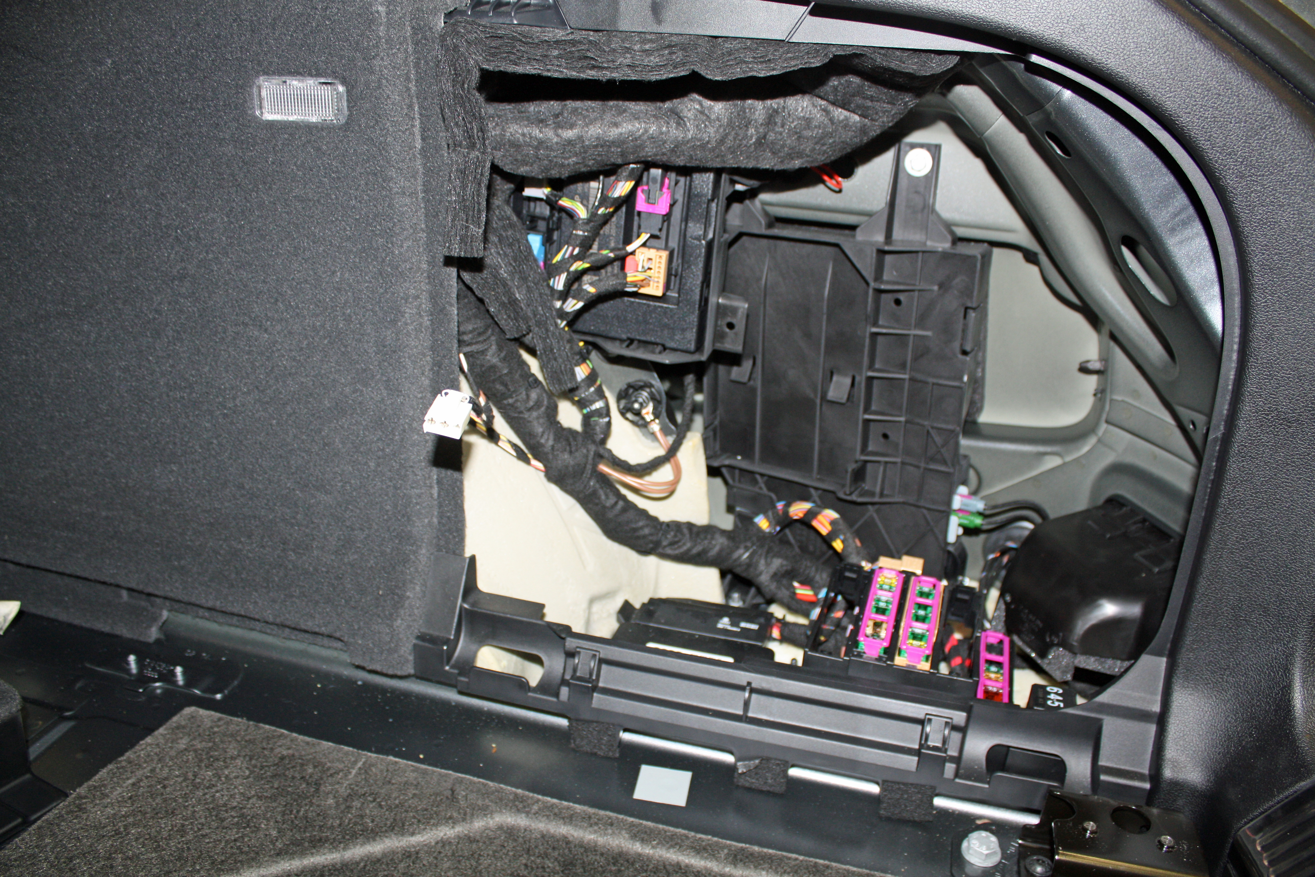
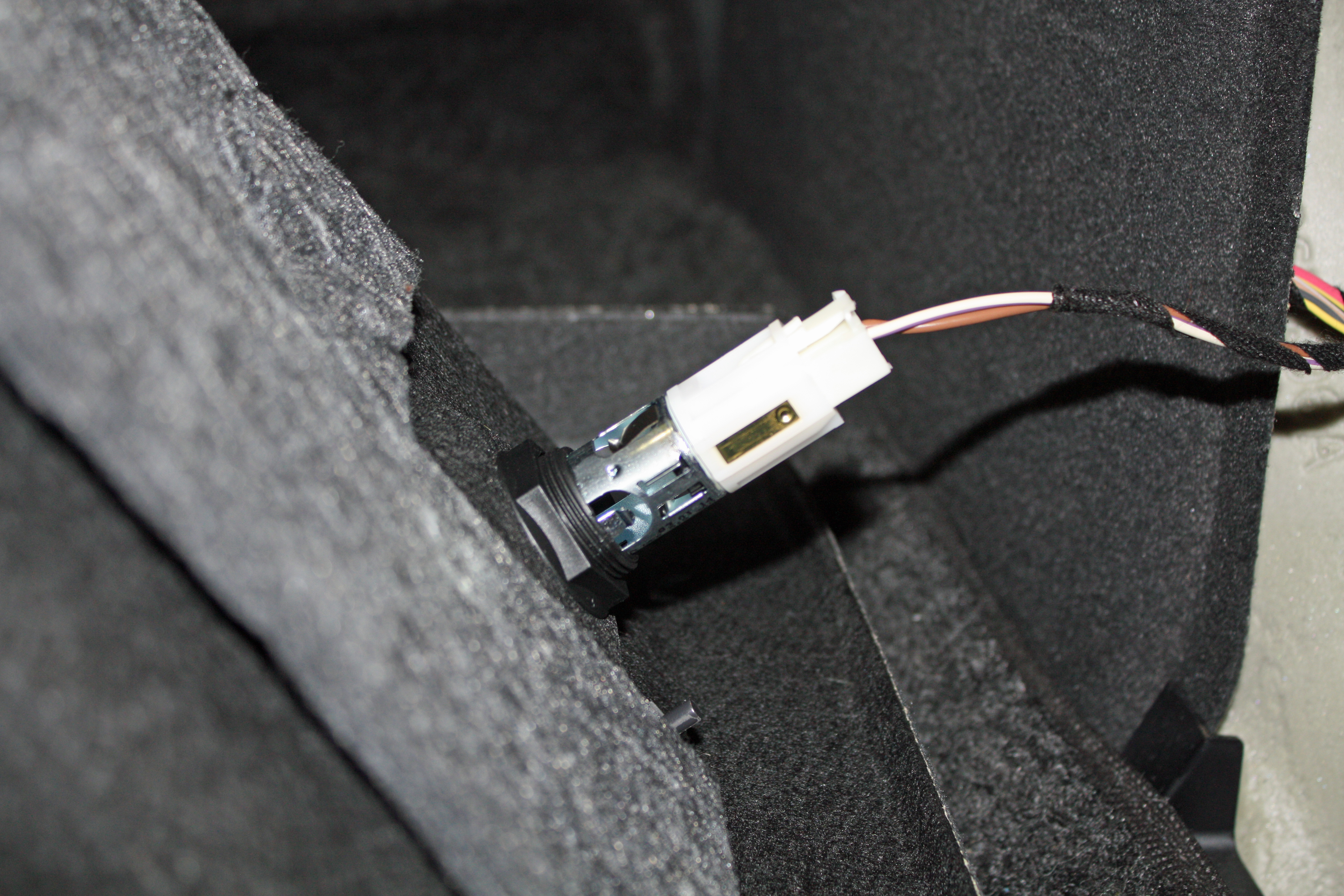
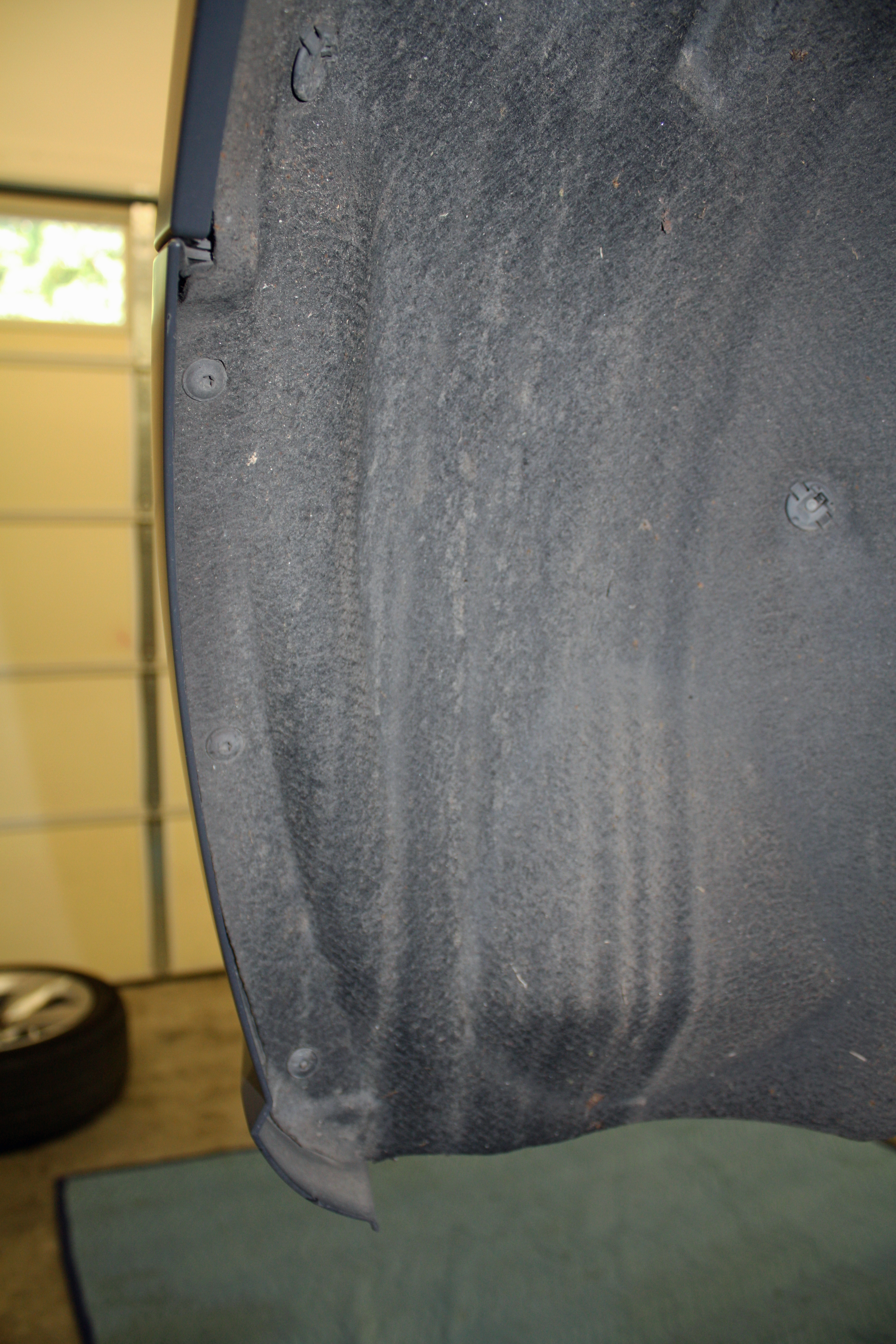
Next up is removing the side panels on each side of the rear cargo area. The passenger side has a 12V outlet that has to be unplugged before you can move the panel completely out of the way.
The back up sensor plug must be undone and the pigtail to the rear bumper cover pushed through the access hole.
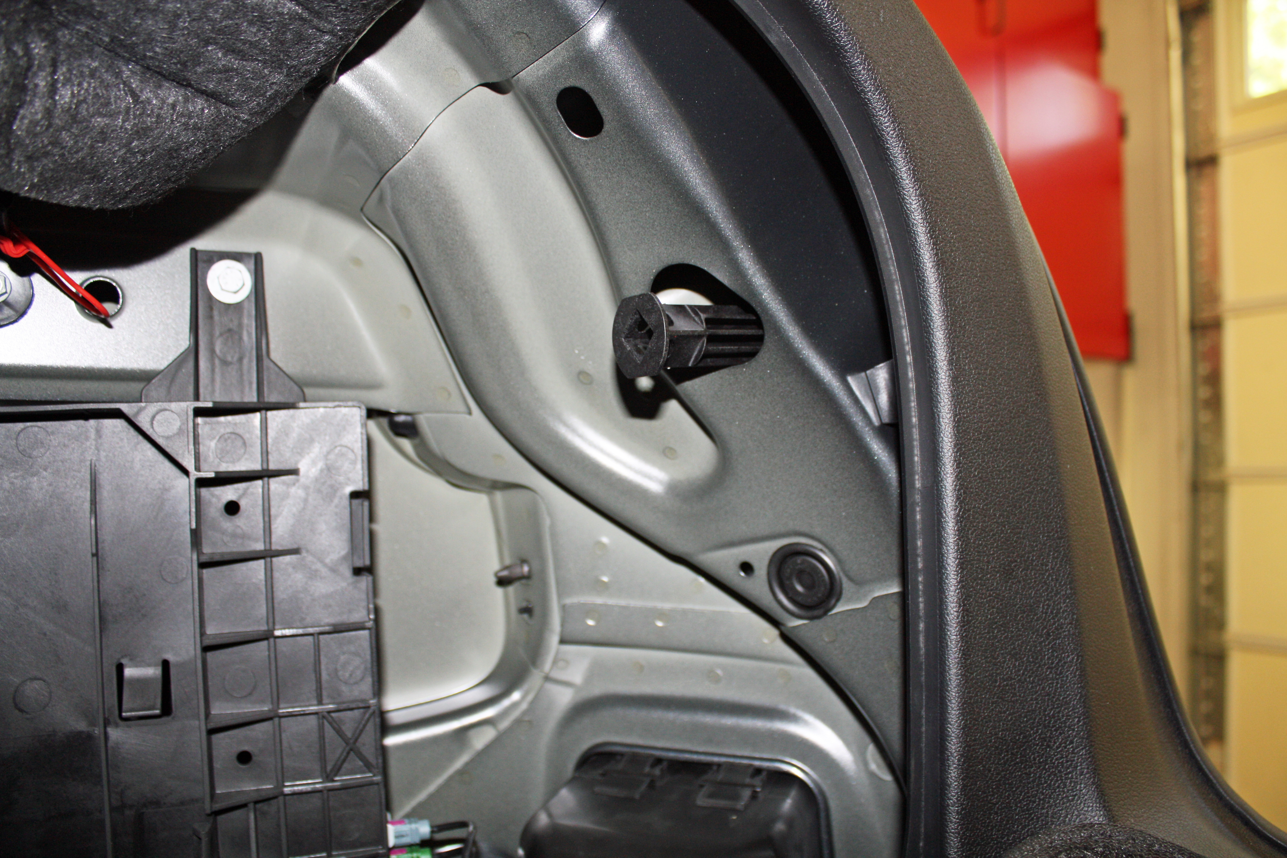
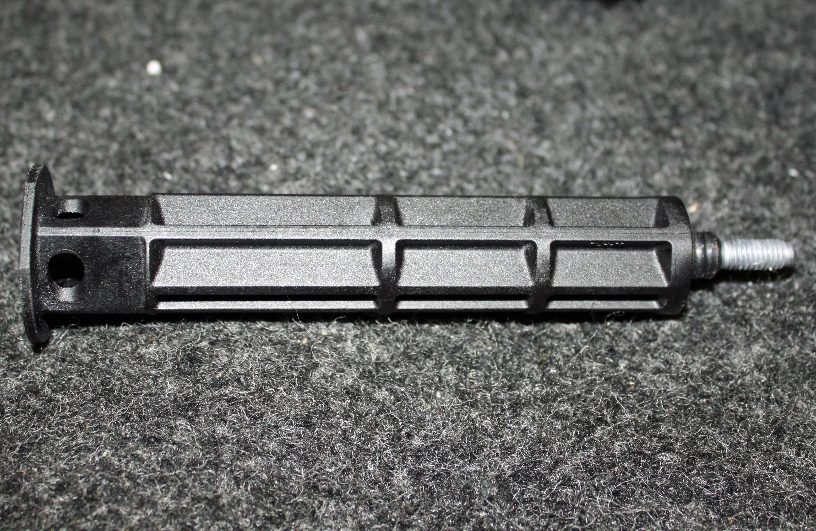
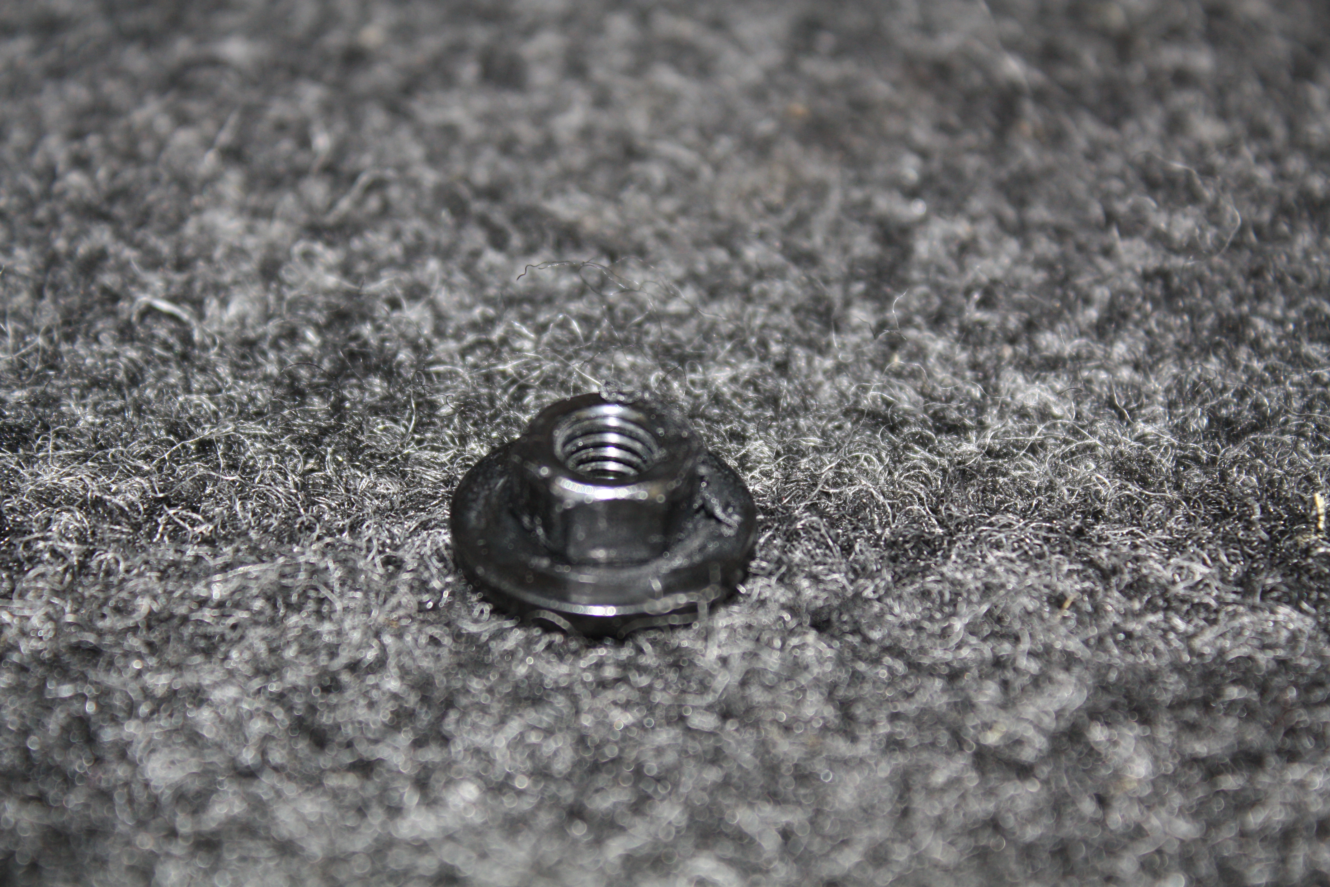
To remove the taillights, a large black pin must be unscrewed. Just below that pin is a rubber grommet. Once that grommet is removed, a 10mm hex nut will be found that attaches to the rear bumper.
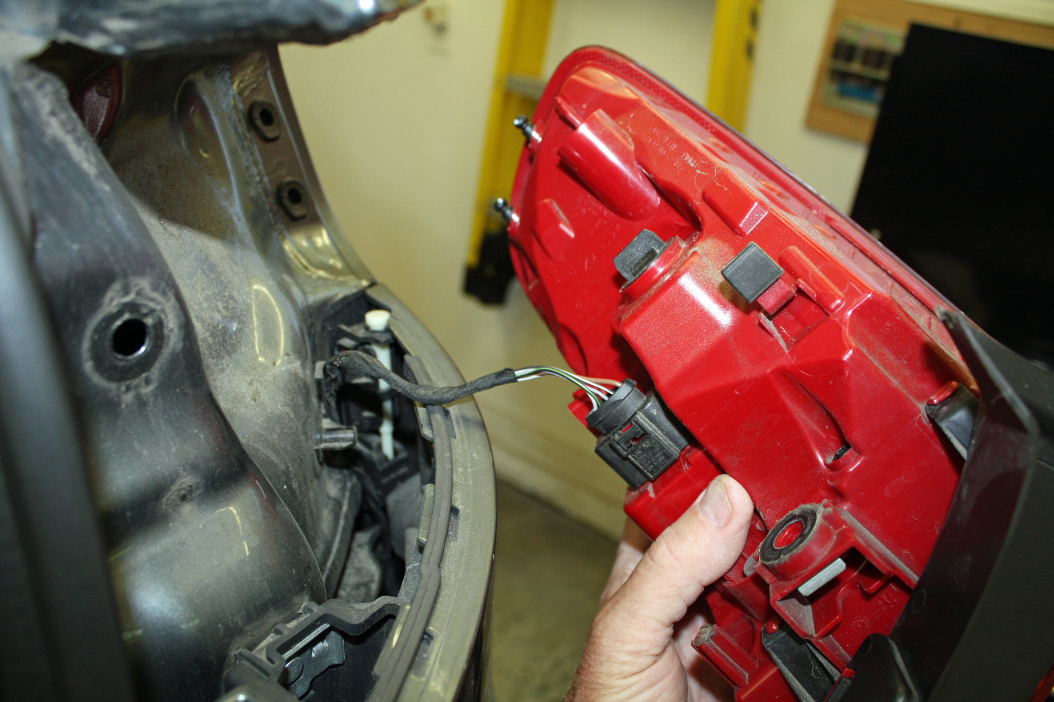
The taillights are located by two pins on the front edge. Push the taillight to the rear to dis-engage the pins and then remove the electrical connector.
There will be three torx screws in each rear wheel well that attach the inner fender liner to the rear bumper cap. Remove them and a fastener above them that slides off by applying a screwdriver to one side. Underneath the rear bumper cap will be found three more screws that need to be removed.
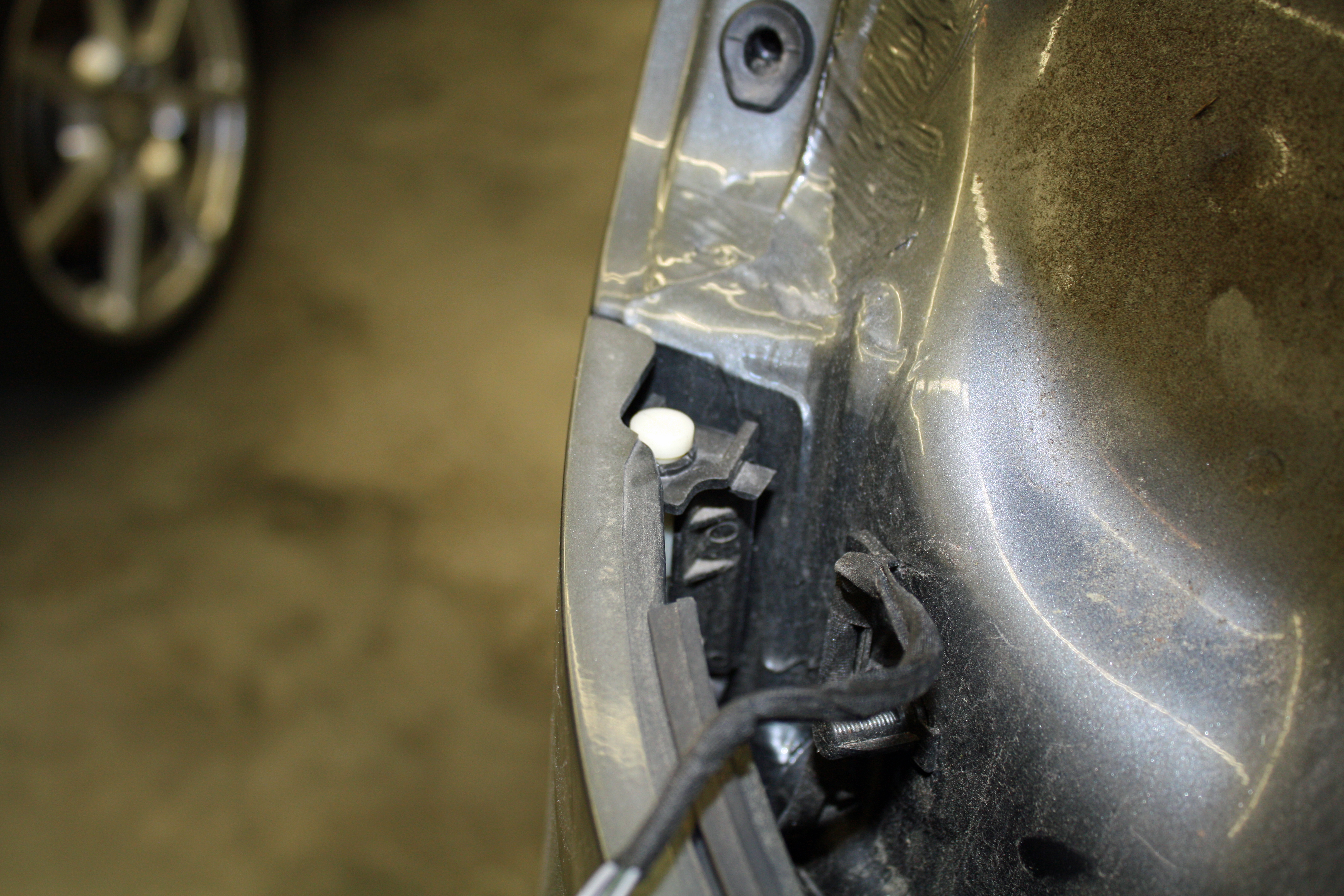
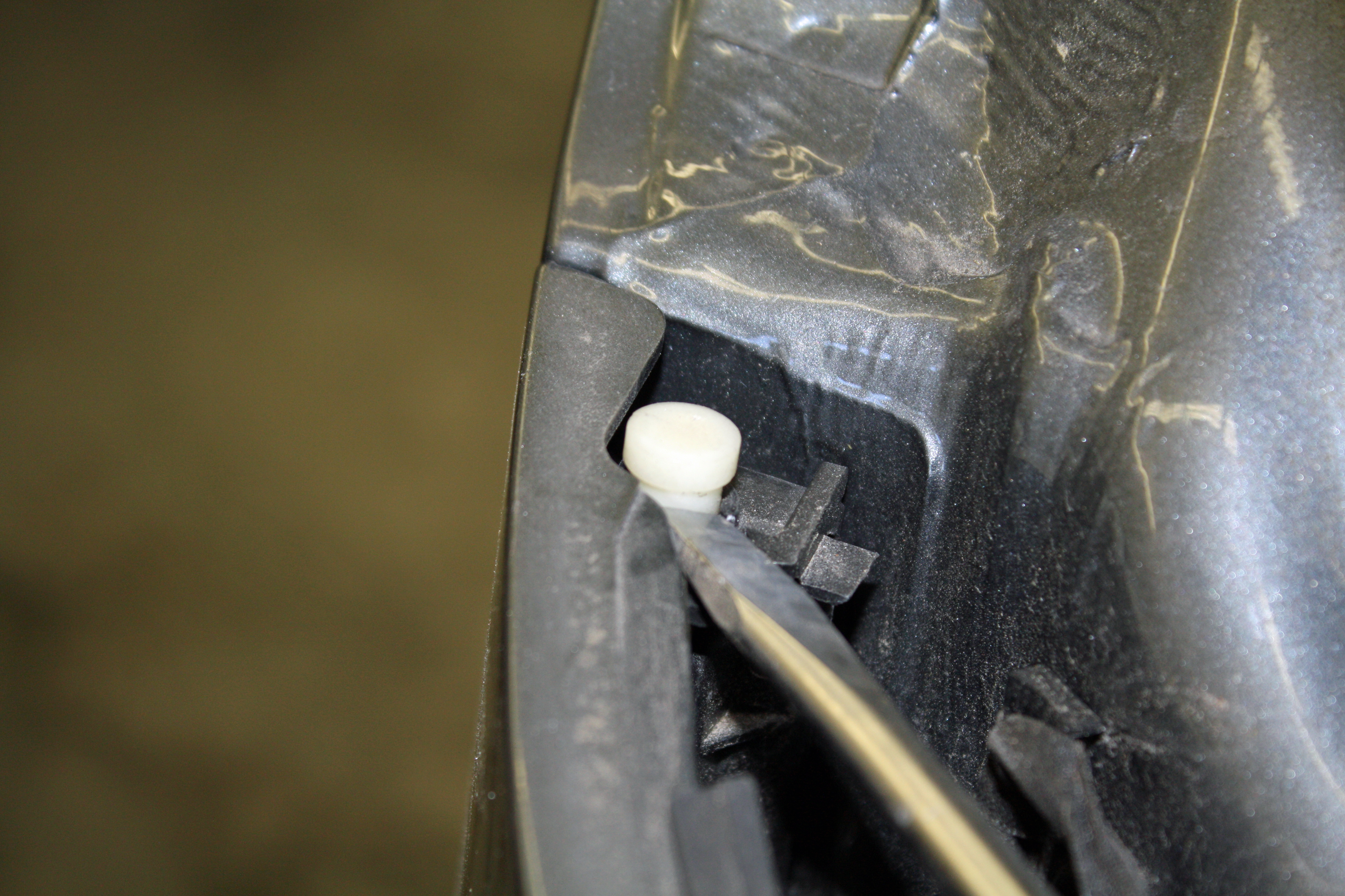
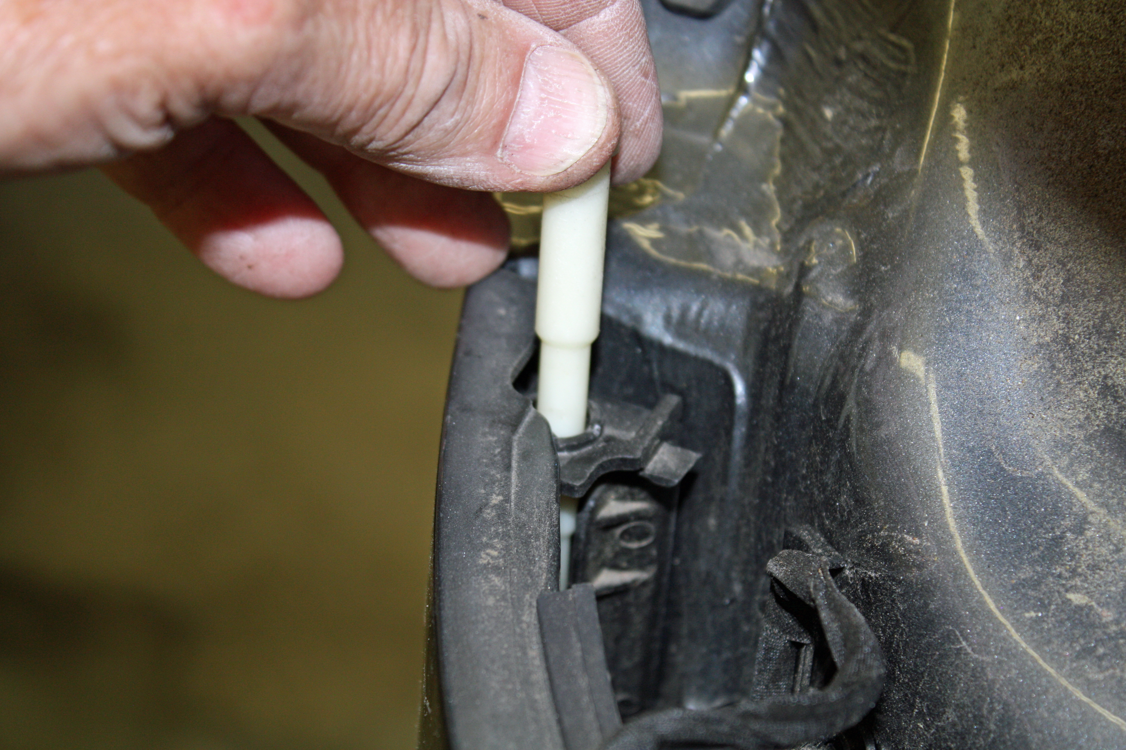
In the taillight opening will be found a white guide pin. Pry this pin up and then release the guide pin hinge by pushing it towards the center of the car. This releases the bumper cap from the body.
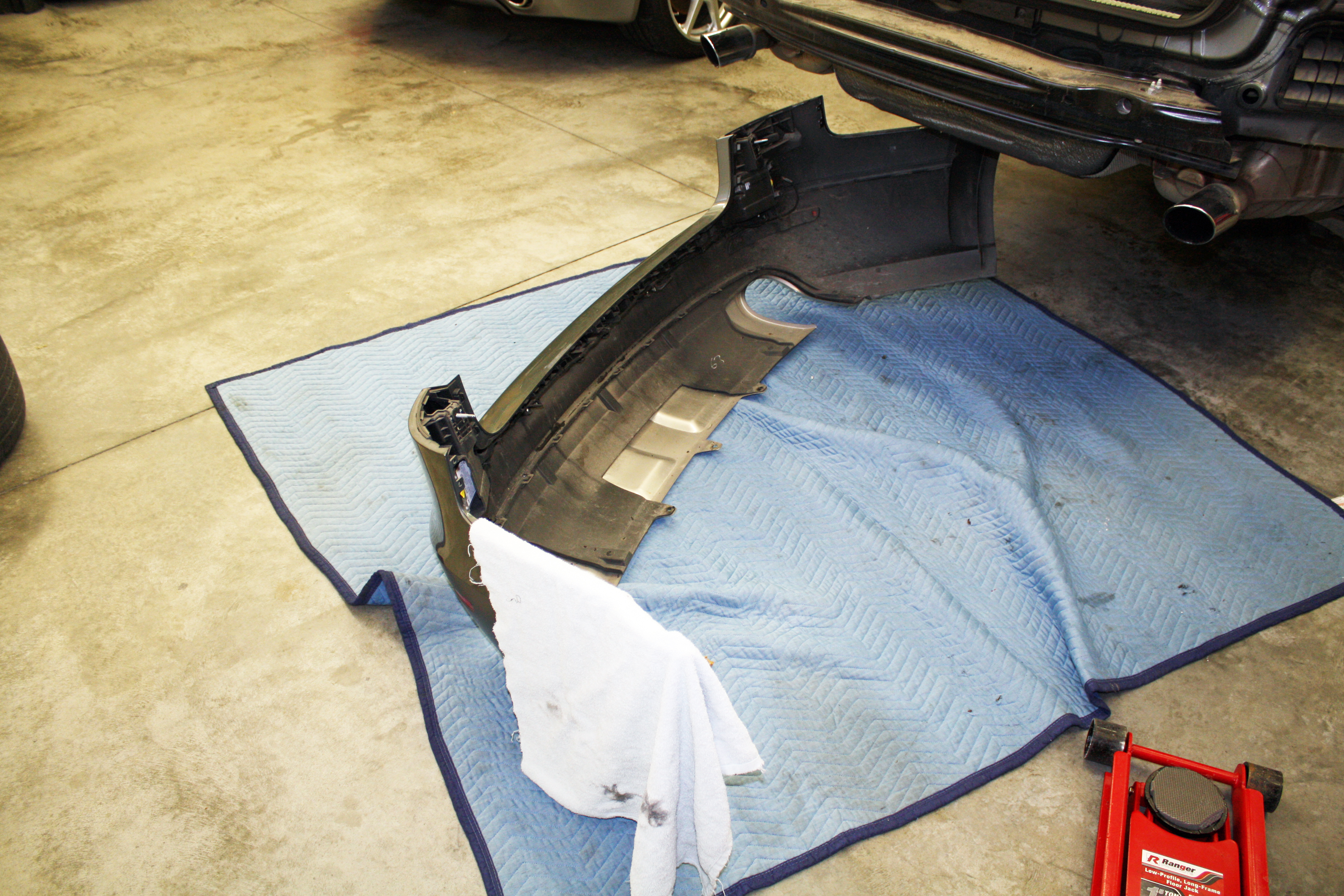
Gently unsnap and remove the rear bumper cap starting at the wheel well corners while working your way towards the center. It comes off fairly easily at this point. Keep in mind the pigtail for the back up sensors on the passenger side.
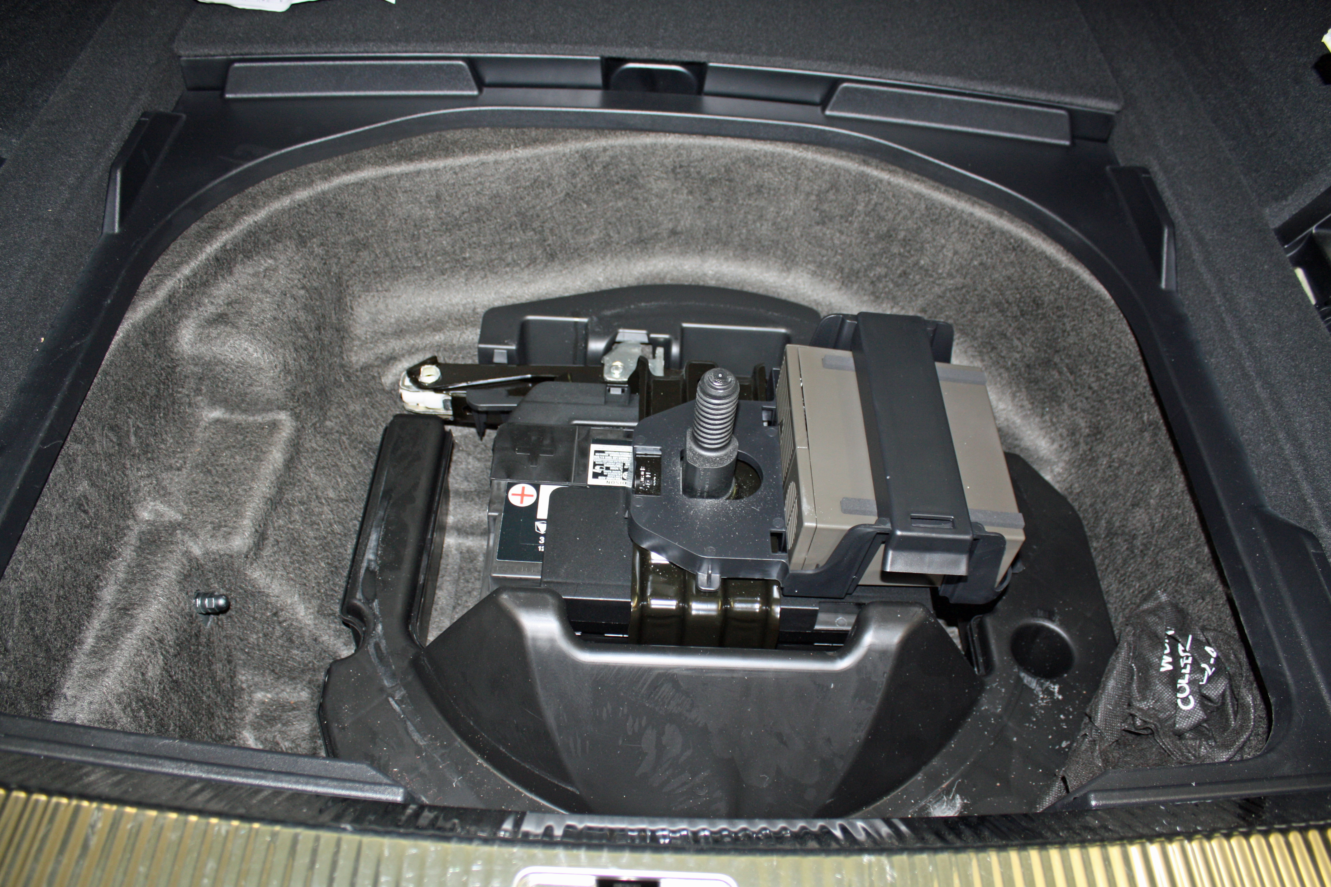
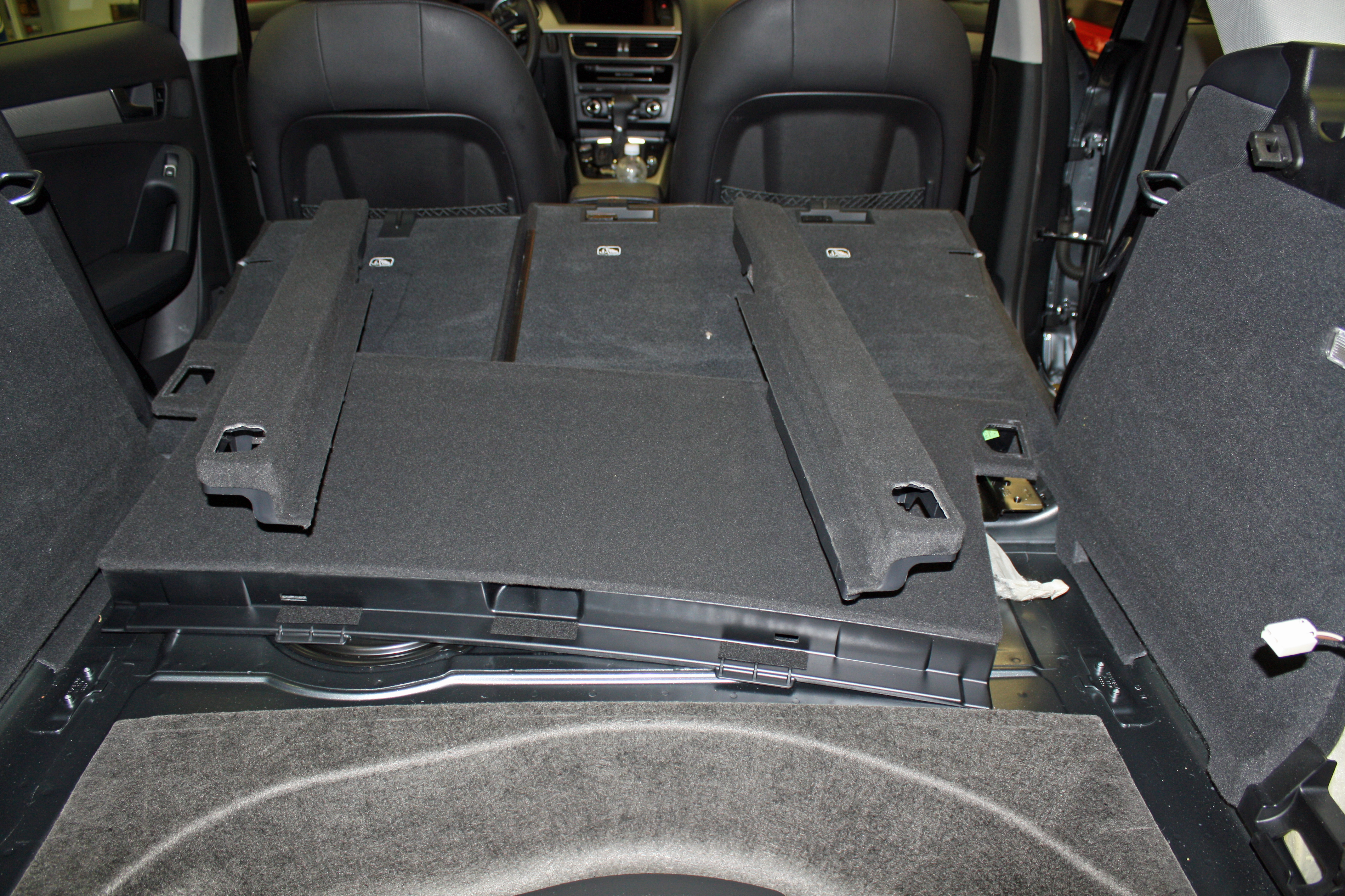
Remove the spare tire. With it out of the way, remove the plastic liner around the spare tire opening. There are four torx screws on the rear ledge.
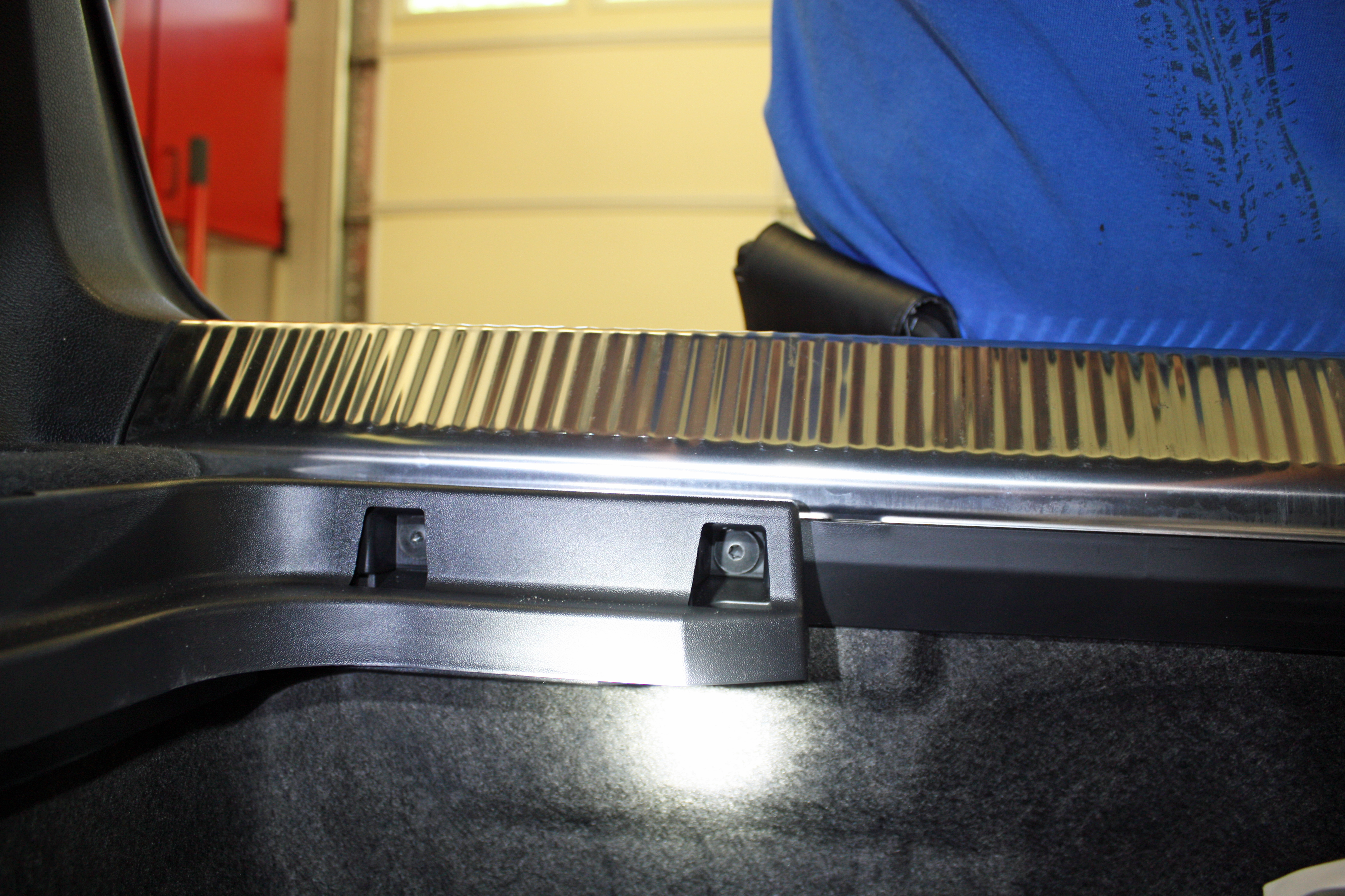
Remove the four cargo tie downs and lift off the two side rails. This exposes a bolt on each side that will be used later on.
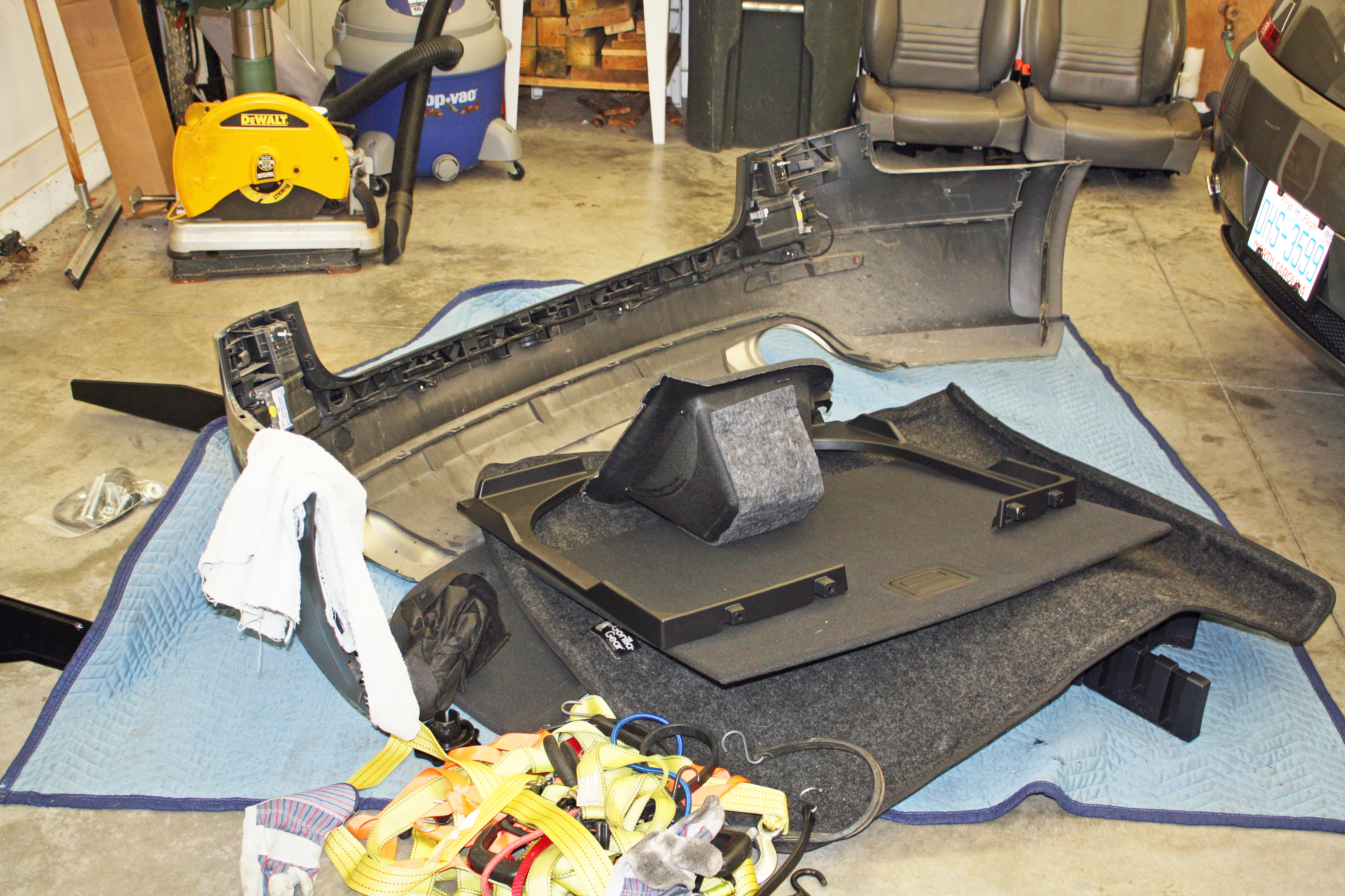
And the pile is growing.
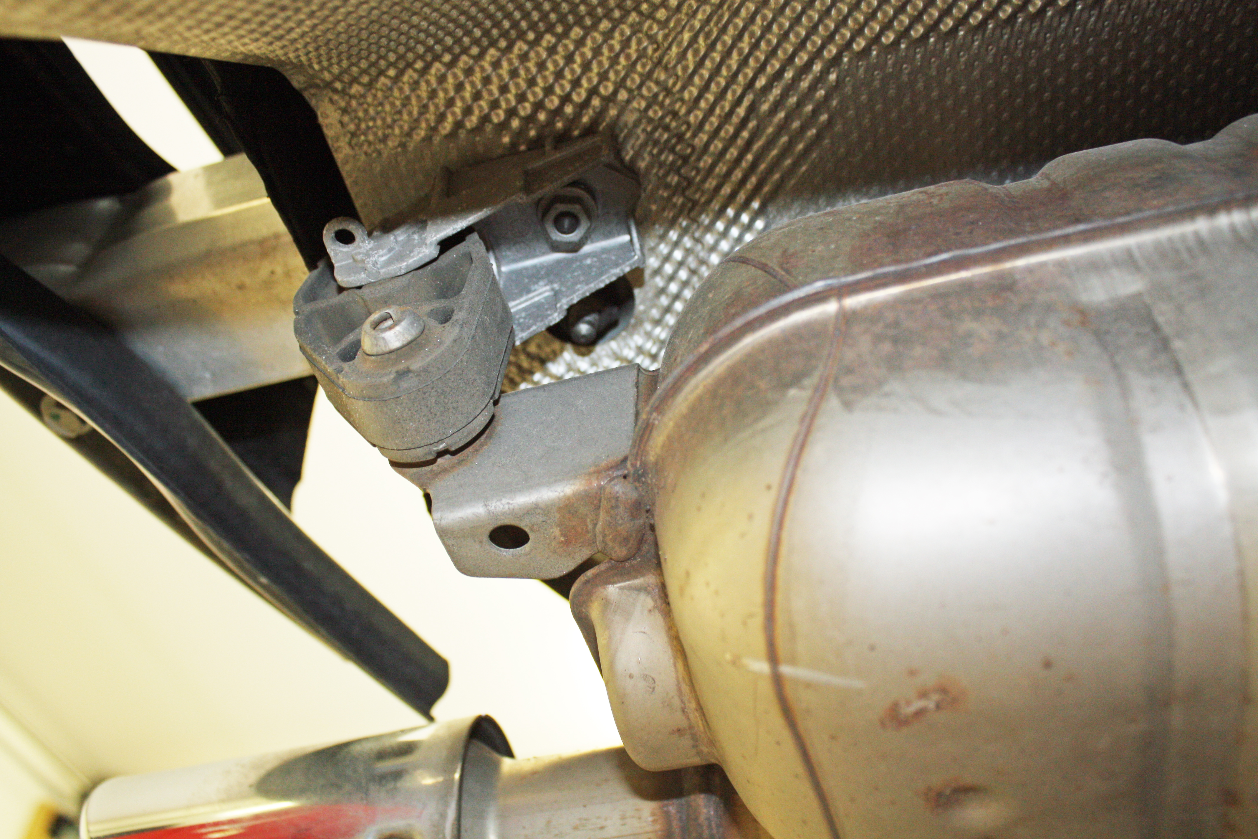
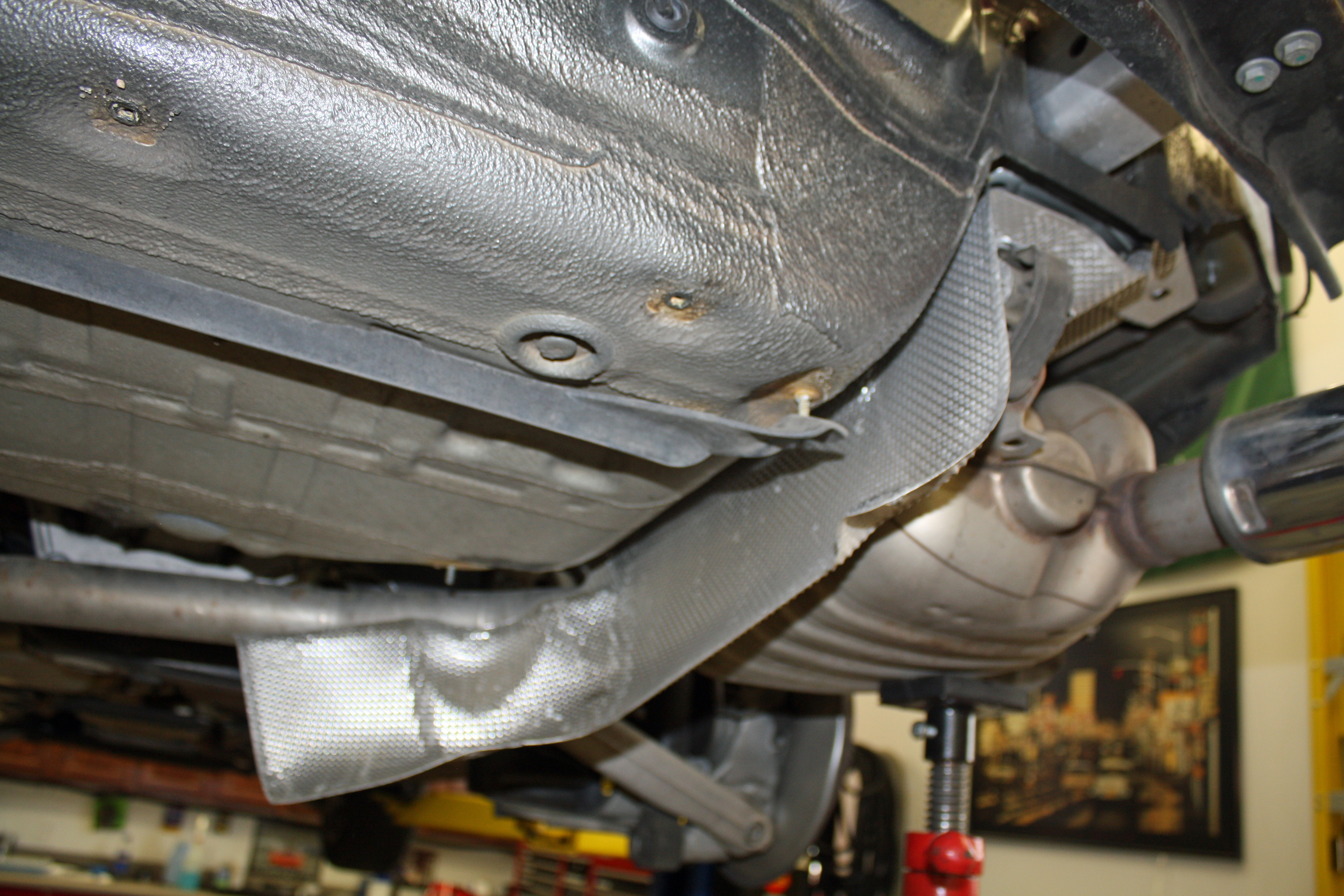
Remove the 10mm nut that attached the rear exhaust hanger after supporting the mufflers.
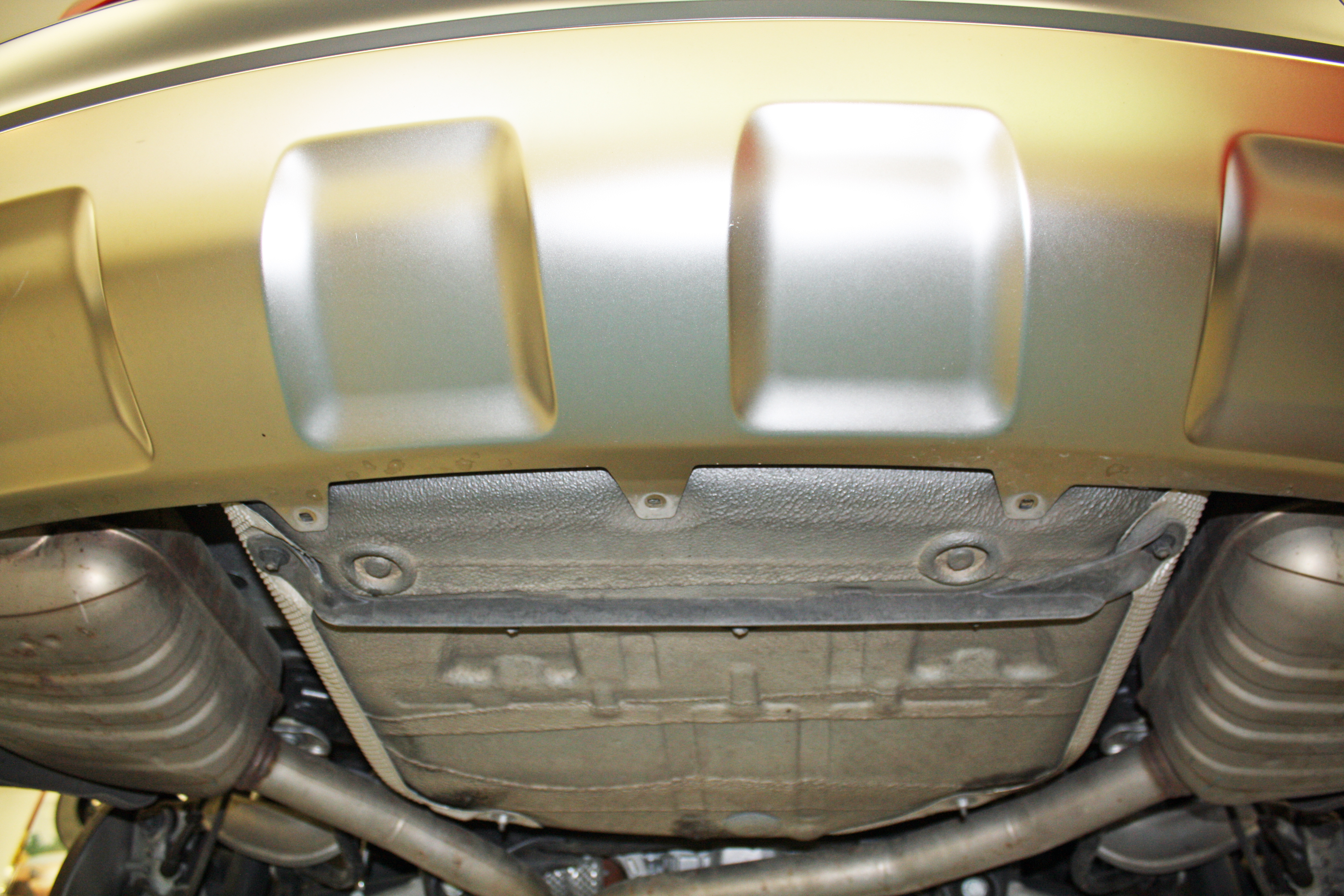
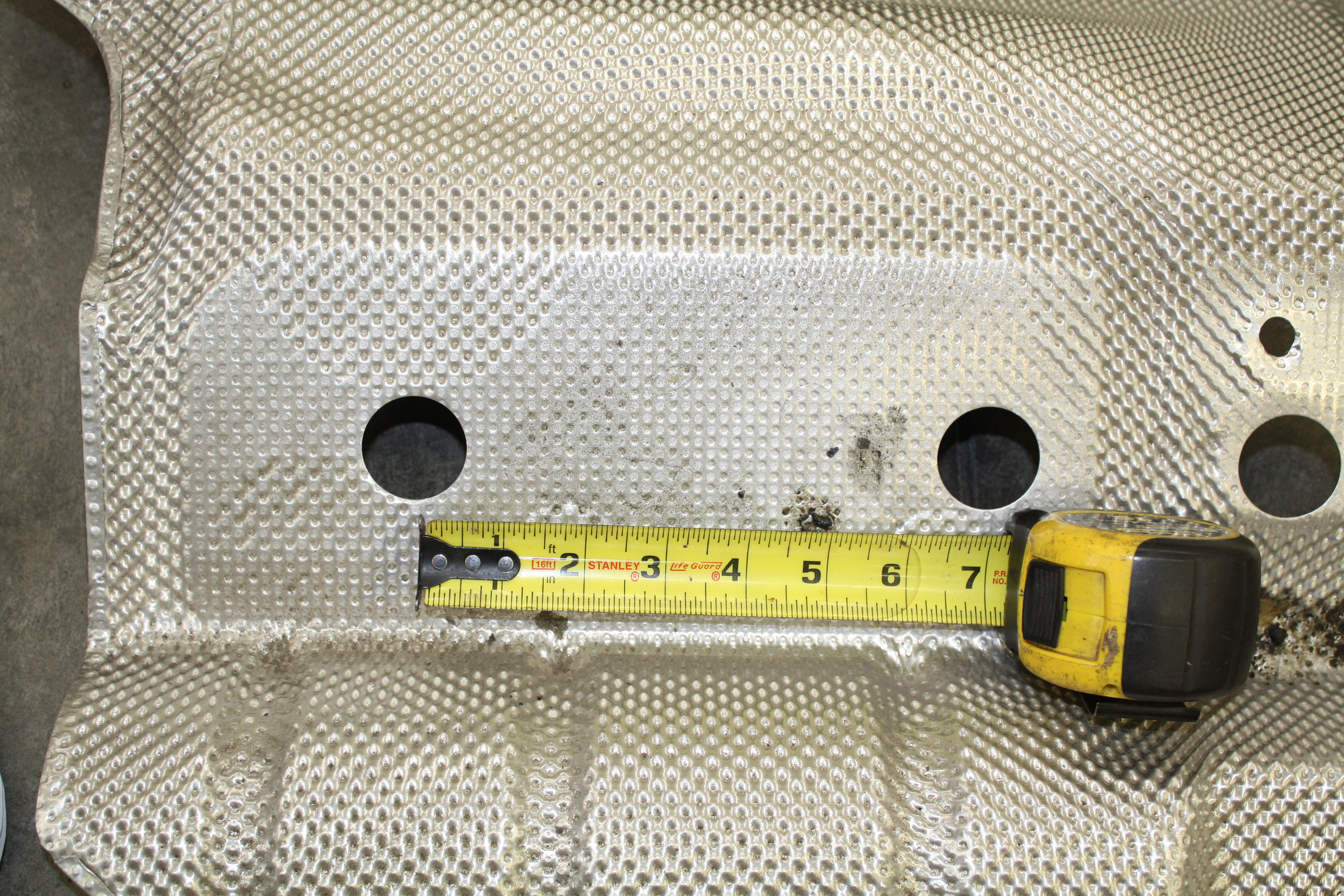
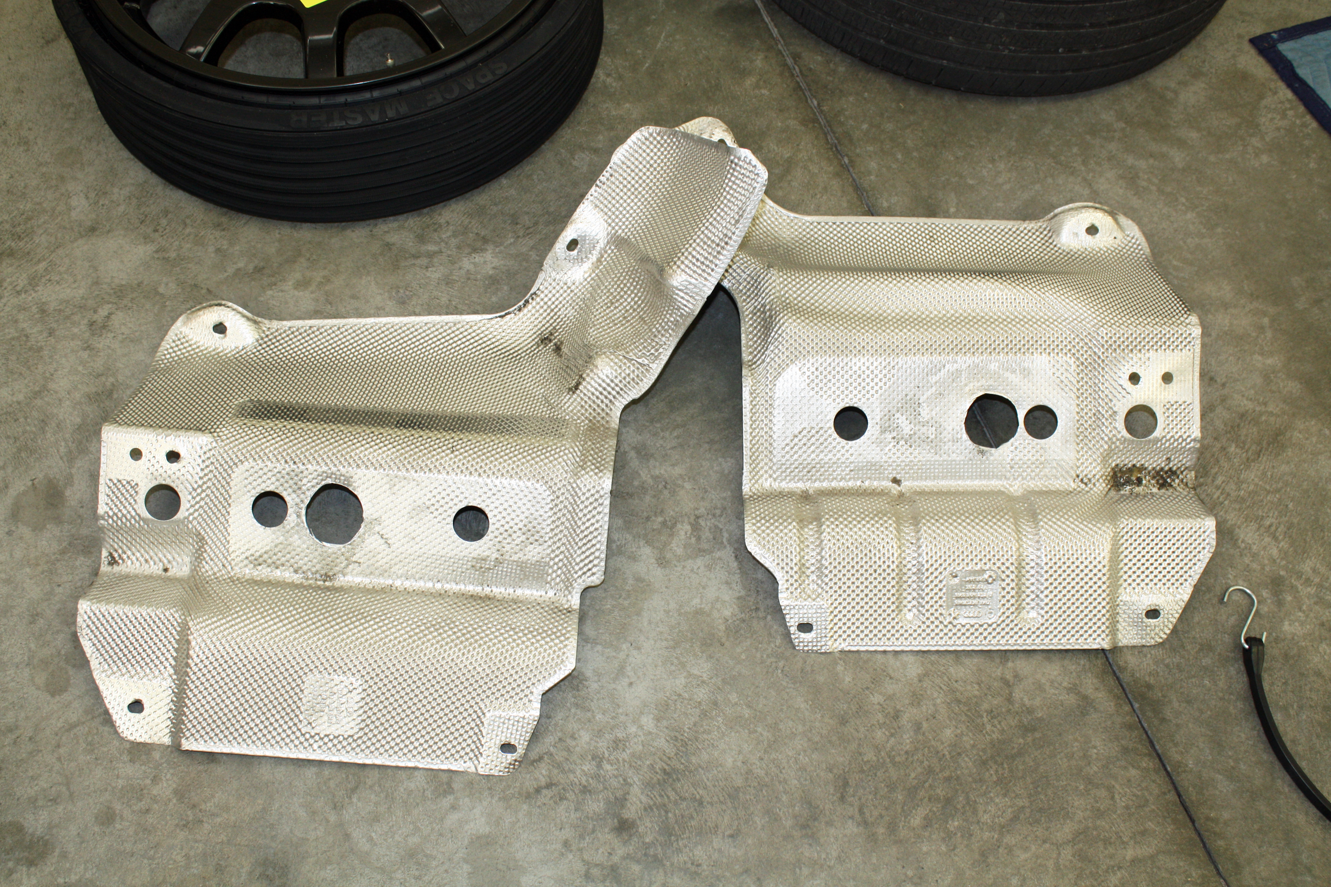
Now the heat shields can be removed. Once they are off the car, a two inch hole needs to be cut into each of them. Mark a point five inches from the center of the forward most hole to the center of the new hole.
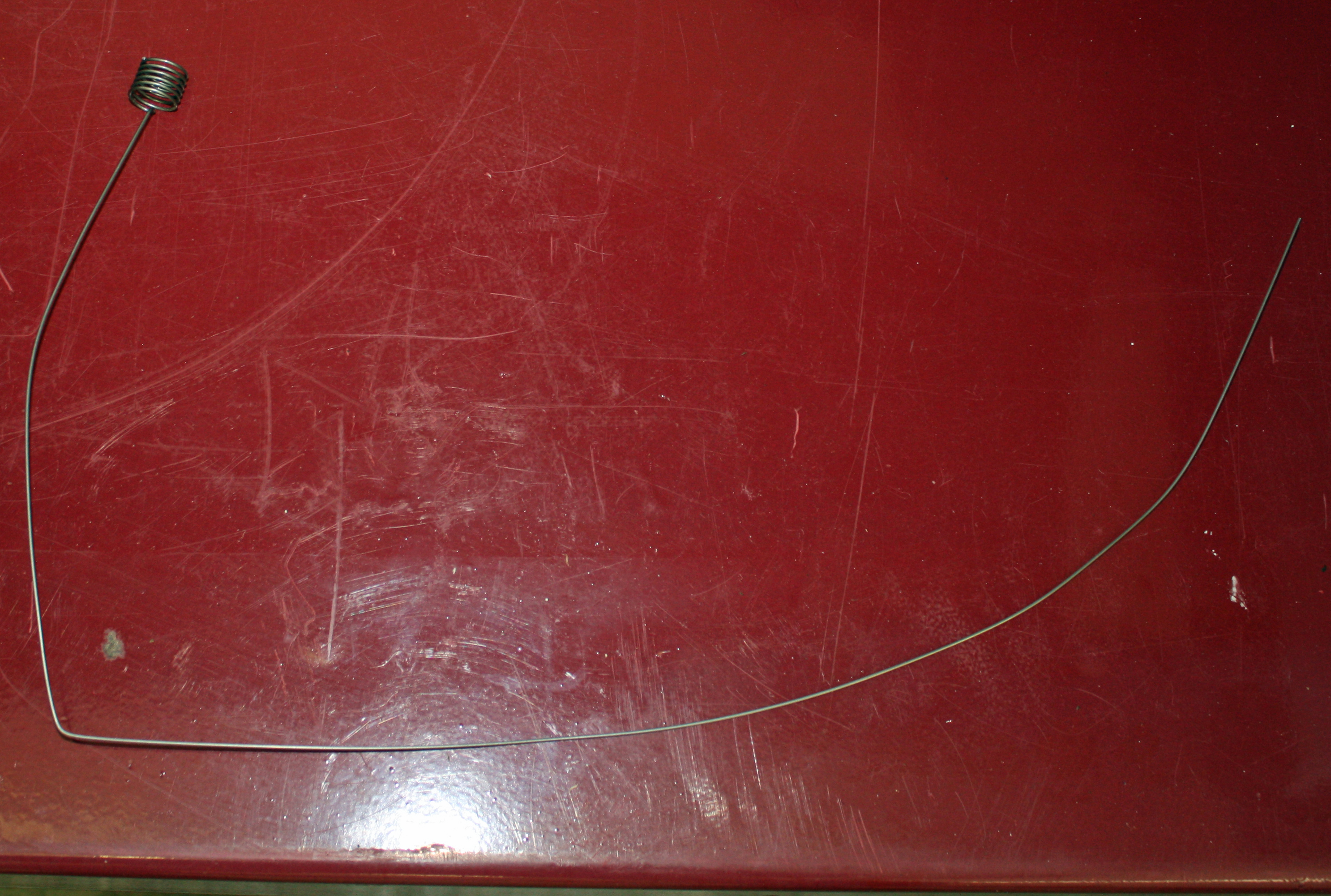
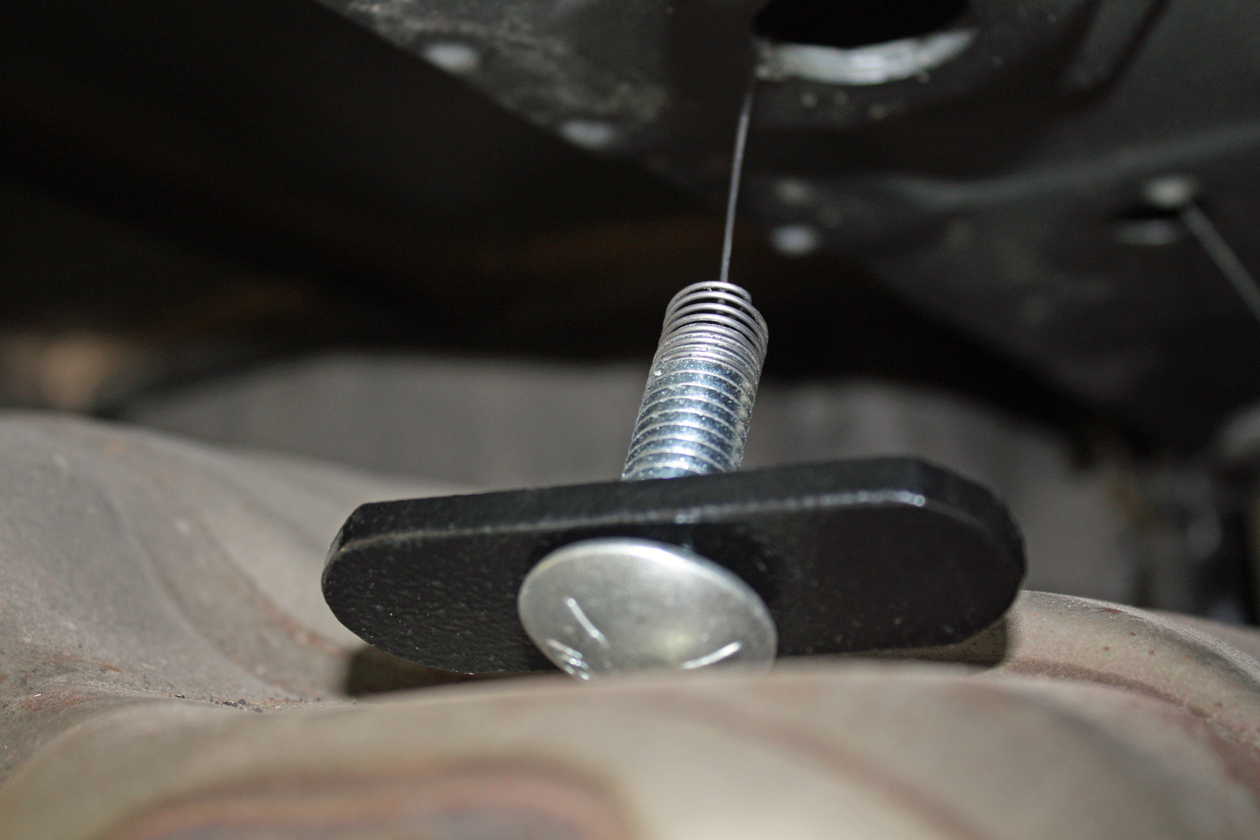
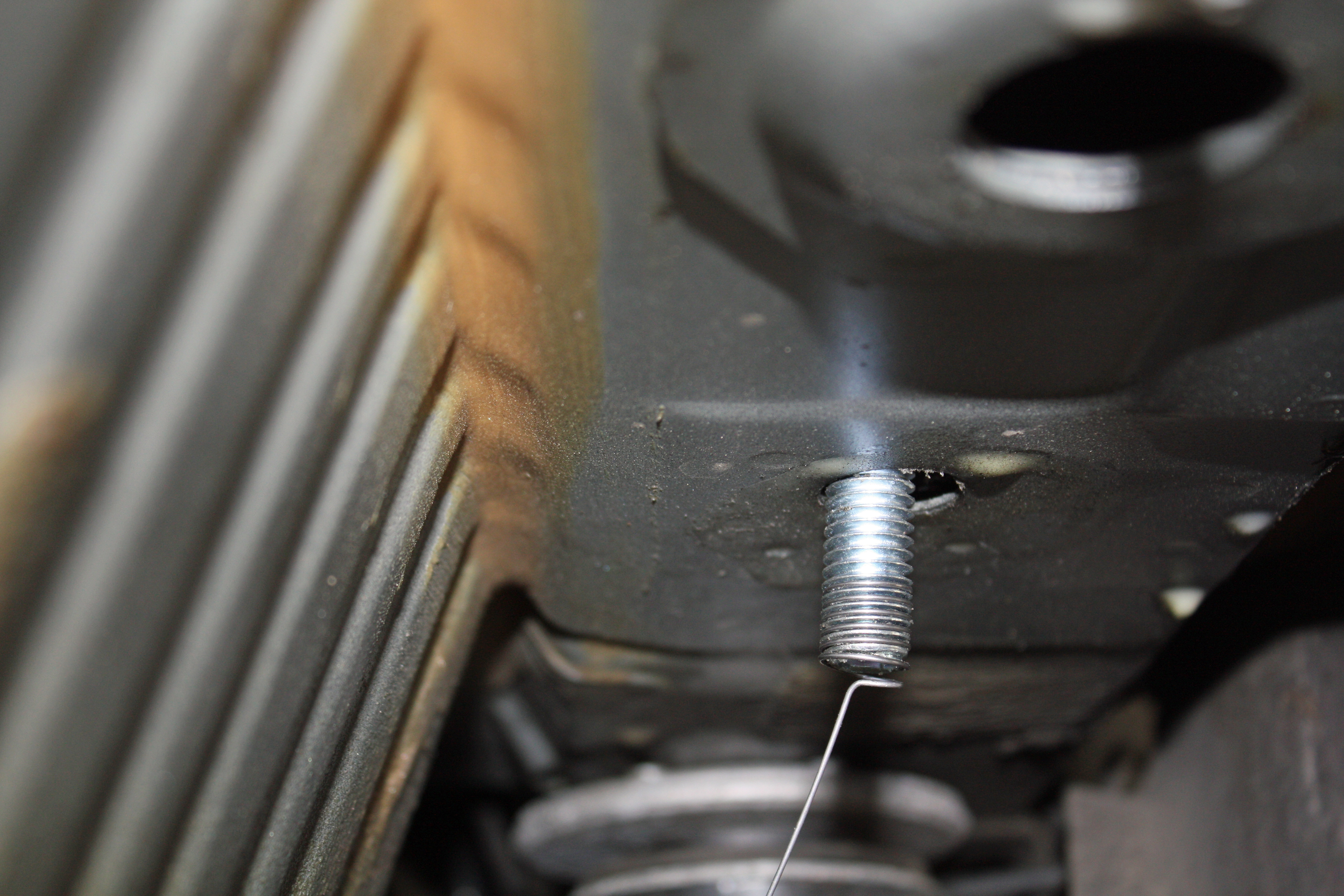
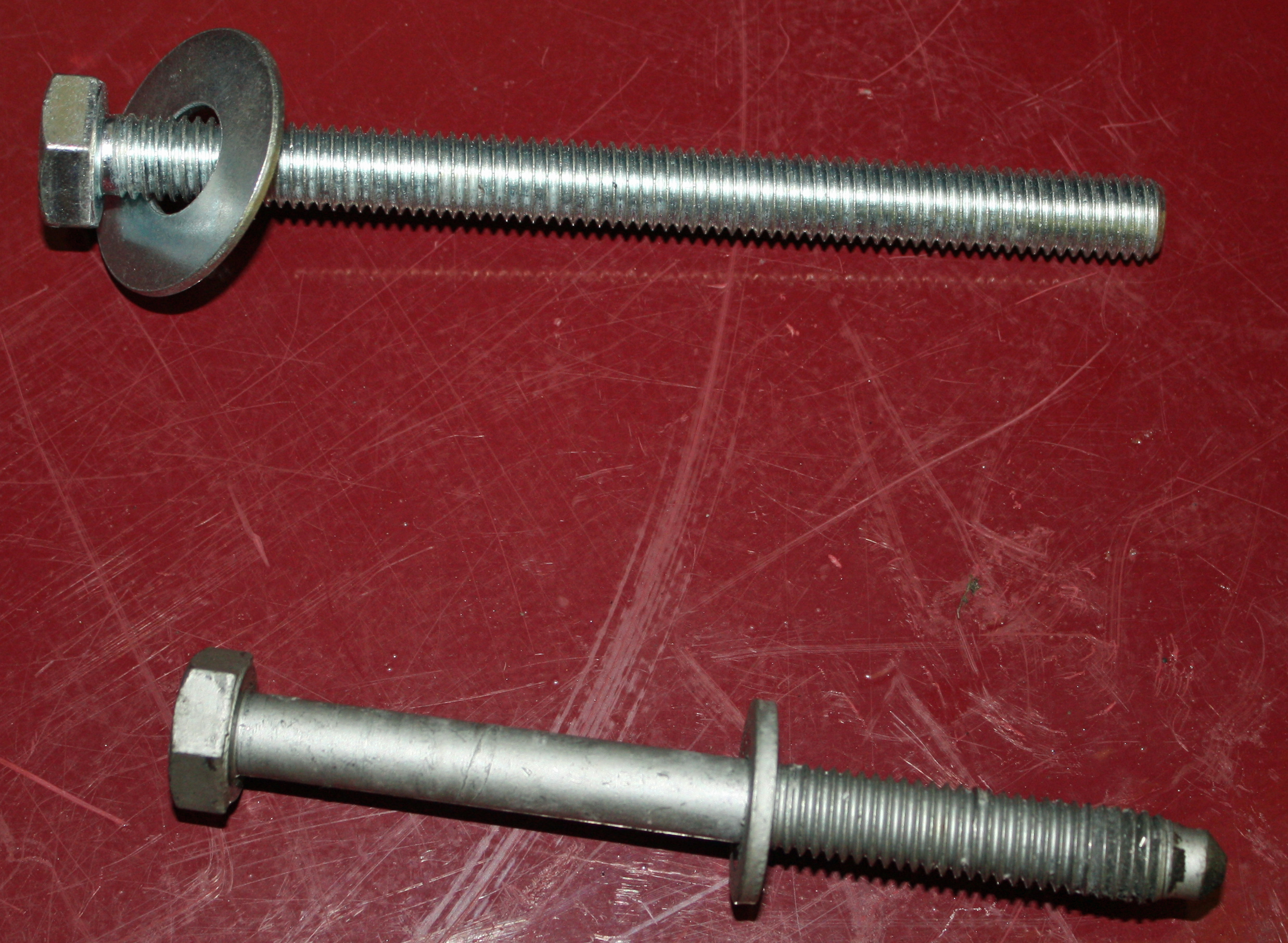
Nearly every hitch I have installed uses a bolt fisher.
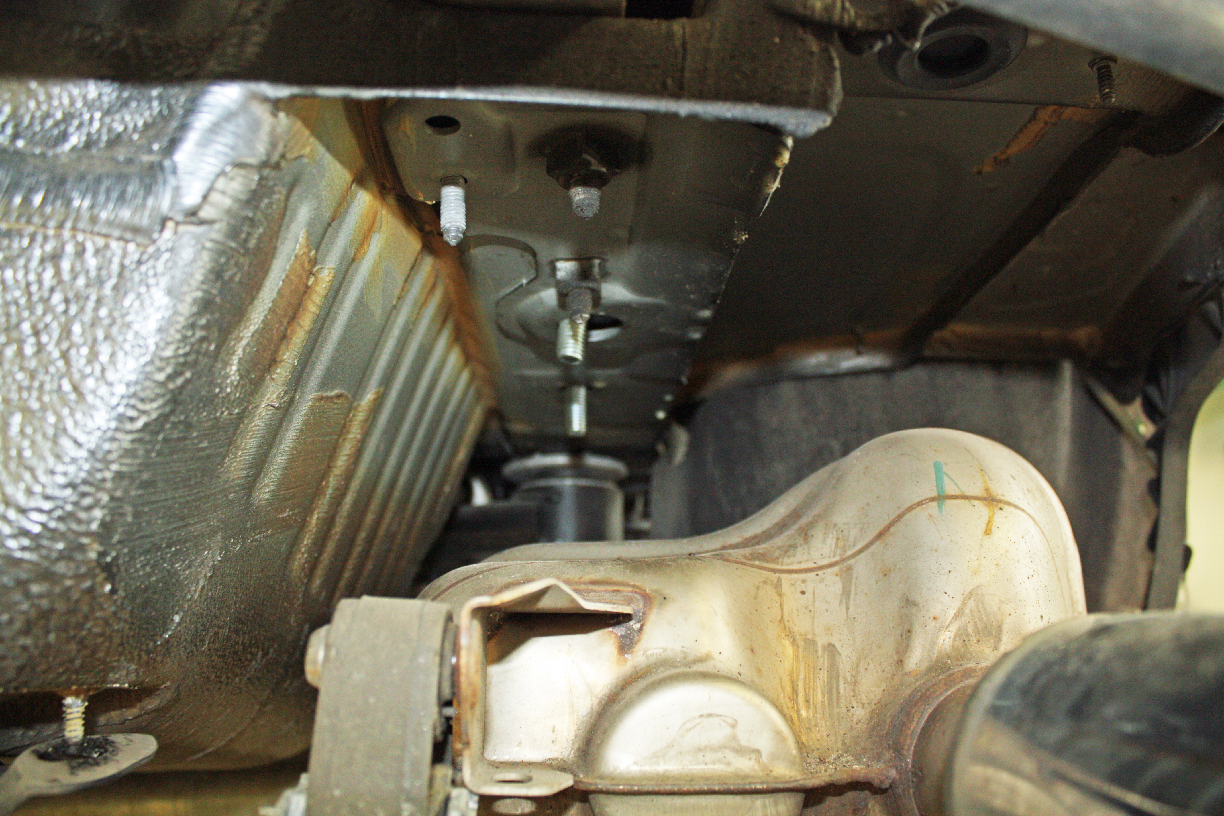
A bolt fisher works by screwing the end of the bolt fisher to a carriage bolt that has been placed through a plate washer of some kind with a square hole for the carriage bolt. The bolt and the fisher are fed into a hole and then pulled through another hole with the bolt now placed with the washer in position. In this case, feed the coil end through the forward most hole in the frame rail above the muffler and pull it out of the middle hole. The second bolt is then inserted into the middle hole and then pulled back out of the same hole. We now have two 1/2 inch bolts poking through the two front holes. Unscrew the bolt fish from the bolt once you have them in place and be careful not to push the bolt back into the hole.
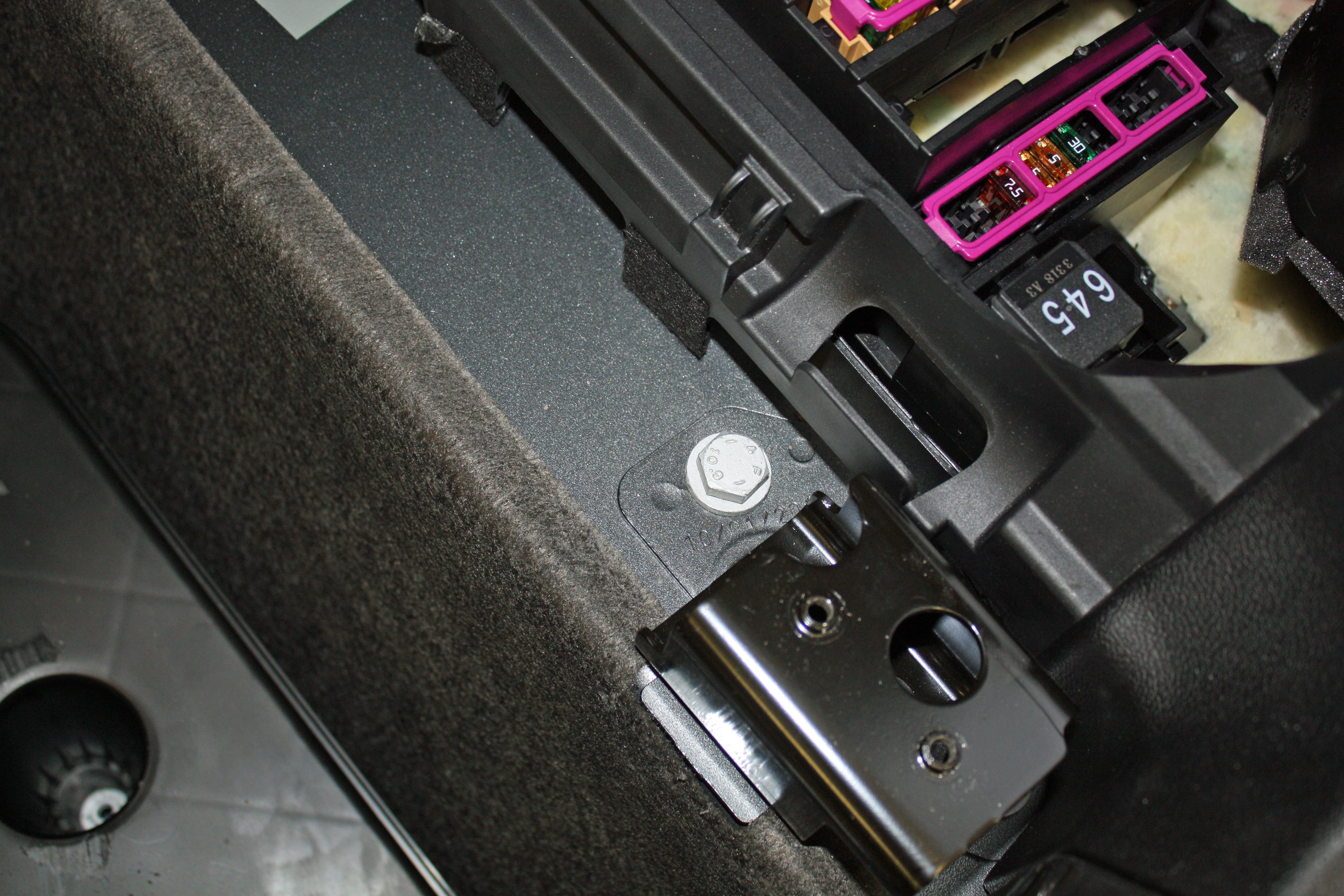
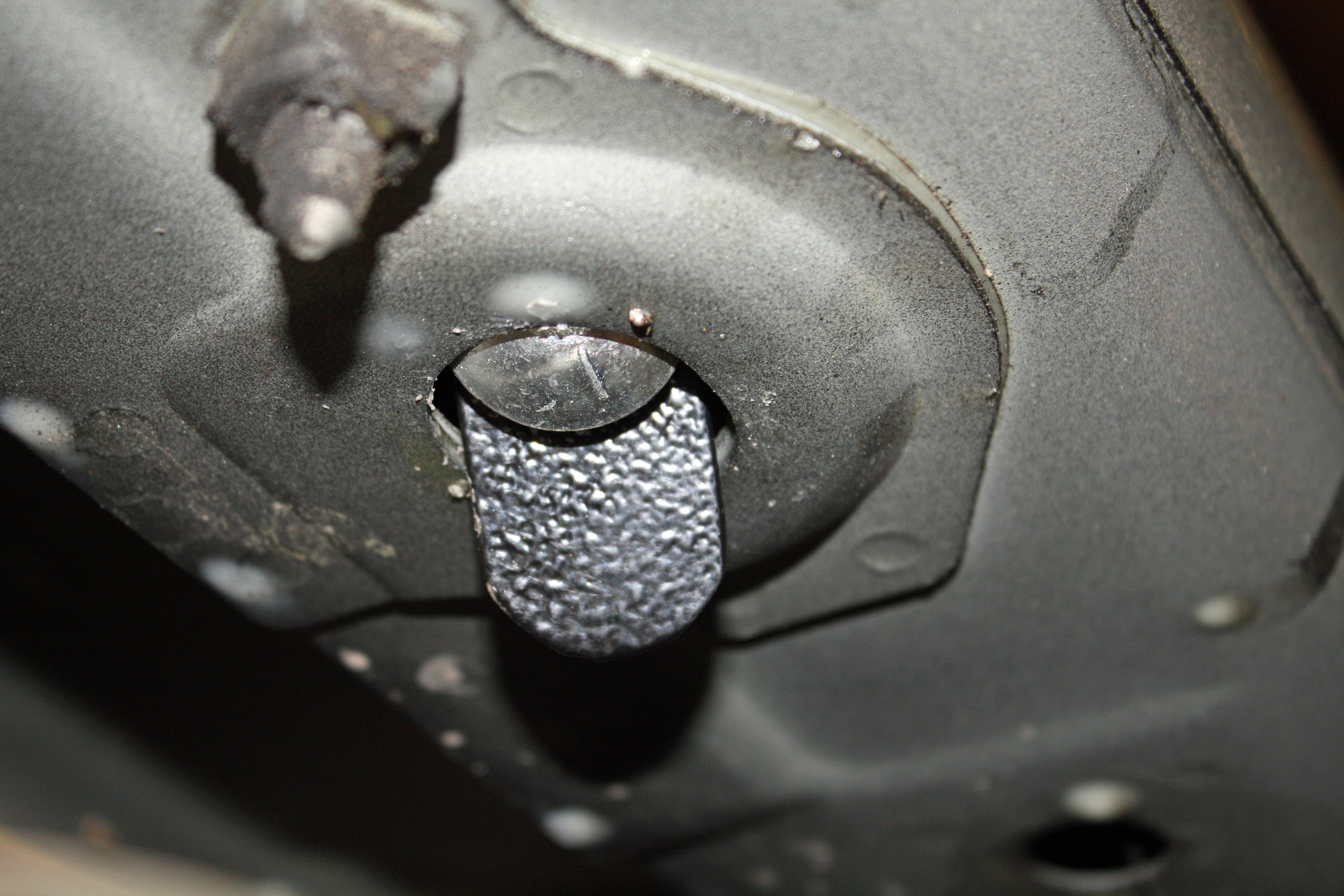
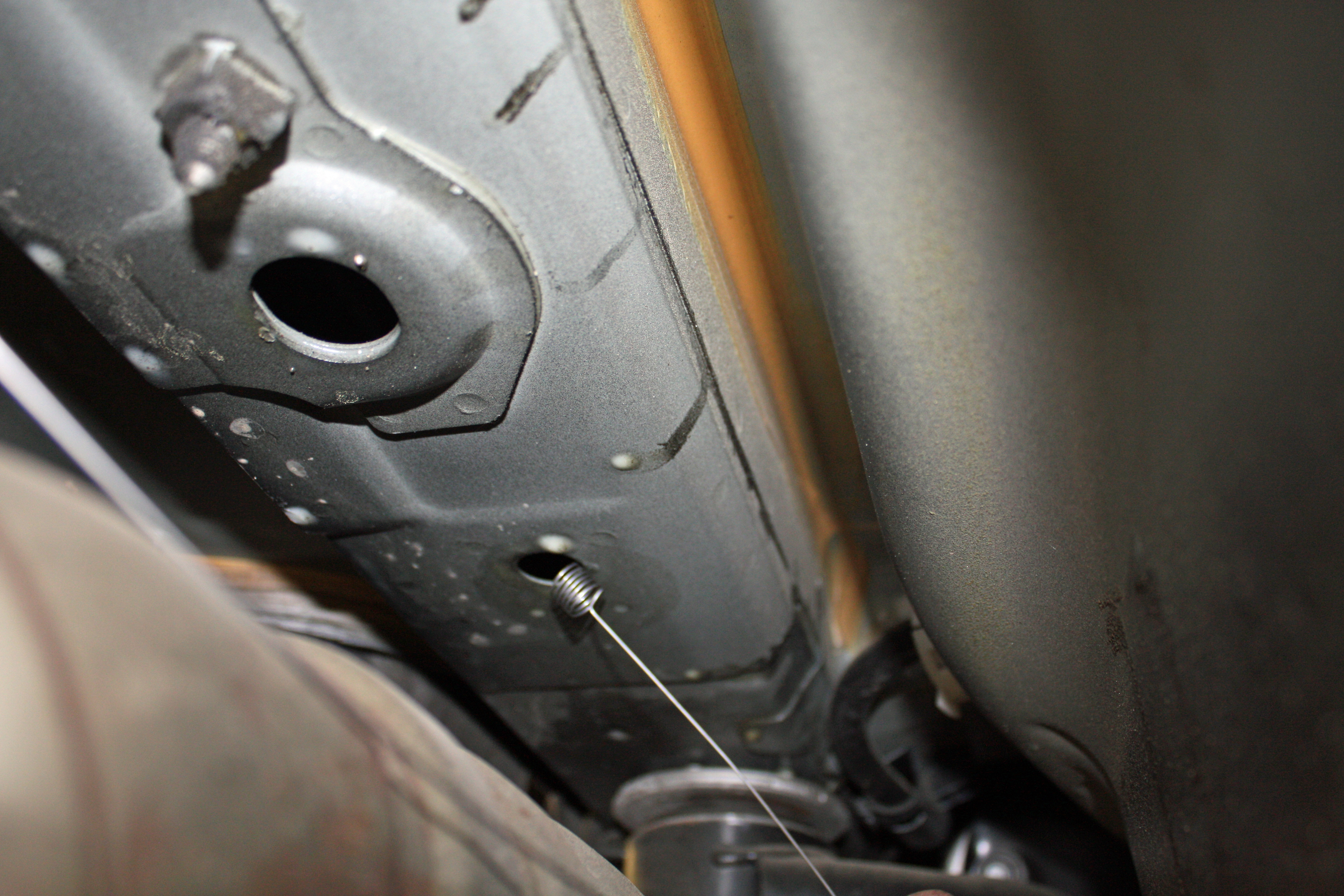
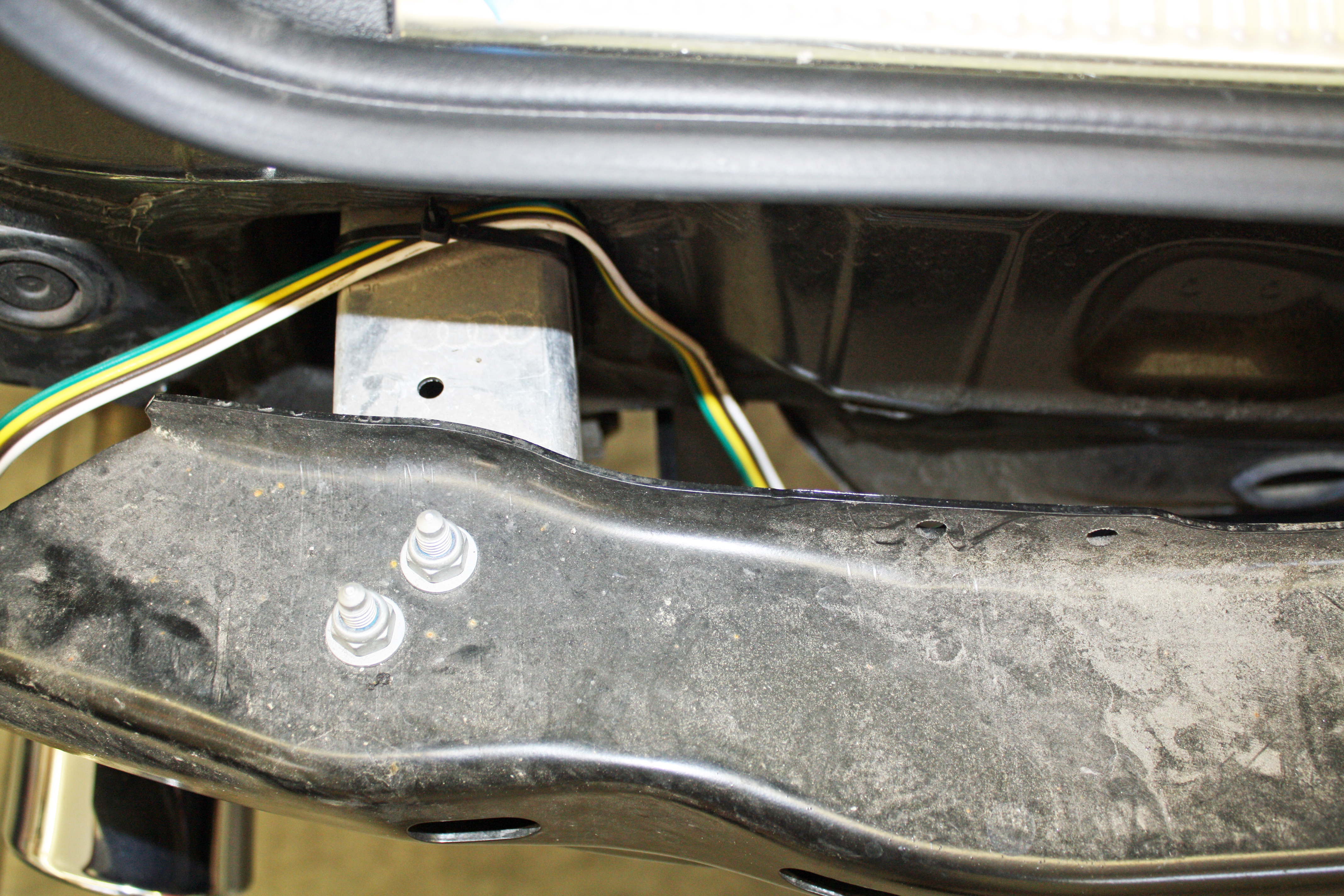
Now we remove the 10 mm bolt next to the tie-down that I mentioned earlier. It is replaced with a longer bolt that will extend down below the frame rail and will be come the third bolt for mounting the hitch. Torque these bolts to 45 ft lb.
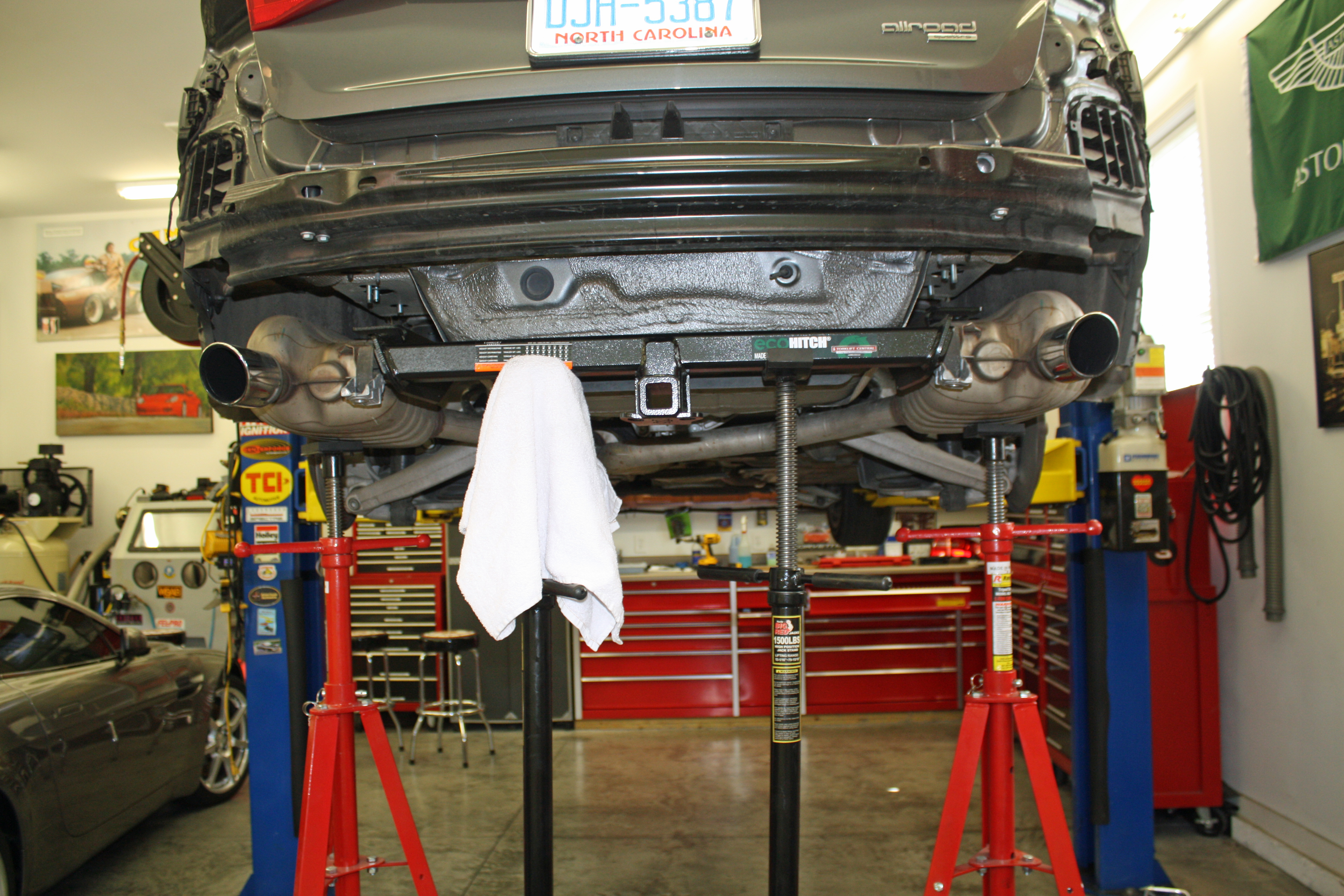
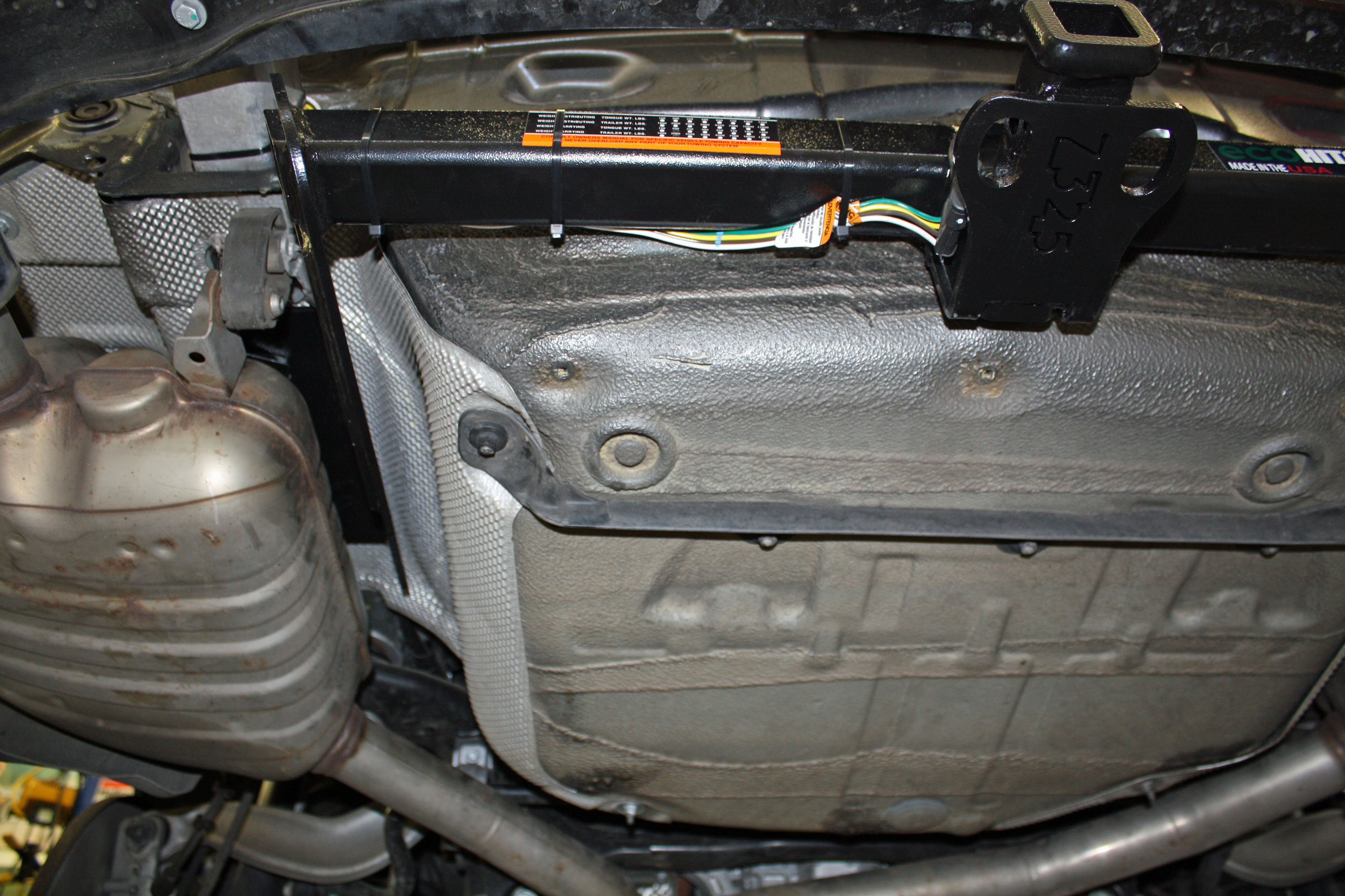
Re-install the heat shields. Raise the hitch into position while being careful to not push the mounting bolts back into the hole. Since I had the mufflers supported by stands, I used two more stands to support the rear of the hitch while I rested the sides on top of the mufflers. I gradually raised the rear of the hitch with the stands and then affixed the serrated flange nuts on the 1/2 inch mounting bolts. The M10 bolt is secured with a 2"x2" plate, a flat washer, a lock washer and the nut. The two half inch bolts are torqued to 75 ft lb while the M10 bolts is torqued to 45 ft lb. The muffler mounts can now be affixed.
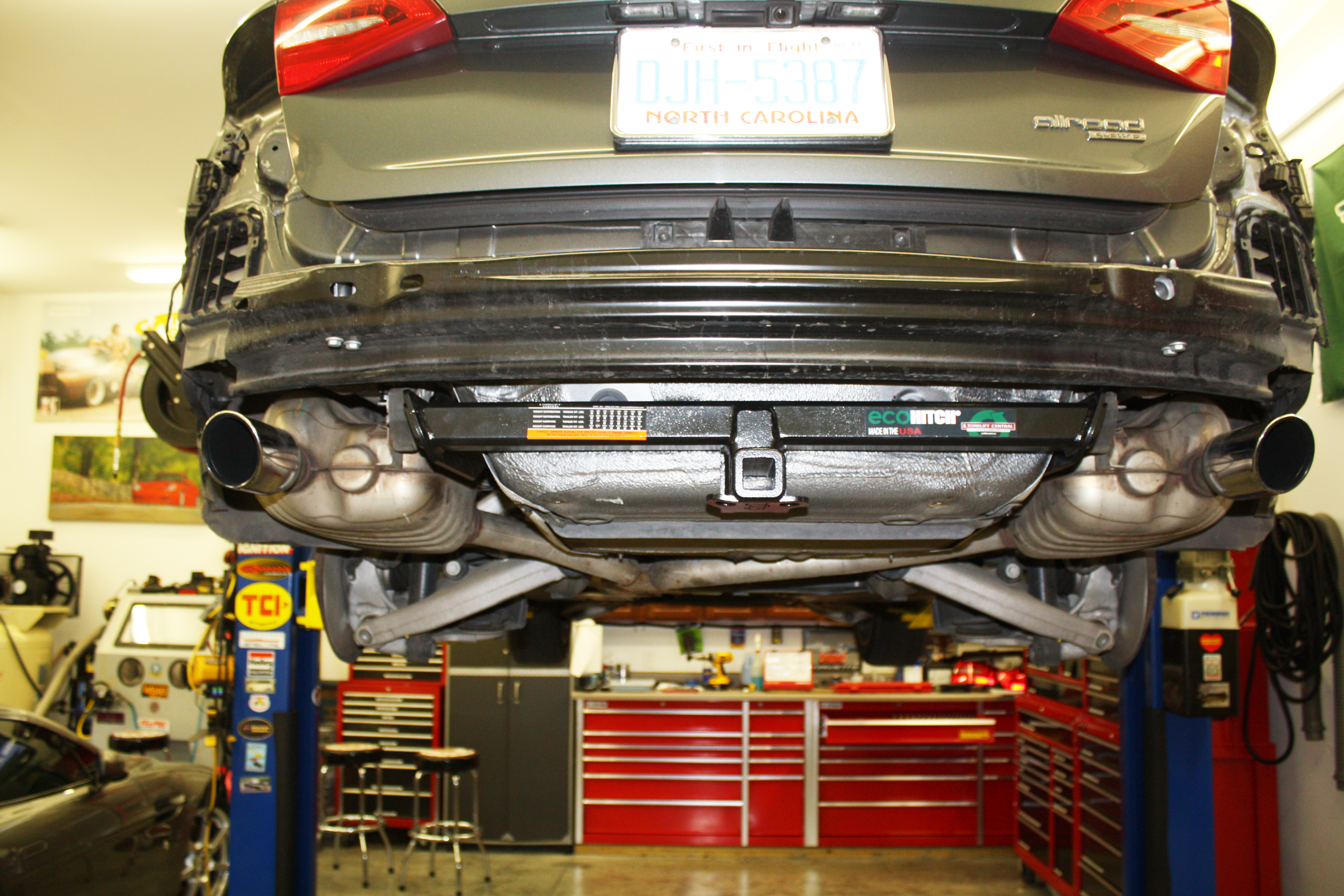
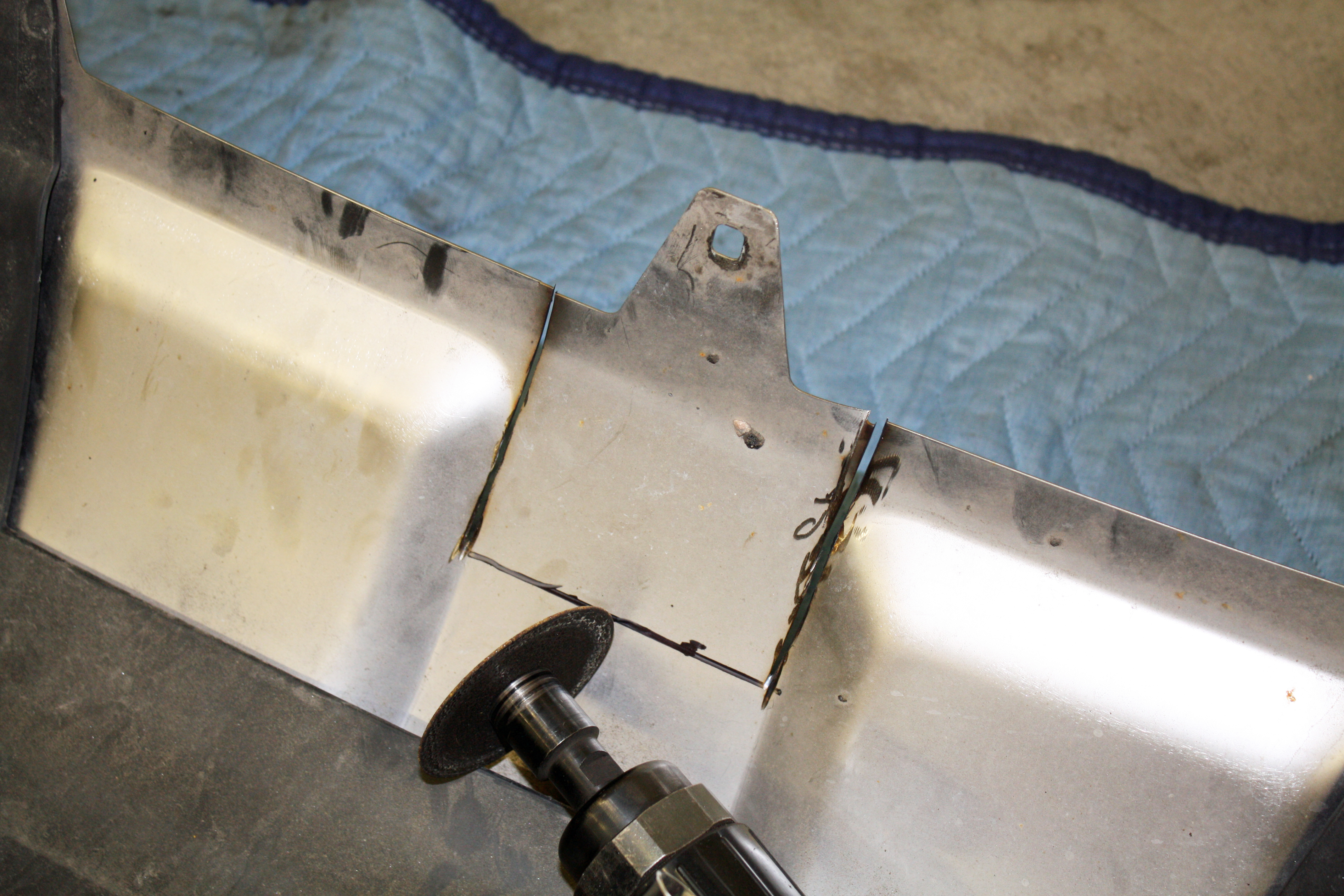
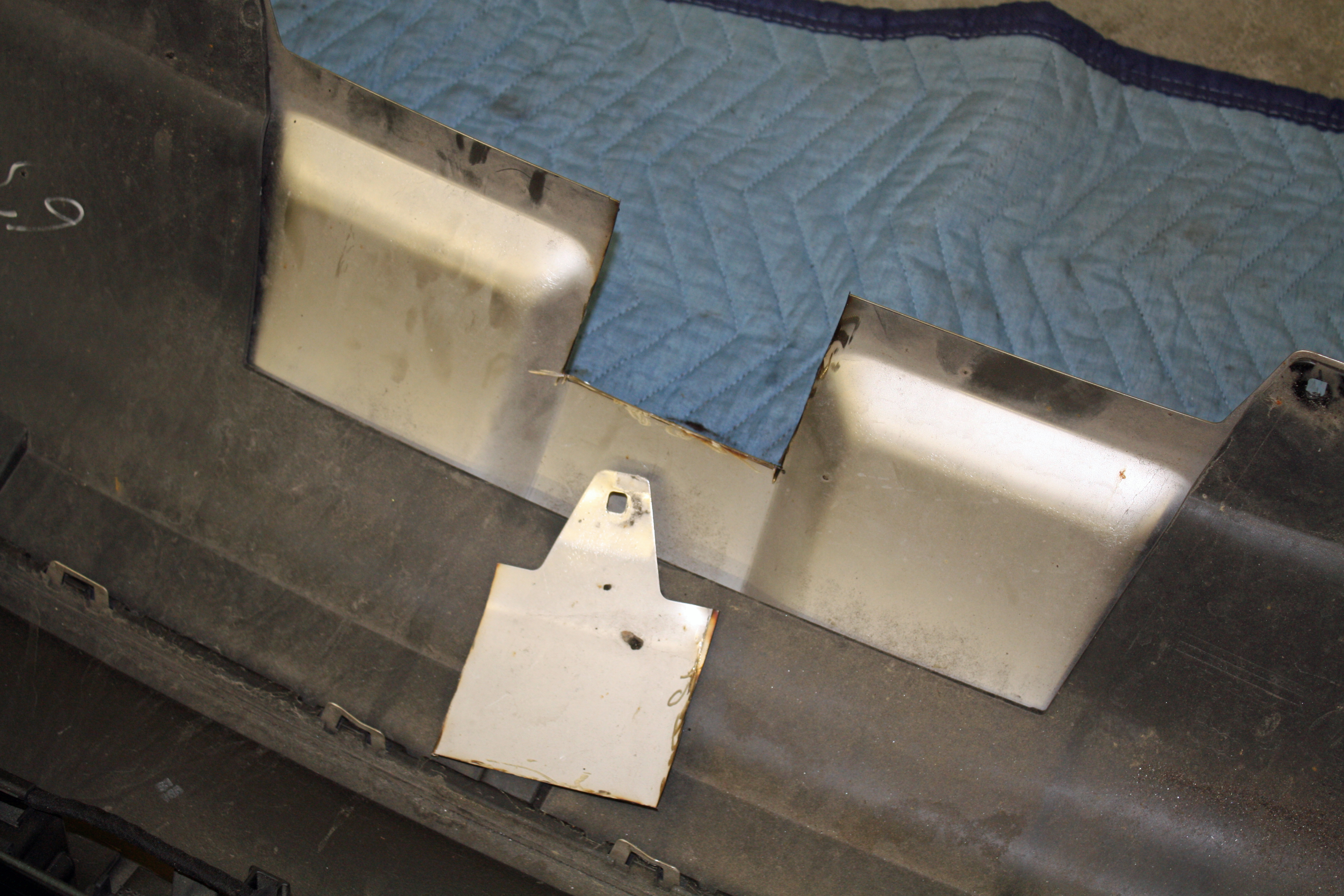
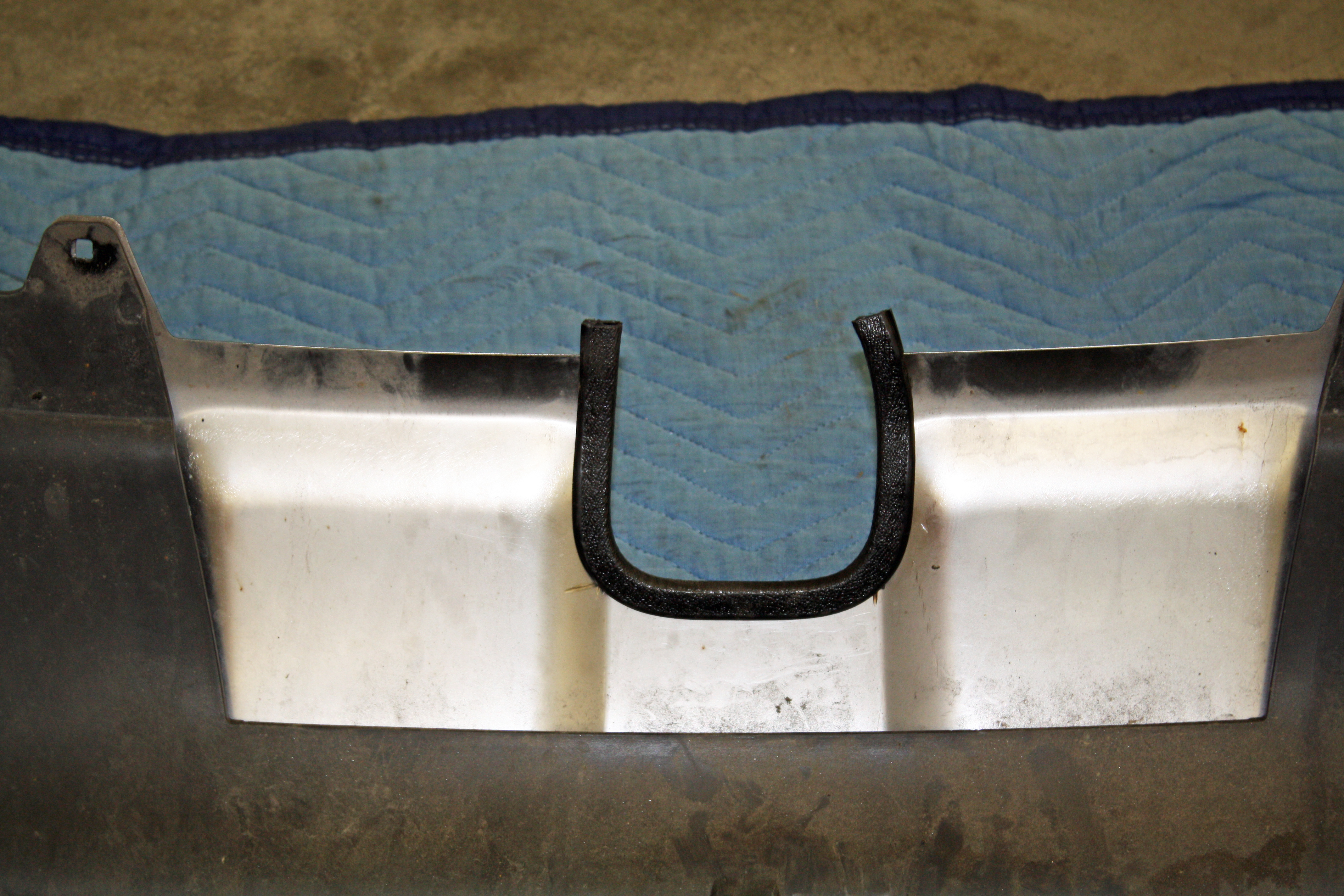
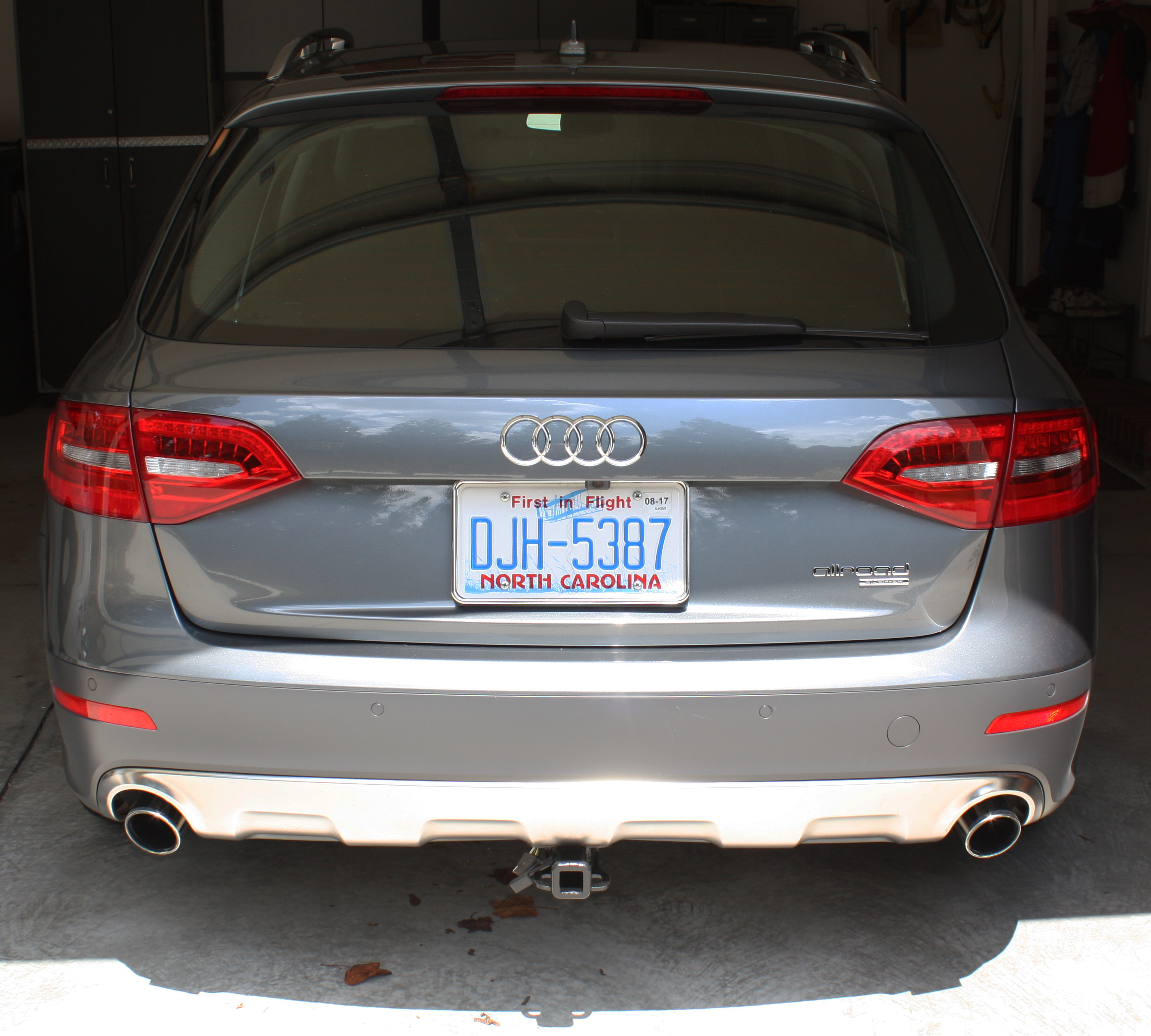
On the stainless steel part of the rear bumper cap, a center section must be removed for clearance for the hitch. Measure 5 1/4" from the tip of the center mount hole towards and then make the opening 4" wide. Since this is stainless steel, it is pretty tough. I used an air cut off saw to remove that section. Apply the included Trim-Lok around the opening. Once I had the bumper cap in place, I trimmed the excess from the Trim-Lok.
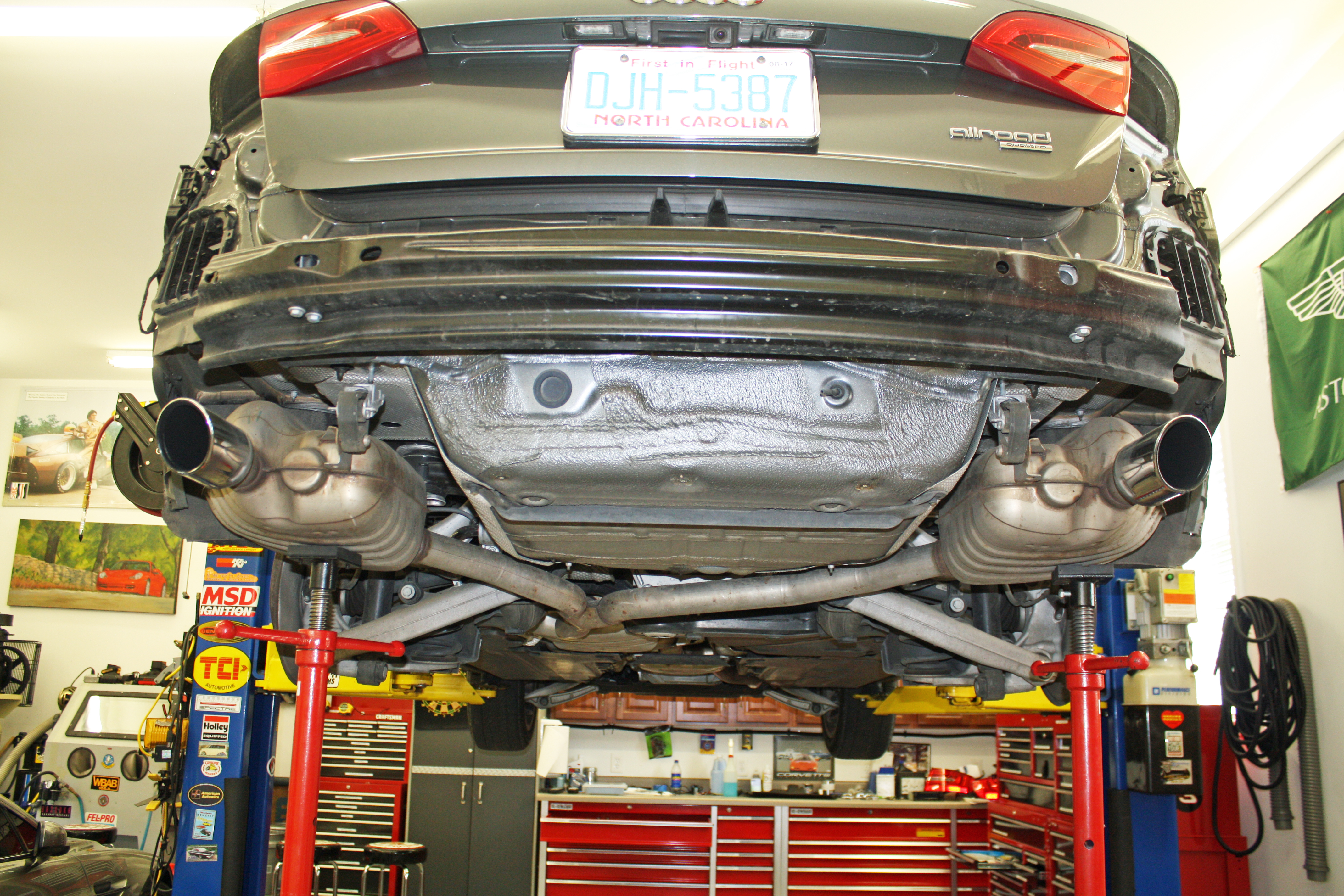
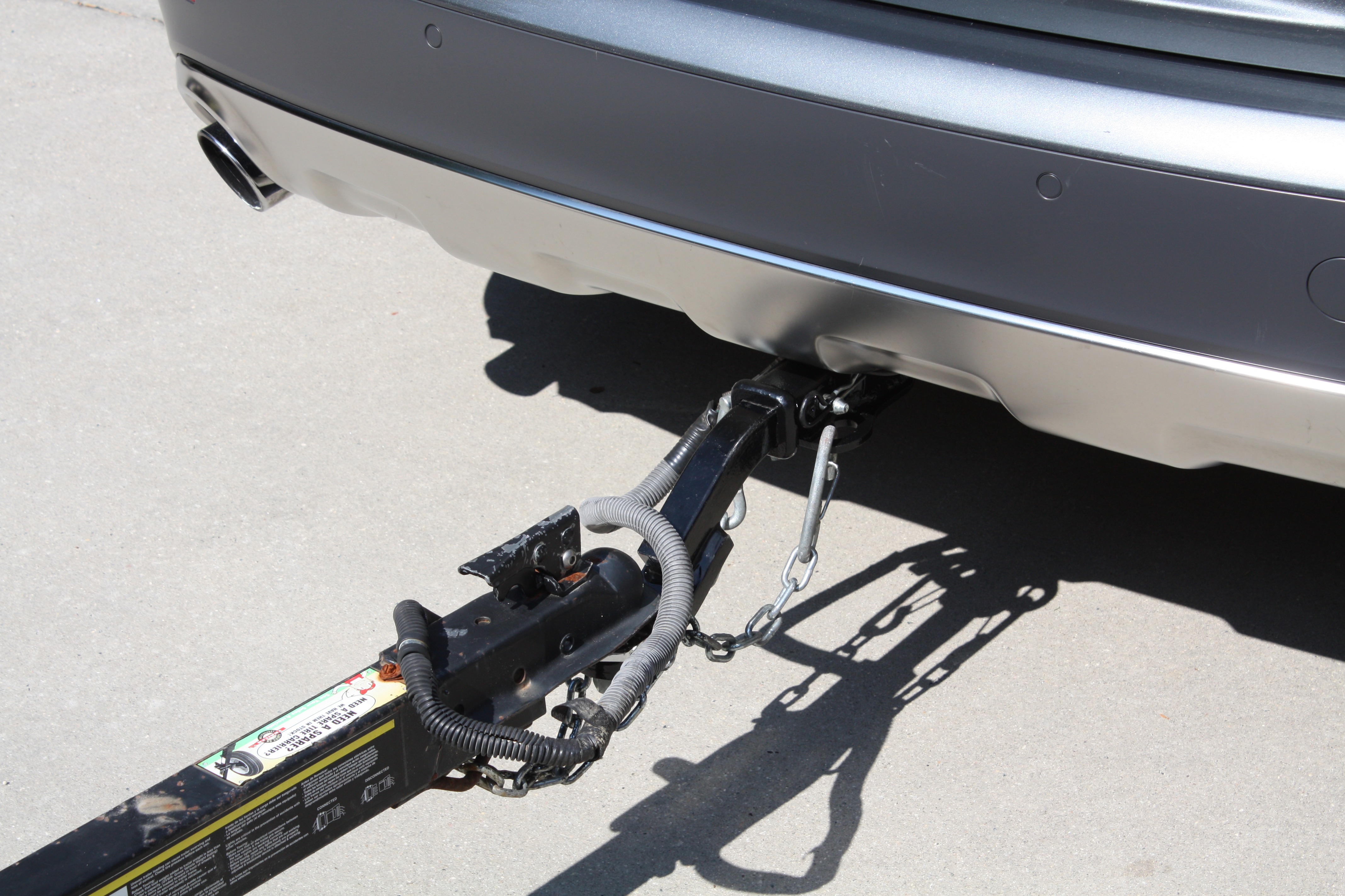
This is what it looks like when finished.
Now we move on to the wiring for the trailer. Unlike another thread here, my wiring solution works flawlessly with no codes.
Time for me to go to bed now so you all will have to wait until tomorrow for the exciting conclusion.
I bought the wiring kit on etrailer. There were two options for my 2014 Allroad. One was a conventional wiring kit which would involve soldering or otherwise connecting wires into the existing system.
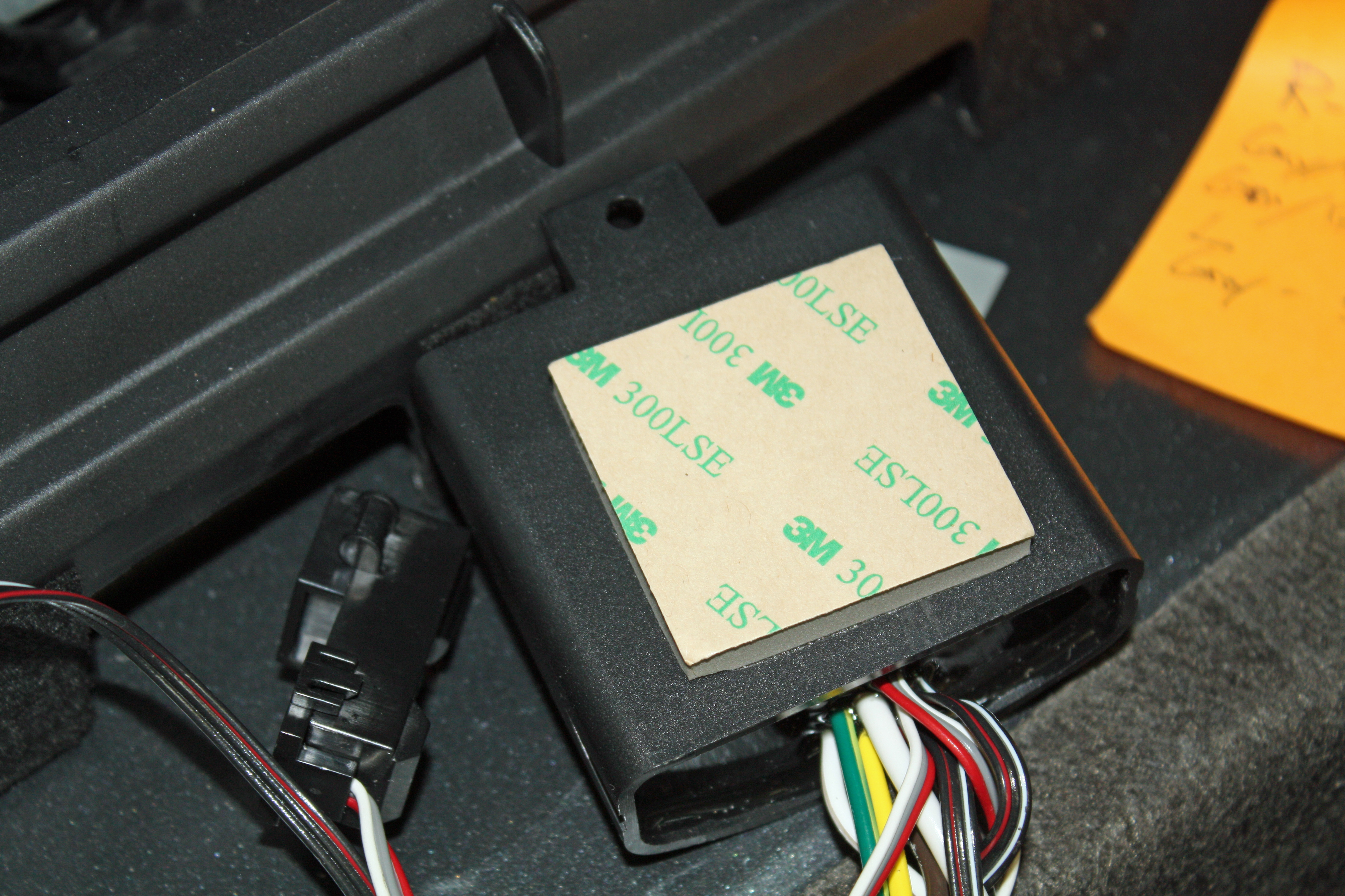
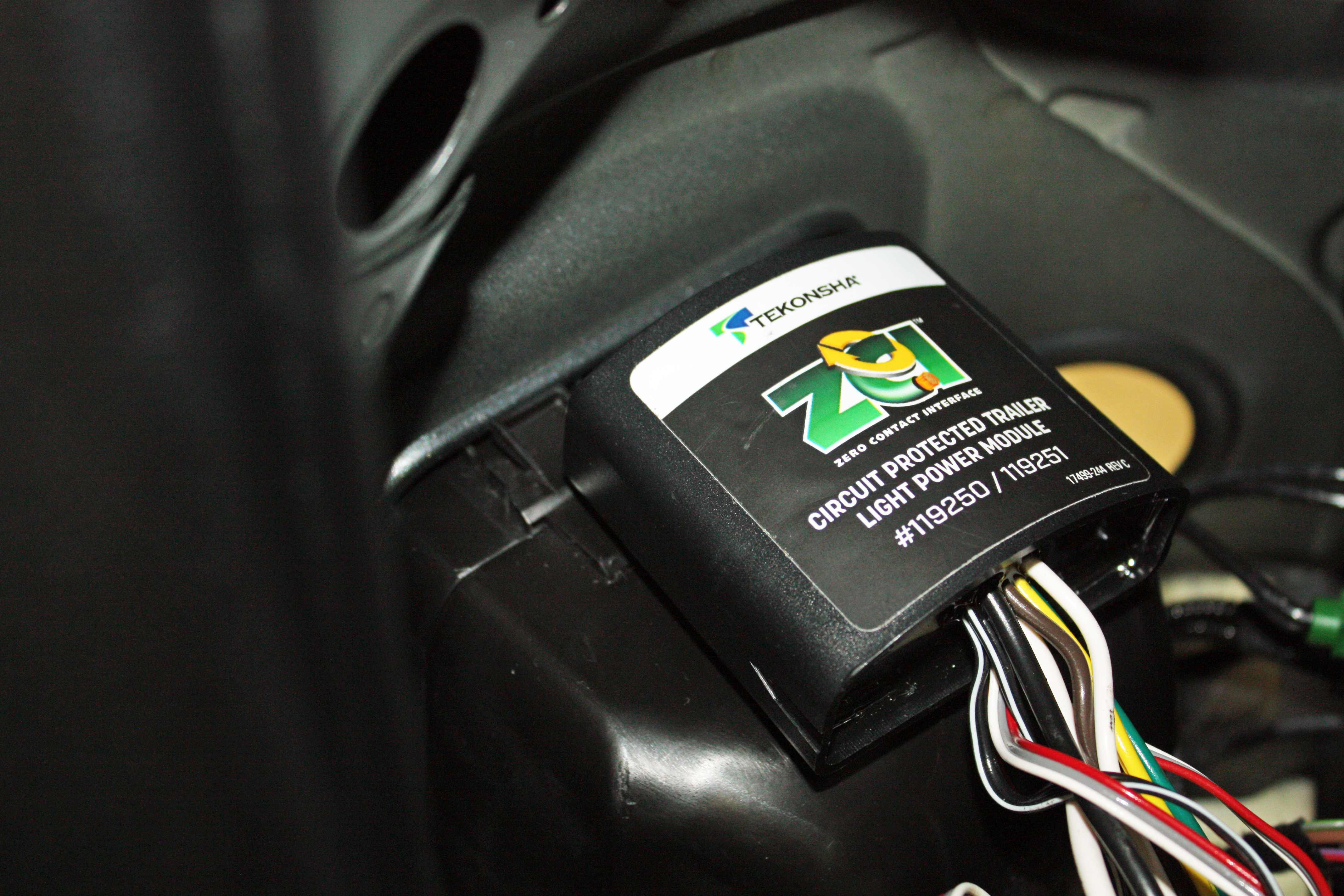
The other option was the ZCI Circuit Protected Vehicle Wiring Harness w/ 4-Pole Flat Trailer Connector and Installation Kit. No wiring splices are required with this kit. The wire with the desired signal is placed into the connector which uses induction to read the signal. Again, this kit was more expensive then the traditional kit but it promised to work well with today's electronics.
As I usually do, I broke out my voltmeter to deduce which wires had the voltage I was looking for. I turned on the left turn signal, went to the left rear turn signal connector, and found that I was getting an alternating 12V signal on both the Grn/Blk and Gray/Blk wires and was also getting a 5.5V signal on the solid gray wire. So three out of the five wires had voltage to them.
The right turn signal showed Grn/Blk and Gray/White wires with the alternating 12V signal and the 5.5V on the solid gray wire.
Applying the brakes gave the same voltages on both sides as listed above.
Turning on the running lights resulted in a 12V signal on the solid gray wires on both side with the Gray/Blk and Gray/White wires showing 5.5V on both sides.
I could see now that clearly the solid gray wire was the running light source, but I was confused about which wire to select for the turn signals and brake lights. So I called Tekonsha. The gentleman there was very helpful. Basically what their system is looking for is a change in amperage. It was obvious that the brakes and turn signals were all being controlled together. He didn't think it mattered which of the Grn/Blk, Gray/Blk or Gray/White wires I chose.
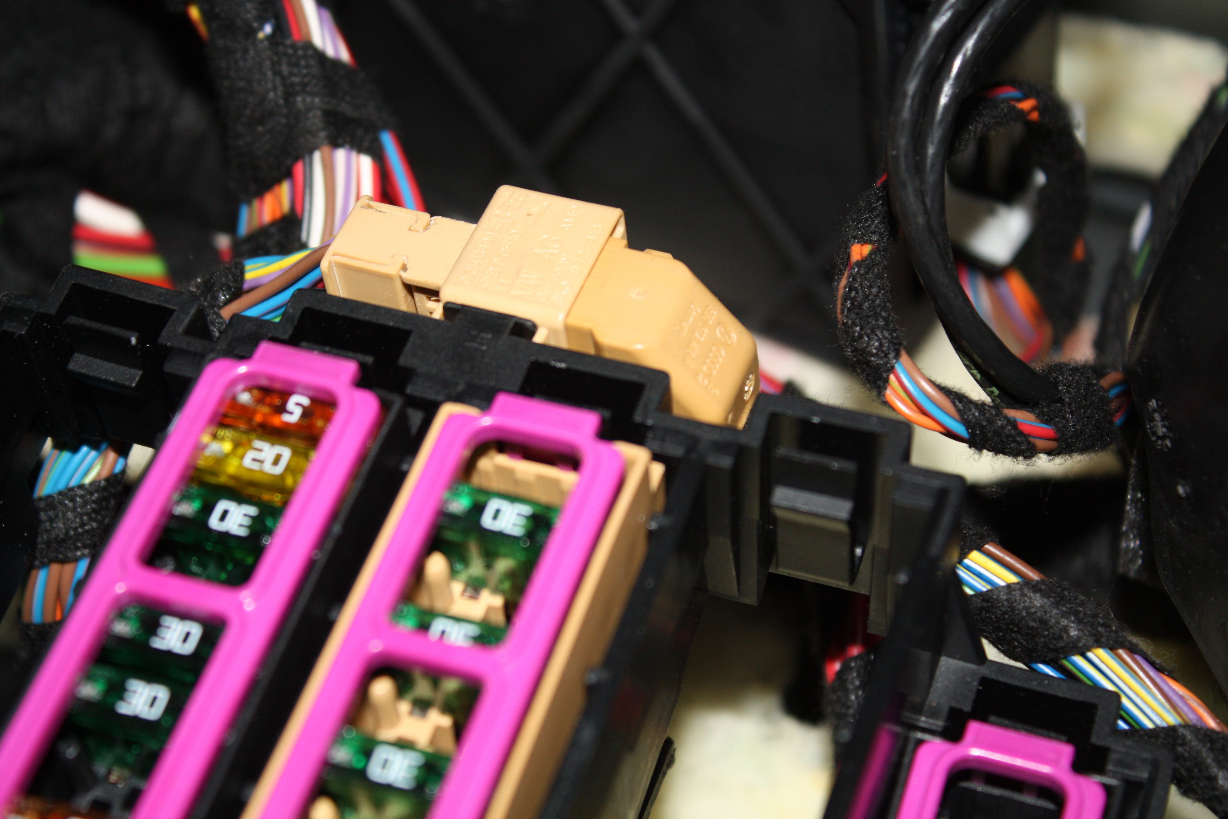
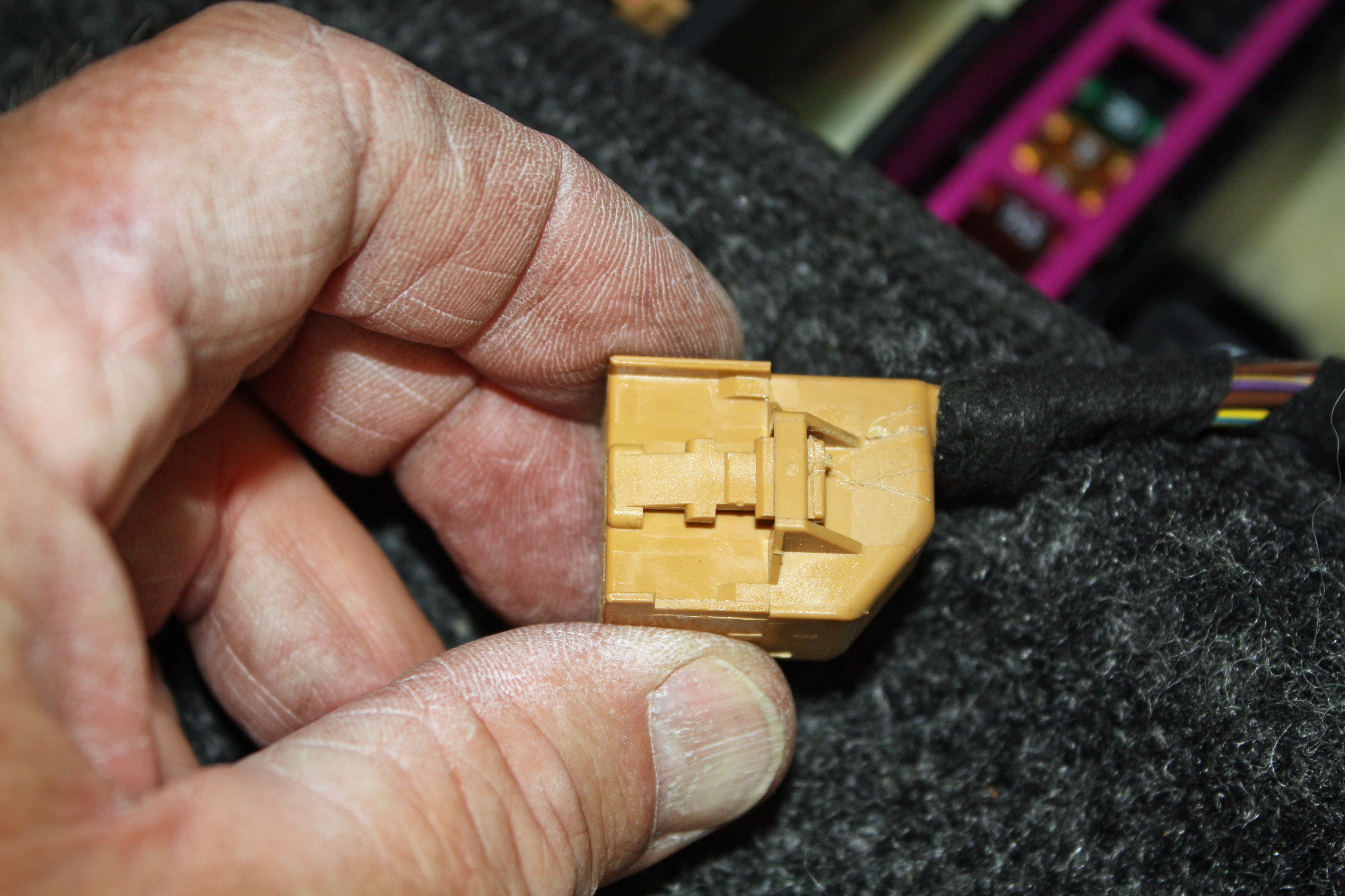
The way their system works is, once you place the appropriate wires in their connectors, you must place the control module in the "learn" mode. You do this by removing the 15Amp fuse for the module, start the engine, and make sure all of the lights are off.
You then insert the fuse which initiates the "learn" mode in the module. Now one simply turns on the running lights for five seconds, then each of the turn signals for five seconds and apply the brakes for five seconds. The module calculates the amperage used for each function and sends the appropriate signal to the trailer wiring harness. It worked like a charm. The trailer lights were bright and there were no fault codes showing on the dash.
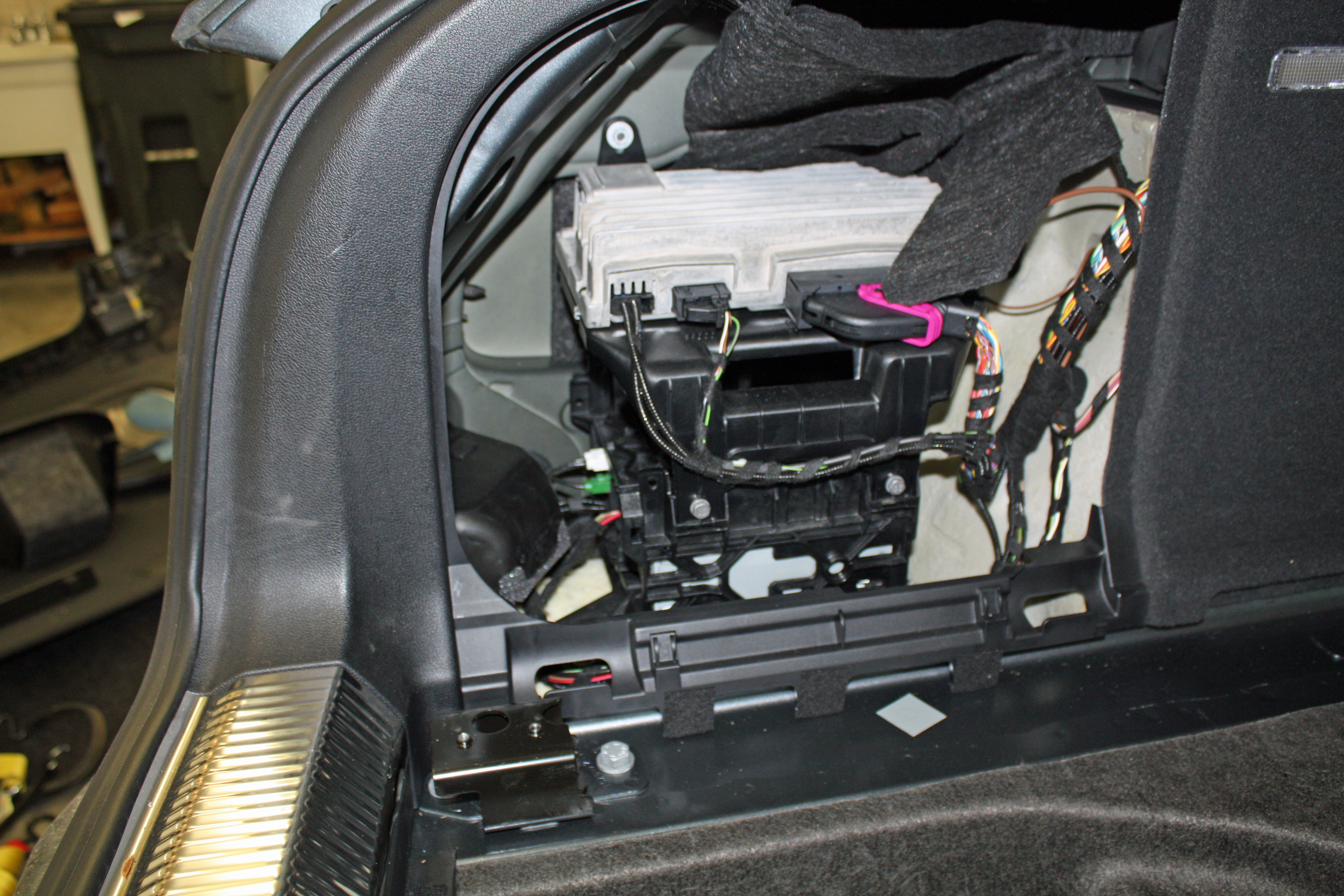
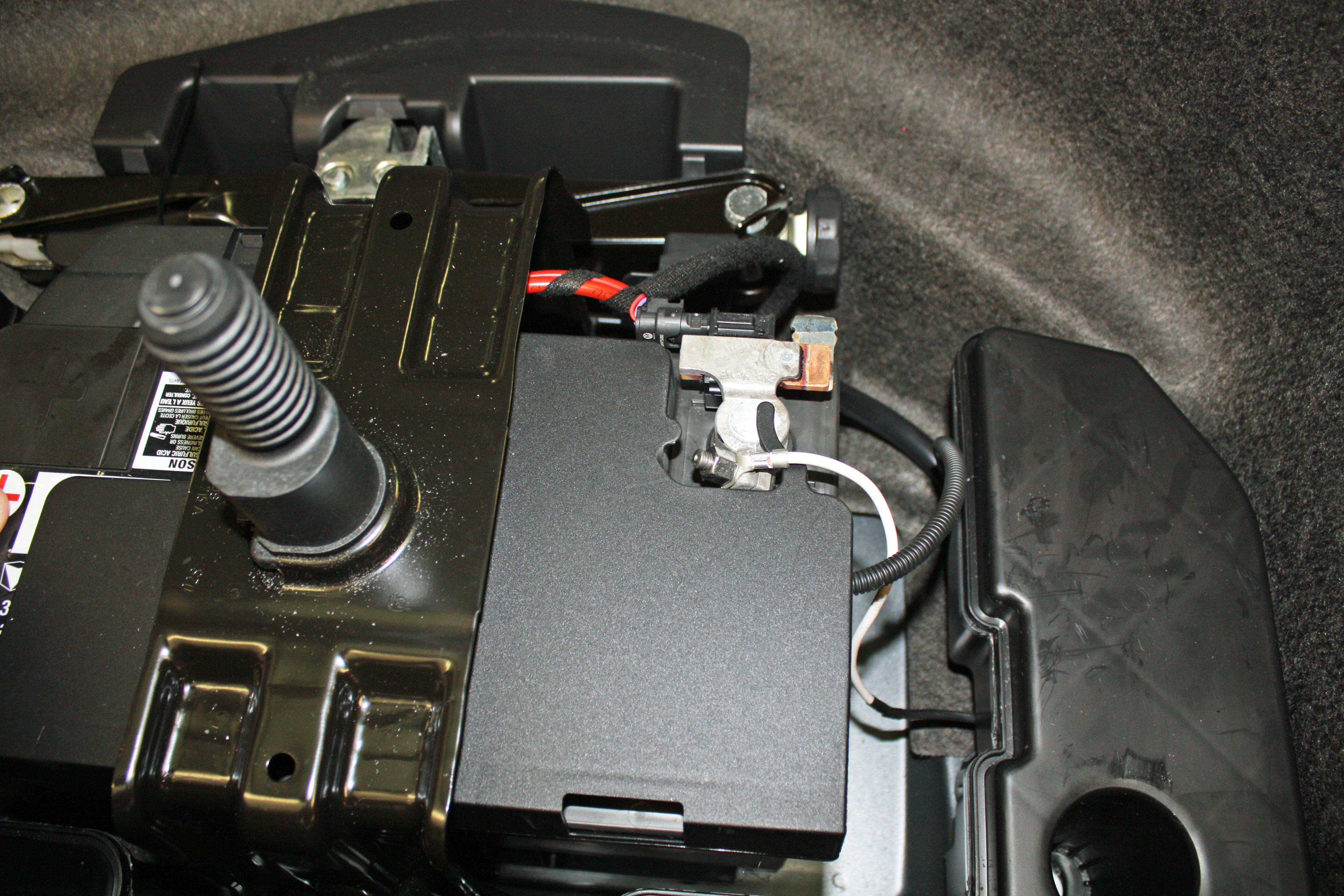
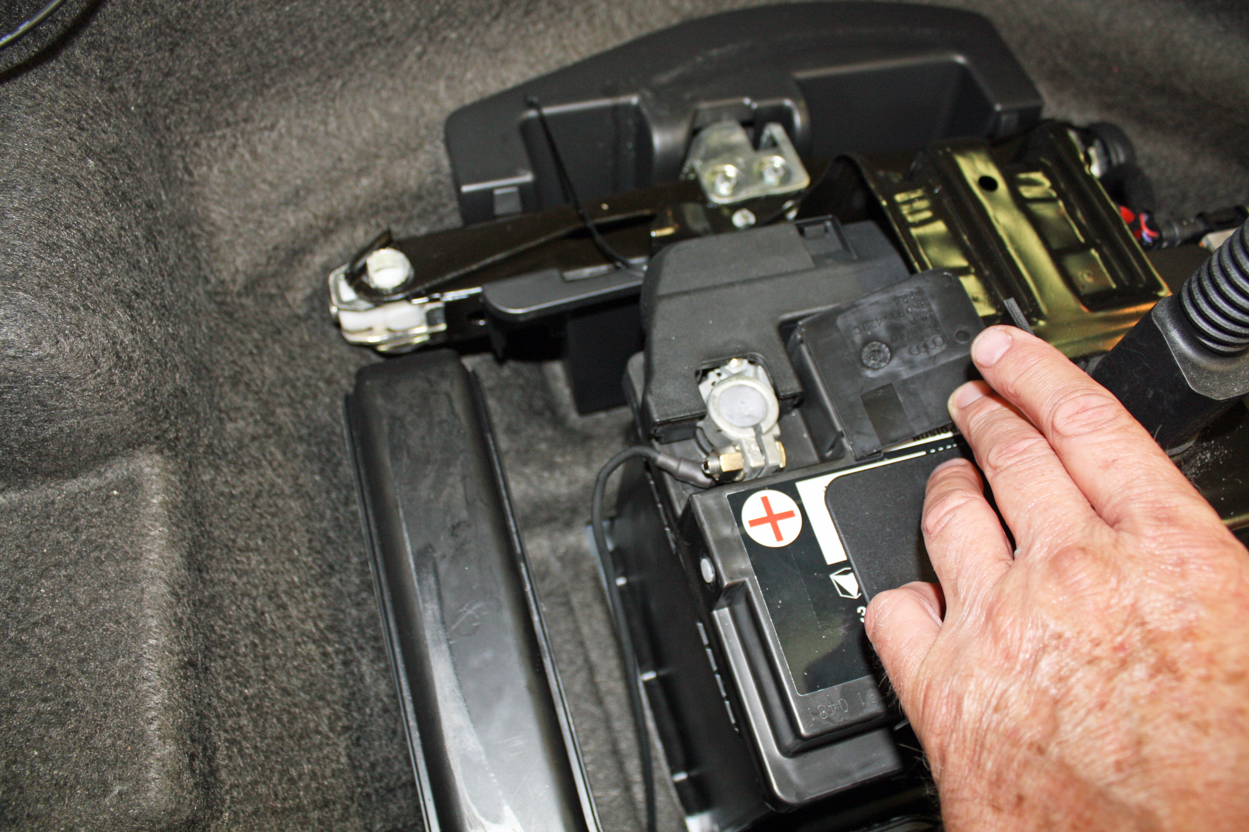
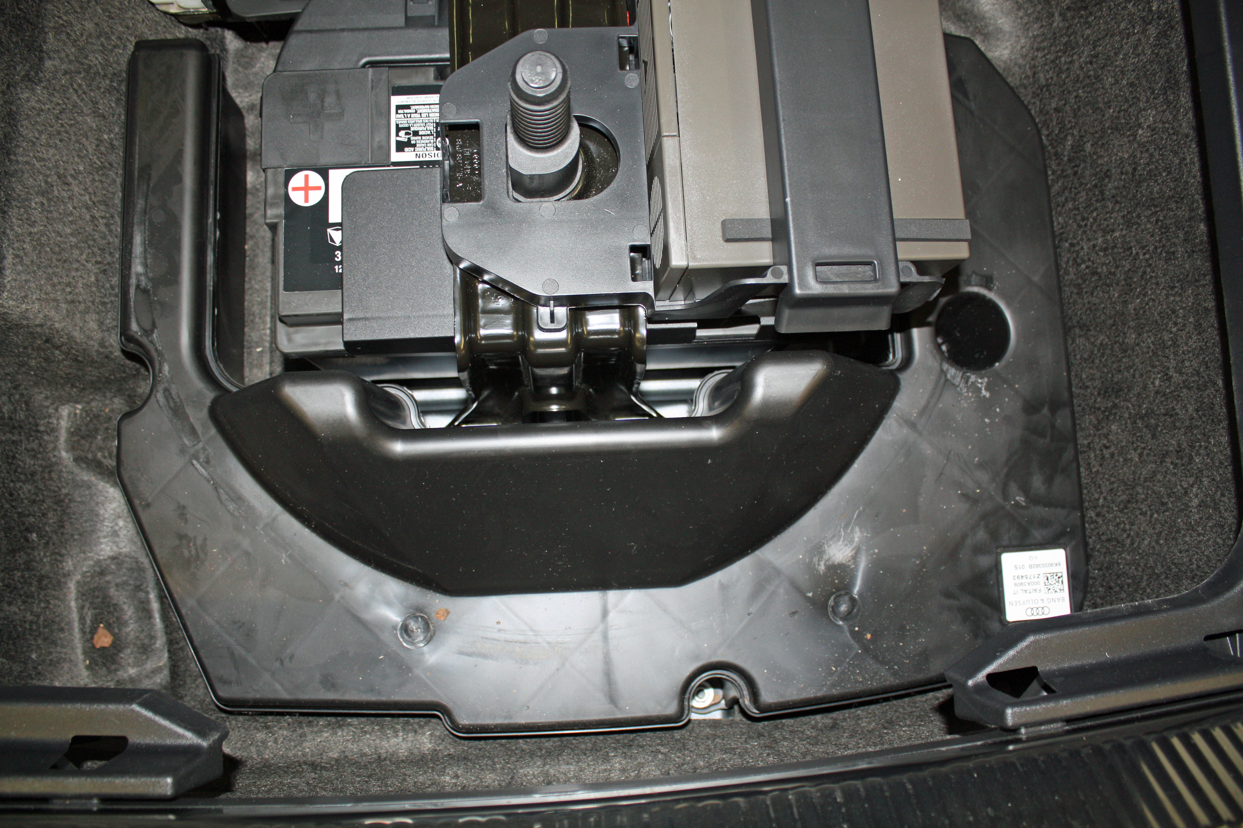
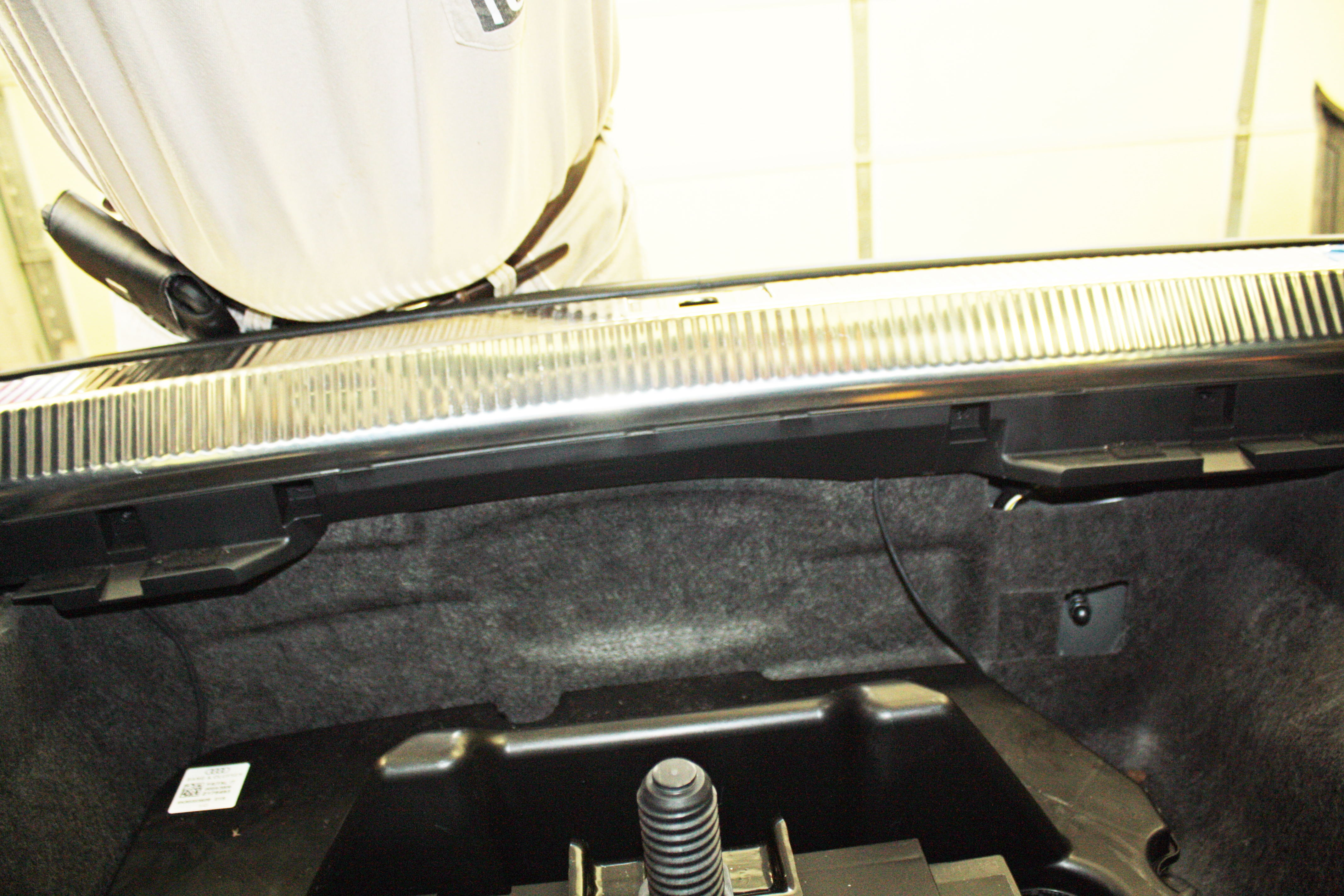
The module must be wired to a 12V constant source. Luckily our Allroad's have the battery underneath the spare tire so it was a short run to the module. I decided to place the module behind the panel in the left rear corner. To get the 12V wire and the ground wire to that area, I loosened the three 10mm nuts on the speaker enclosure in the spare tire well. I then ran the wires under that speaker back to the rear and tucked them under the rear trim piece. The wires for hooking up the right rear lights also were tucked under this trim piece to run to the left side.
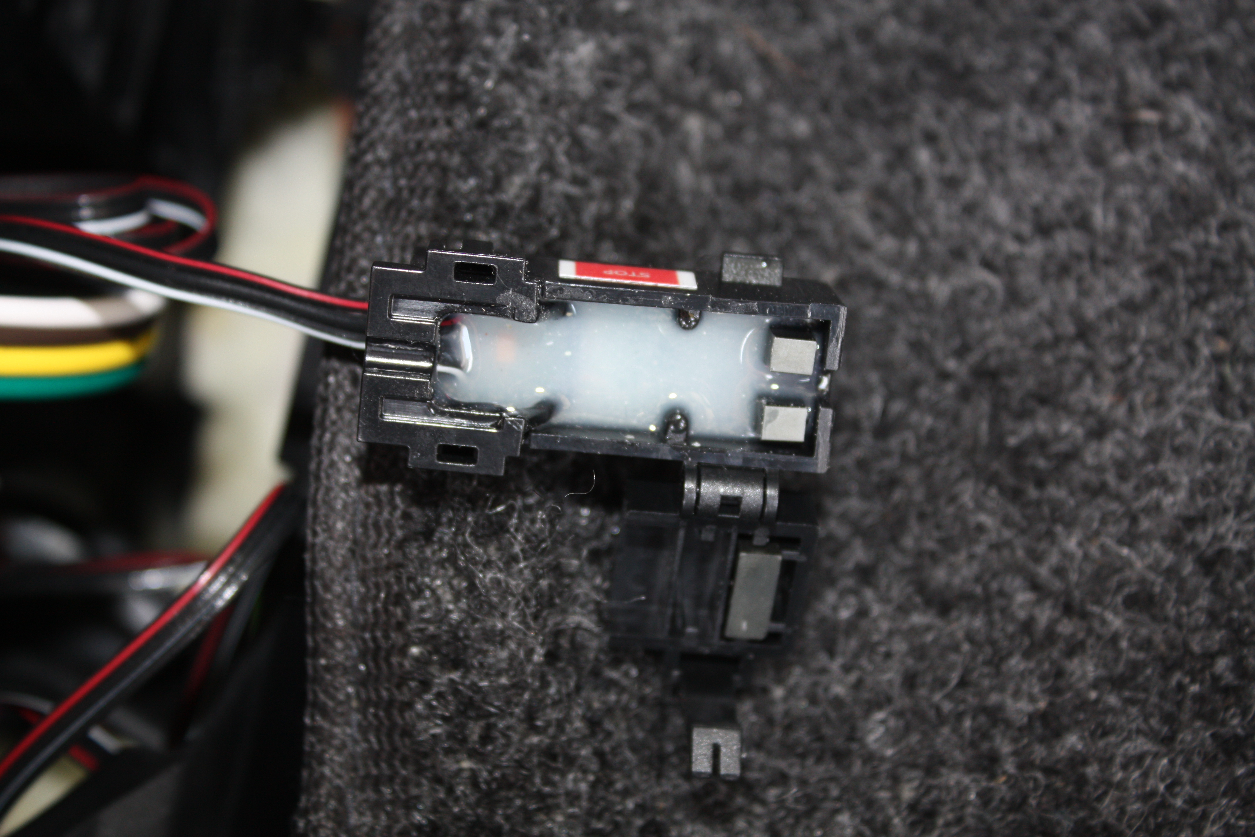
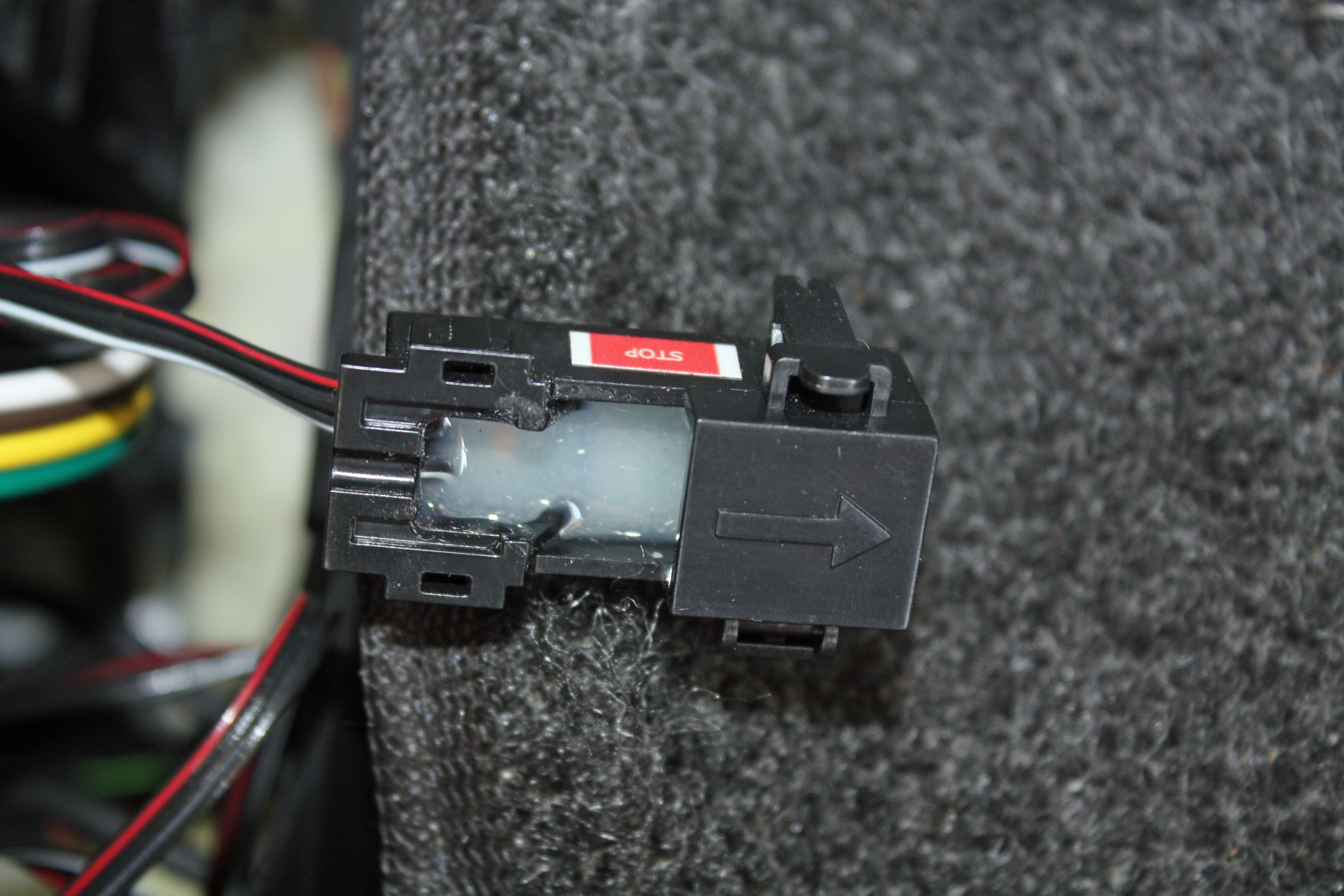
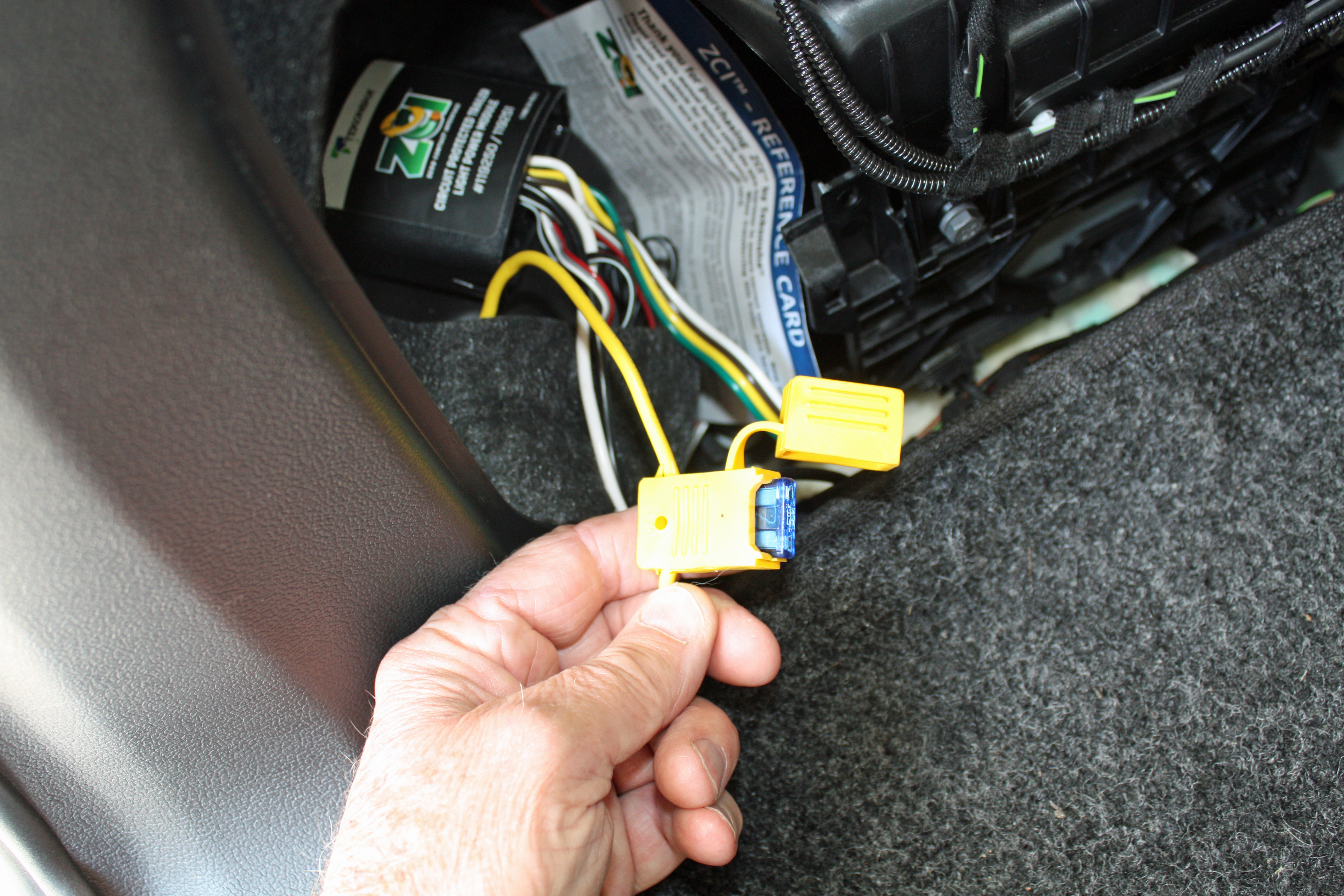
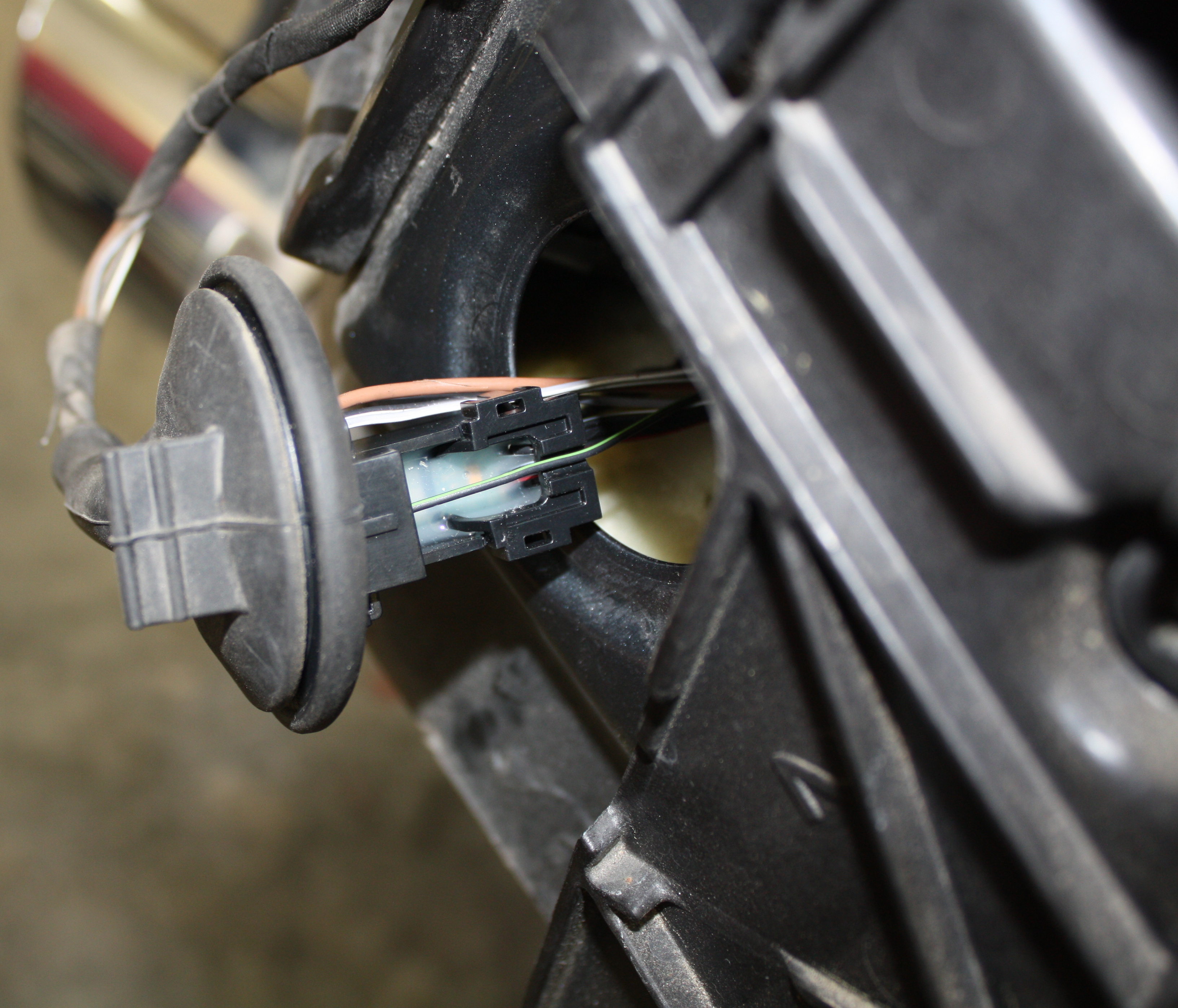
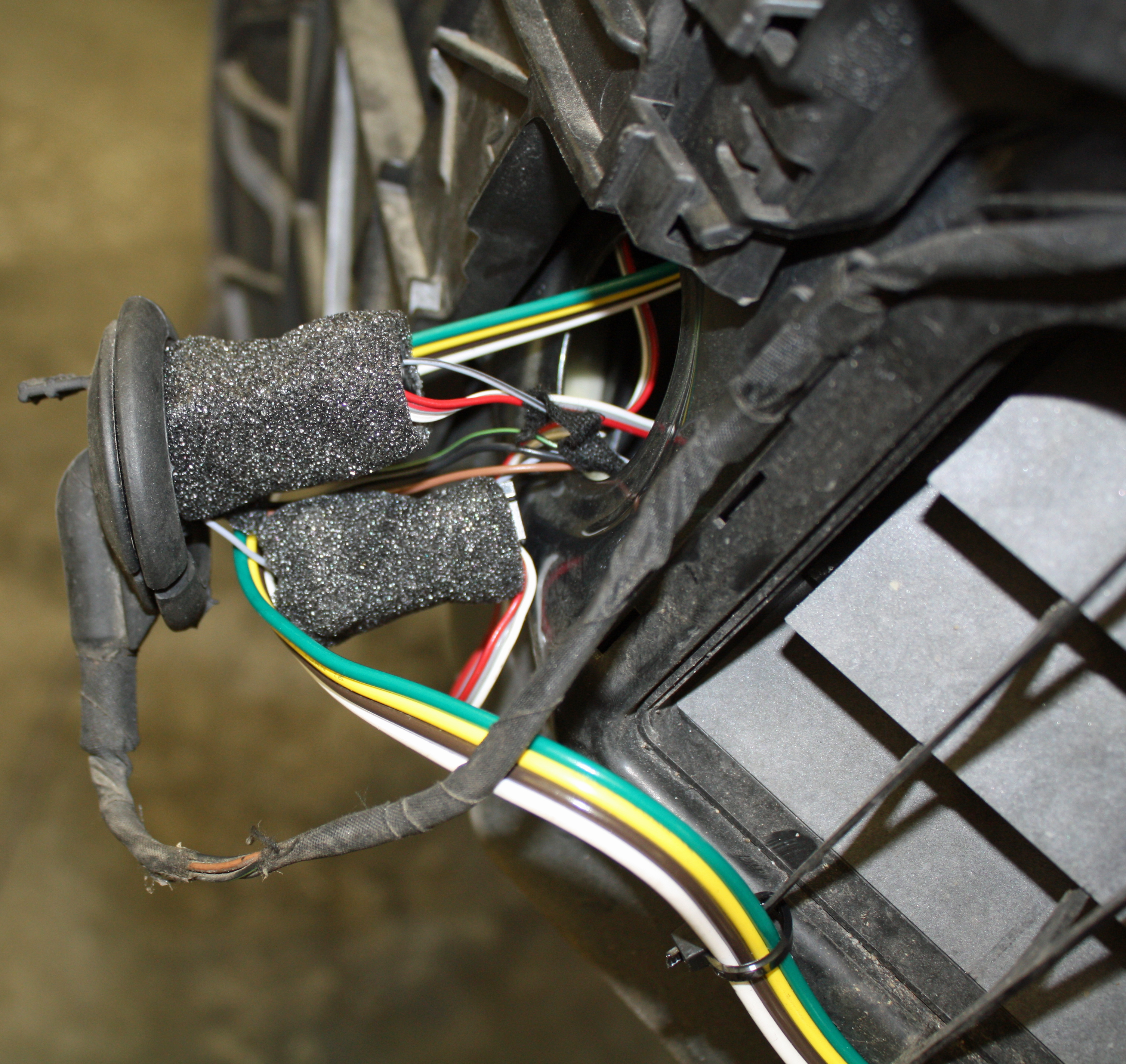
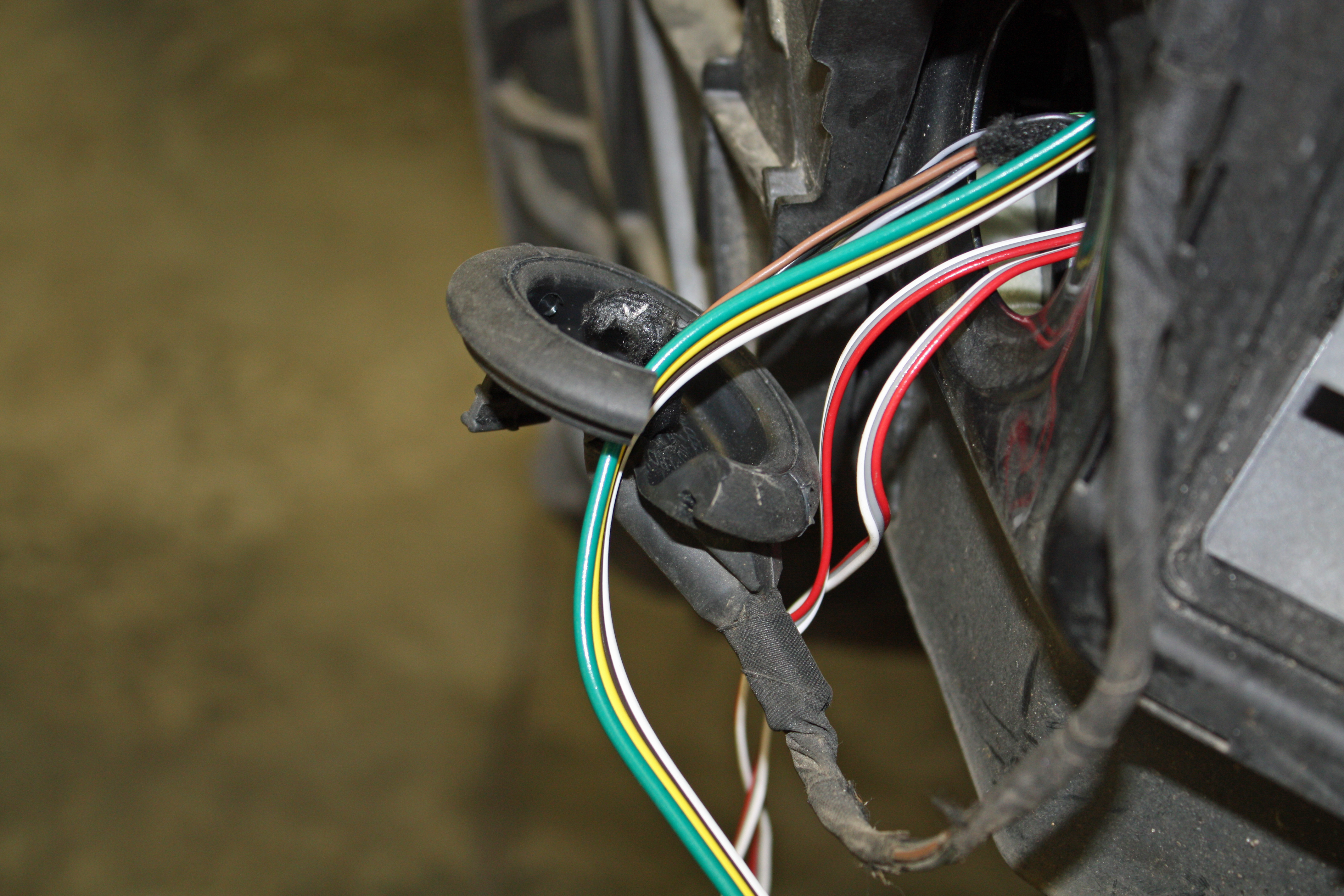
Since there wasn't a lot of room to access the taillight wires inside the car, I pulled the wiring harness through to the outside of the car. This is where I attached the module connectors. Be sure the arrow on the connector is aimed towards the taillight. Once you have the wire placed in the connector, you snap the cover closed. Once you are sure everything is working, the supplied adhesive backed foam is wrapped around the connector to hold everything in place.
There are four of these inductive connectors which are clearly marked: Left Turn Signal, Right Turn Signal, Brake, and Running Lights. Since the brake and turn signals use the same signal, the Brake connector was not used. I ran the left turn signal and running light connectors to the left side while the right turn signal connector was run across from the left side to the right side, as described above.
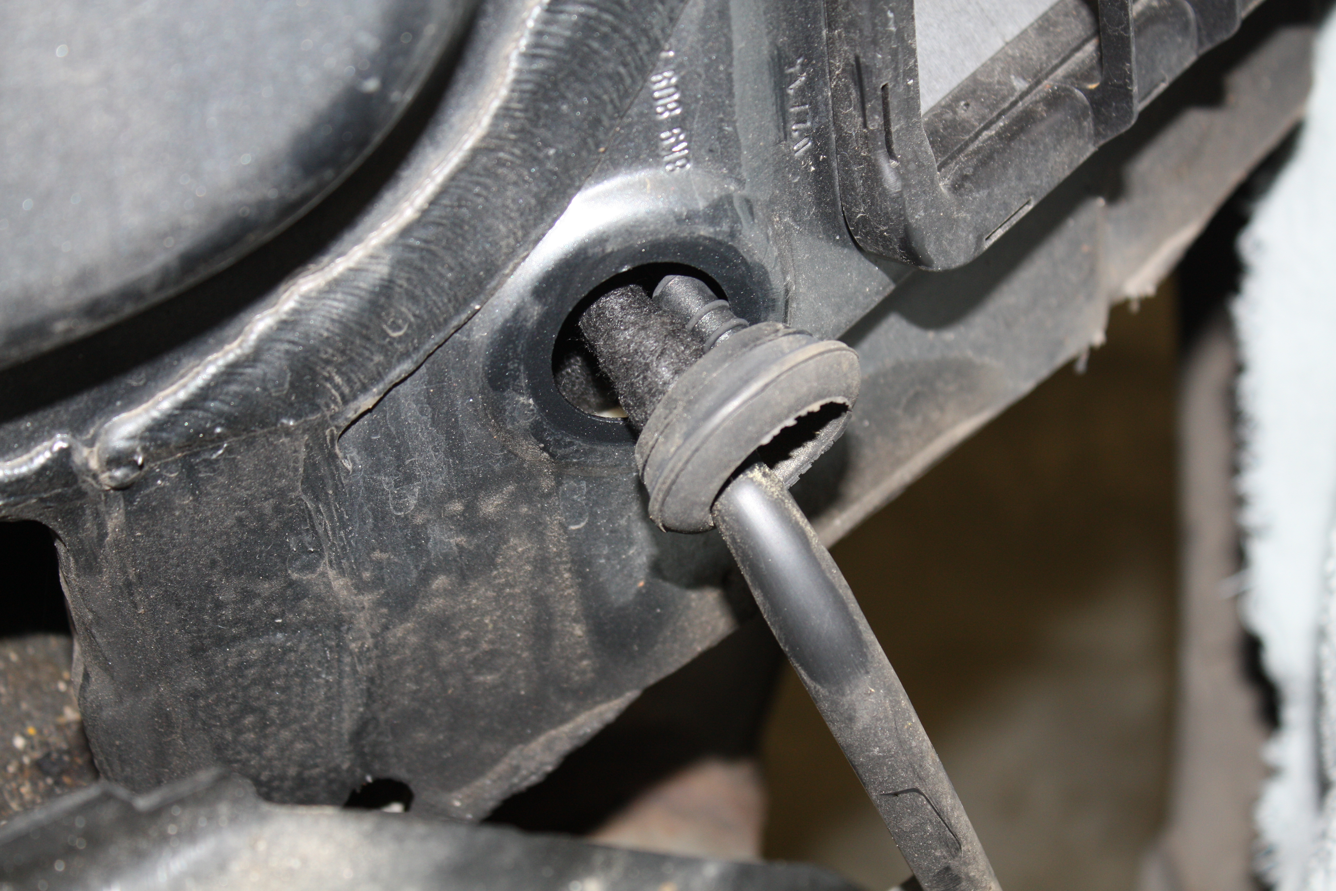
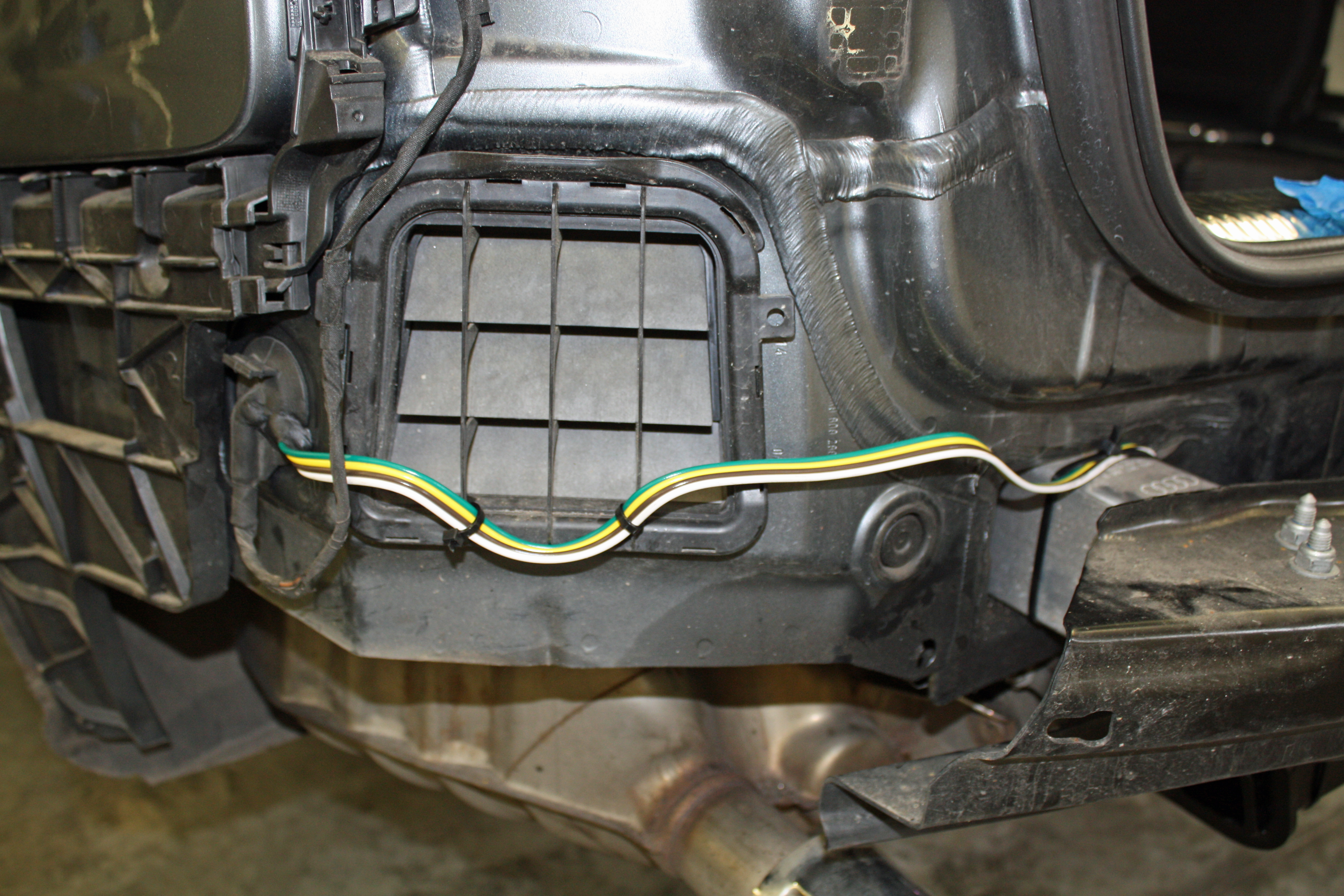
To run the trailer wiring harness from the module to the hitch, I slit the left side taillight wiring grommet and slipped it over the four wire trailer harness. I then ran the wires along the rear of the car to the hitch and zip tied the wires to the hitch, to a support and to the vent cover. With everything in place, I re-installed the grommets and applied rubber caulk to the left side grommet where I had slit it.
Now that the wiring was complete, it was time to re-assemble everything by reversing the steps above. That always sounds easier said than done, but, in this case, everything all went back together relatively easily. I have used the trailer a couple times and everything has worked well. I am very happy with the hitch as nothing hangs down and would recommend this hitch to anyone thinking of adding one.
Excellent! This solution is essentially the same conclusion I came to in the other thread, especially since no splicing (aka warranty voiding) is required.
I was scared to take the plunge, glad to see this is a workable solution!
I called all the Audi dealers in the area and everybody said it was not doable.
Just finished with my hitch and wiring project!! Took about 5 hours and the help of a friend who used to work in a garage. Could not have done it without your write-up and pics!! And really like the look and finish of the EcoHitch.
I was a little confused with the wiring part. Not used to having White as a ground wire. And I just ran the ground to a spot in the same compartment rather than to the battery.
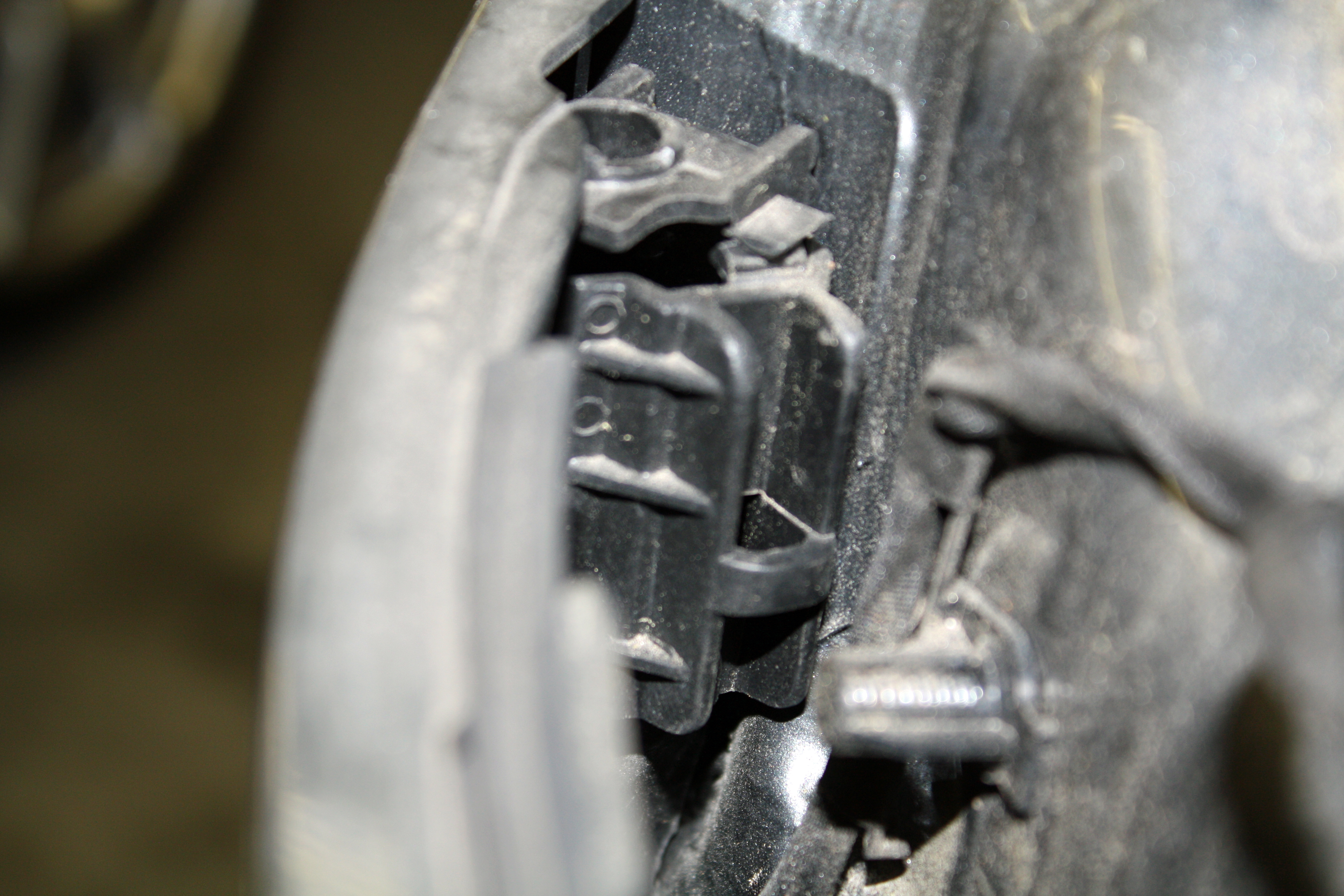
One minor addition - there was also one pop-up fastener that had to be removed just inside the wheel well lining in addition to the 3 screws and one flat clip. You can sort of see it in the picture of the wheel lining where one part of the bumper connects with the body.
Just finished with my hitch and wiring project!! Took about 5 hours and the help of a friend who used to work in a garage. Could not have done it without your write-up and pics!! And really like the look and finish of the EcoHitch.
I was a little confused with the wiring part. Not used to having White as a ground wire. And I just ran the ground to a spot in the same compartment rather than to the battery.
One minor addition - there was also one pop-up fastener that had to be removed just inside the wheel well lining in addition to the 3 screws and one flat clip. You can sort of see it in the picture of the wheel lining where one part of the bumper connects with the body.
Glad my post was helpful. Having it mostly hidden is the part I like best about this hitch.
Nice work on the tutorial! I was able to do mine in about 4hours, thanks to your clear guide. I'll share that I routed the pigtail through a hole that's near the hitch, just above the crossbar near the center of the car. There's a rubber plUg, which I pushed out, cut a slit in the center, and pushed the trailer plug through it. This way, there isn't as much wire to route across the rear of the car. Either way works great! And I was shocked how easy it was to work with the tekonsha device. Worked perfectly the first try.
To those who have wondered, this is very doable. Just be patient and you can do it. Now to tow my toys...
Nice work on the tutorial! I was able to do mine in about 4hours, thanks to your clear guide. I'll share that I routed the pigtail through a hole that's near the hitch, just above the crossbar near the center of the car. There's a rubber plUg, which I pushed out, cut a slit in the center, and pushed the trailer plug through it. This way, there isn't as much wire to route across the rear of the car. Either way works great! And I was shocked how easy it was to work with the tekton she device. Worked perfectly the first try.
To those who have wondered, this is very doable. Just be patient and you can do it. Now to tow my toys...
Thank you for sharing this. I use my hitch exclusively for a bike rack. I bought a Curt hitch for my B7 S4 Avant, cut off the 1.25" hitch socket that was below the cross bar, welded on a 2" hitch above the cross bar, and cut my valence. Placing it higher like this was essential for me to not scrape driveways, etc. See my pic below.
I just bought a B9 allroad, so I'm wondering if it's possible to do something similar? Specifically, and it's a little hard to tell from your photos, but is there any way to:
1) mount the hitch flush with the cross bar (vs the 1" drop or so?)
2) above the cross bar (is there enough room between the bumper and the cross bar?
 08-31-2016, 06:39 PM