When you click on links to various merchants on this site and make a purchase, this can result in this site earning a commission. Affiliate programs and affiliations include, but are not limited to, the eBay Partner Network.
Well obviously you folks got different options in your models, is that a 2.4l engine?
I saw that too on the CTS connector letter/number pin-out descriptions.
The info display should show a red overheat symbol as well and I'm not sure if that is on the cluster side of the CTS, probably so, but then a CEL would come on if the ECU side fails. German engineers are very meticulous and exact...bean counters are bean counters.
Yep, quite popular over here due to fuel economy. Not that the consupmtion is noticably different than the 2.8. Or so I've heard. And going by the forums, where the 2.4 is all but non-existant, I'm very thankful the 2.4 and 2.8 is almost indentical.
Btw - I posted the video of doing the cluster output test on the first thread page. Might want to take a look towards the end; it did NOT go through with the overheat test, and threw a "error or function not available" message ....not quite sure what to make of it.
Oh man, I think I need to have a look at this after a couple of hours of sleep. I could barely make out which one (G2/G62) gronds at the cluster. The gauge part made no sense.
TBH, I hadn't seen this type of diagram until a couple of days ago, slowly attempting to figure out "gremlins" with heated seat, power windows, heating side mirror etc (all driver side) - but thats a different story. This is my first post-95, "proper" car - all before them have been simpler and older, Opels and Hondas. So over the years I started to get the hang of the Haynes manual diagrams. These VAG diagrams are different animals, so a slight learning curve. Have to wrap my head around these different break-ups, tracks and number referrals.
Should have stuck with electrics in tech college.
LOL! I know what you mean, I'm a 28yr refrigeration tech that has worked on some of the most current complex control systems known to man kind with schematic's that have made me feel like a 6th grader at first.
Well rested, thinking its about time to give it a go with the "new, new" CTS. I did some googl'ing (is that a correct expression? It should be.) - and came across these two on a a german A4/S4-forum:
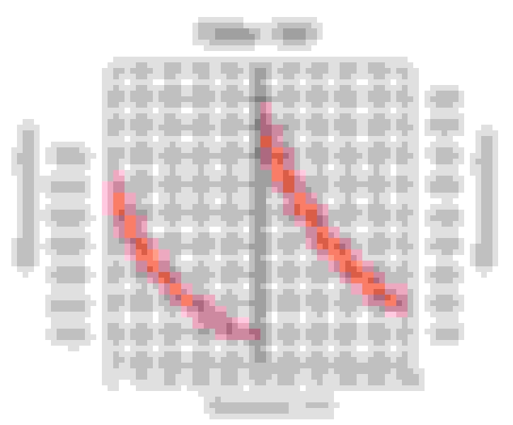
G62 thermistor resistance graph
G2 thermistor resistance graph
As I really have no way of officially confirming the G2 graph/values, this is still a guess of sorts - but the readings I got on the "G2 side", closely conforms to the graph here. Still about 5% on the plus side all along the graph, but that could be down to internal component tolerance... right? I mean, given the pricepoint, I'm not thrilled if VAG used 5% tolerance components for such an important task - but I wouldn't be falling off my chair in surprise either.
EDIT:
Also came across this. The pin numbering isn't the same (drawn on) , but the blocking does support the previous PDF from a test/wiring/measurement standpoint. Also - any views on why one terminal set seems to be brass/nickel, and the other aluminium/zinked?
Well rested, thinking its about time to give it a go with the "new, new" CTS. I did some googl'ing (is that a correct expression? It should be.) - and came across these two on a a german A4/S4-forum:
G62 thermistor resistance graph
G2 thermistor resistance graph
As I really have no way of officially confirming the G2 graph/values, this is still a guess of sorts - but the readings I got on the "G2 side", closely conforms to the graph here. Still about 5% on the plus side all along the graph, but that could be down to internal component tolerance... right? I mean, given the pricepoint, I'm not thrilled if VAG used 5% tolerance components for such an important task - but I wouldn't be falling off my chair in surprise either.
EDIT:
Also came across this. The pin numbering isn't the same (drawn on) , but the blocking does support the previous PDF from a test/wiring/measurement standpoint. Also - any views on why one terminal set seems to be brass/nickel, and the other aluminium/zinked?
G62 G2 CTS terminals
Wow! None of this makes sense, it appears that the Bentley diagram is not correct with pin-outs on the pic. I have noticed that some of the VW forum sites mention different configurations on the MK's and Passat's, disregarding single two pin sensors or dual three pin ones that have been used on some older 1.8 cars.
I'm also perplexed on the 4-pin G62 and G2 descriptions across the VAG forums on what is the ECU side and what is the Gauge.....I just can't imagine that there would be such difference's in a dual 4-pin sensor for North American models vs. UK/Europe models.
It also appears that the CTS test pdf right out of Bentley/Ebahn could be a little more descriptive why the sensor uses a low and high range ohm value, maybe that would be revealing a trade secret or something.
I can only speak for the square plug. The view of the plug has the same orientation in both the PDF and the img I posted. Pin numbering is different (would believe the PDF is correct, the img seems improvised for illustration), but the contact and wiring points are the same. The two on the right (sensor, PDF 1-3) is for the G62 part, ECM sensor - the two on the left, cluster. This conforms with both the PDF and the image. I've done some improvised re-wiring for test purposes today, so I know this is correct (for my car anyway).
Not quite sure why there are two different thermistors, and at different specs. But it must have been a concious choice, as the sensor has been revised since initial design, and as it is - failure of the G62 part has big consequences, but does not even throw a CEL.
What was going to be a 30 minute sensor swap, turned into a 7 hour mess. Got the CTS changed - after sitting 24 hours, G62 (ECM) side now reads within 2-3 degrees of ambient and intake temp. Yay! ... but - cluster still reads 30 degrees celsius. As both thermistors are reasonably within similar ranges, I improvised some leads and wired G62 output to G2 connector input. Still 30 degrees celsius. I pulled the plug all together..... still 30 degrees : (( - Not quite sure what to make of that - but the output test gauge part worked fine'ish... (?)
Also, vacuum leaks. Many, big ones. Plugged the intake and blew smoke in the fuel regulator vacuum line. Pretty much every union and plug along the brand new spider hose were fuming. Got them sealed eventually, but don't know of it'll last. To top it off, smoke showed a significant leak where the plastic intake plenum meets the throttle body.
As an added bonus - all sparkplugs black and marinated in oil, no real sign of leaking from the valve cover plughole gaskets. I changed the jet pump, spider hose and valve cover gaskets (plus newer type oil cap with pressure valve) 2 weeks ago as the jet pump was clogged - any idea how long it will usually take for any oil spill to burn off the plugs? Haven't used the car much since then.
I can only speak for the square plug. The view of the plug has the same orientation in both the PDF and the img I posted. Pin numbering is different (would believe the PDF is correct, the img seems improvised for illustration), but the contact and wiring points are the same. The two on the right (sensor, PDF 1-3) is for the G62 part, ECM sensor - the two on the left, cluster. This conforms with both the PDF and the image. I've done some improvised re-wiring for test purposes today, so I know this is correct (for my car anyway).
Not quite sure why there are two different thermistors, and at different specs. But it must have been a concious choice, as the sensor has been revised since initial design, and as it is - failure of the G62 part has big consequences, but does not even throw a CEL.
What was going to be a 30 minute sensor swap, turned into a 7 hour mess. Got the CTS changed - after sitting 24 hours, G62 (ECM) side now reads within 2-3 degrees of ambient and intake temp. Yay! ... but - cluster still reads 30 degrees celsius. As both thermistors are reasonably within similar ranges, I improvised some leads and wired G62 output to G2 connector input. Still 30 degrees celsius. I pulled the plug all together..... still 30 degrees : (( - Not quite sure what to make of that - but the output test gauge part worked fine'ish... (?)
Also, vacuum leaks. Many, big ones. Plugged the intake and blew smoke in the fuel regulator vacuum line. Pretty much every union and plug along the brand new spider hose were fuming. Got them sealed eventually, but don't know of it'll last. To top it off, leaking intake gasket/seal.
As an added bonus - all sparkplugs black and marinated in oil, no real sign of leaking from the valve cover plughole gaskets. I changed the jet pump, spider hose and valve cover gaskets (plus newer type oil cap with pressure valve) 2 weeks ago as the jet pump was clogged - any idea how long it will usually take for any oil spill to burn off the plugs? Haven't used the car much since then.
What pdf is correct? I'm confused because even the test Bentley's pdf shows 1-3 to be tested on the left side of the sensor for the ecu temp and your saying on the right side? There seems to be a slight contradiction in the first sentence on what is correct by what I've provided or what you have presented.
I changed my CTS in one hour on my 3.0 and I have meat-hook hands, but then I work on equipment all day long. Glad to hear the ecu side is working you're gas mileage should improve with proper mapping now especially finding and repairing vac leaks too.
The temp gauge issue: Seems that the test procedure claims that if 1-3 are jumpered on the harness connector that vagcom should see 140c, did you try 2-4 to see if the gauge responds?
If all the plugs are firing with a normal fuel trim and vac those plugs should tan-out if not new ones are in order.....sometimes driving it like you stole it helps too.
D'oh! My apologies. I reorganised the sentence mid way, and got it scr*wed up. I was referring to page 7 of the PDF (from Bentley) that you posted on thread page 1 - output shown there (pin 1-3, left side by orientation, is for G62/ECM. And that is all the PDF covers. The remaining pins, 2-4, would be the thermistor for the cluster.
Didn't try jumping 2-4, I was a little reluctant as it wasn't covered in the procedure, and I don't know if the circuit is fused. Don't want to fry a cluster because I went shorting out connections without doing my homework properly.
I'm not familiar with the layout of the 3.0 - but with the 2.4 its a matter of pulling the airbox whole and duct to grille and throttle plenum, unclip the fuel hoses from the plastic bracket and a few plugs along the way. Then I can squeeze my hand in from the side. The plastic engine covers have been of due to regular work in the engine bay lately.
I'll have to keep an eye on those plugs for a while then. Should get a compression tester, but I fear I might not like what it'll show.
 03-23-2015, 06:38 PM