Power Steering Suction Hose
 03-15-2013, 09:38 AM
#1
Audiworld Junior Member
Thread Starter

Join Date: Mar 2013
Location: Littleton, CO
Posts: 23
Likes: 0
Received 0 Likes
on
0 Posts
Does anyone have a diagram or picture of where this is? The dealership says its leaking and they want $250 to replace it. I think I can handle a hose swap.
2005 A6 3.2Q
2005 A6 3.2Q
 03-15-2013, 10:38 AM
#2

I'd suggest you get yourself a Bentley http://www.bentleypublishers.com/aud...009-ebahn.html , if you are planning on doing work on your car.
You'll save hassle with posting and waiting for replies, as well as have more complete details involving any work you are looking to under take.
I'm at work now, but have the schematic your looking for at home...will try to get it over the weekend, if possible.
You'll save hassle with posting and waiting for replies, as well as have more complete details involving any work you are looking to under take.
I'm at work now, but have the schematic your looking for at home...will try to get it over the weekend, if possible.
03-15-2013, 11:38 AM
#4
AudiWorld Senior Member
<TABLE class="cc abstand-kap einzug-standard"><TBODY><TR><TD class=titel-kap>Exploded view (vehicles with 6-cylinder 2.4 ltr., 2.8 ltr., 3.2 ltr. petrol and 3.0 ltr. TFSI engine)</TD></TR></TBODY></TABLE><TABLE class="cc einzug-standard abstand-standard "><TBODY><TR><TD>There is no provision for repairing the power steering pump. If problems are reported, trace the fault by means of a pressure test and a leakage test. Renew the power steering pump if there is a fault.</TD></TR></TBODY></TABLE>
Note
<TABLE class="cc abstand-liste einzug-standard hinweis-rumpf"><TBODY><TR><TD class=einzug-liste> </TD><TD>The power steering pump is supplied without fluid filling. Prior to installation, the pump must therefore always be filled with hydraulic fluid and turned by hand. Otherwise, there is a possibility of pump damage or noise while driving.
</TD></TR></TBODY></TABLE>
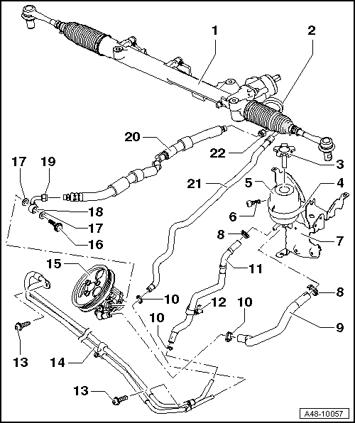
<TABLE class="cc abstand-standard erlaeutrg-explo"><TBODY><TR><TD class=einzug-nummer>1 - </TD><TD>Power steering box</TD></TR></TBODY></TABLE><TABLE class="cc einzug-explo abstand-explo "><TBODY><TR><TD class=einzug-liste>q </TD><TD>For correct version refer to → Electronic parts catalogue</TD></TR></TBODY></TABLE><TABLE class="cc abstand-standard erlaeutrg-explo"><TBODY><TR><TD class=einzug-nummer>2 - </TD><TD>Pressure hose</TD></TR></TBODY></TABLE><TABLE class="cc einzug-explo abstand-explo "><TBODY><TR><TD class=einzug-liste>q </TD><TD>Note correct position on steering box → Fig.</TD></TR></TBODY></TABLE><TABLE class="cc abstand-standard erlaeutrg-explo"><TBODY><TR><TD class=einzug-nummer>3 - </TD><TD>Cap with dipstick</TD></TR></TBODY></TABLE><TABLE class="cc einzug-explo abstand-explo "><TBODY><TR><TD class=einzug-liste>q </TD><TD>Checking fluid level → Chapter</TD></TR></TBODY></TABLE><TABLE class="cc abstand-standard erlaeutrg-explo"><TBODY><TR><TD class=einzug-nummer>4 - </TD><TD>Securing strap</TD></TR></TBODY></TABLE><TABLE class="cc abstand-standard erlaeutrg-explo"><TBODY><TR><TD class=einzug-nummer>5 - </TD><TD>Reservoir</TD></TR></TBODY></TABLE><TABLE class="cc einzug-explo abstand-explo "><TBODY><TR><TD class=einzug-liste>q </TD><TD>Note correct installation position → Chapter</TD></TR></TBODY></TABLE><TABLE class="cc abstand-standard erlaeutrg-explo"><TBODY><TR><TD class=einzug-nummer>6 - </TD><TD>Bolt</TD></TR></TBODY></TABLE><TABLE class="cc einzug-explo abstand-explo "><TBODY><TR><TD class=einzug-liste>q </TD><TD>9 Nm</TD></TR></TBODY></TABLE><TABLE class="cc abstand-standard erlaeutrg-explo"><TBODY><TR><TD class=einzug-nummer>7 - </TD><TD>Bracket</TD></TR></TBODY></TABLE><TABLE class="cc einzug-explo abstand-explo "><TBODY><TR><TD class=einzug-liste>q </TD><TD>For reservoir and ESP hydraulic unit</TD></TR></TBODY></TABLE><TABLE class="cc abstand-standard erlaeutrg-explo"><TBODY><TR><TD class=einzug-nummer>8 - </TD><TD>Spring-type clip</TD></TR></TBODY></TABLE><TABLE class="cc einzug-explo abstand-explo "><TBODY><TR><TD class=einzug-liste>q </TD><TD>Use spring-type clip pliers -VAS 5024 A- when removing and installing</TD></TR></TBODY></TABLE><TABLE class="cc abstand-standard erlaeutrg-explo"><TBODY><TR><TD class=einzug-nummer>9 - </TD><TD>Suction hose</TD></TR></TBODY></TABLE><TABLE class="cc einzug-explo abstand-explo "><TBODY><TR><TD class=einzug-liste>q </TD><TD>Note correct position on reservoir → Chapter</TD></TR></TBODY></TABLE><TABLE class="cc einzug-explo abstand-explo "><TBODY><TR><TD class=einzug-liste>q </TD><TD>Note correct position on power steering pump → Chapter</TD></TR></TBODY></TABLE><TABLE class="cc abstand-standard erlaeutrg-explo"><TBODY><TR><TD class=einzug-nummer>10 - </TD><TD>Hose clip</TD></TR></TBODY></TABLE><TABLE class="cc einzug-explo abstand-explo "><TBODY><TR><TD class=einzug-liste>q </TD><TD>Tighten using hose clip pliers -V.A.G 1275- or locking pliers for steering box -VAS 6199-</TD></TR></TBODY></TABLE><TABLE class="cc einzug-explo abstand-explo "><TBODY><TR><TD class=einzug-liste>q </TD><TD>Always renew</TD></TR></TBODY></TABLE><TABLE class="cc abstand-standard erlaeutrg-explo"><TBODY><TR><TD class=einzug-nummer>11 - </TD><TD>Return hose</TD></TR></TBODY></TABLE><TABLE class="cc einzug-explo abstand-explo "><TBODY><TR><TD class=einzug-liste>q </TD><TD>Note correct position on reservoir → Chapter</TD></TR></TBODY></TABLE><TABLE class="cc einzug-explo abstand-explo "><TBODY><TR><TD class=einzug-liste>q </TD><TD>Note attachment on longitudinal member → Fig.</TD></TR></TBODY></TABLE><TABLE class="cc abstand-standard erlaeutrg-explo"><TBODY><TR><TD class=einzug-nummer>12 - </TD><TD>Bracket</TD></TR></TBODY></TABLE><TABLE class="cc einzug-explo abstand-explo "><TBODY><TR><TD class=einzug-liste>q </TD><TD>Clipped onto longitudinal member</TD></TR></TBODY></TABLE><TABLE class="cc abstand-standard erlaeutrg-explo"><TBODY><TR><TD class=einzug-nummer>13 - </TD><TD>Bolt</TD></TR></TBODY></TABLE><TABLE class="cc einzug-explo abstand-explo "><TBODY><TR><TD class=einzug-liste>q </TD><TD>9 Nm</TD></TR></TBODY></TABLE><TABLE class="cc abstand-standard erlaeutrg-explo"><TBODY><TR><TD class=einzug-nummer>14 - </TD><TD>Cooling pipe</TD></TR></TBODY></TABLE><TABLE class="cc abstand-standard erlaeutrg-explo"><TBODY><TR><TD class=einzug-nummer>15 - </TD><TD>Power steering pump</TD></TR></TBODY></TABLE><TABLE class="cc einzug-explo abstand-explo "><TBODY><TR><TD class=einzug-liste>q </TD><TD>For correct version refer to → Electronic parts catalogue</TD></TR></TBODY></TABLE><TABLE class="cc einzug-explo abstand-explo "><TBODY><TR><TD class=einzug-liste>q </TD><TD>Fill with hydraulic fluid before installing</TD></TR></TBODY></TABLE><TABLE class="cc einzug-explo abstand-explo "><TBODY><TR><TD class=einzug-liste>q </TD><TD>Checking delivery pressure → Chapter</TD></TR></TBODY></TABLE><TABLE class="cc einzug-explo abstand-explo "><TBODY><TR><TD class=einzug-liste>q </TD><TD>Removing and installing → Anchor</TD></TR></TBODY></TABLE><TABLE class="cc abstand-standard erlaeutrg-explo"><TBODY><TR><TD class=einzug-nummer>16 - </TD><TD>Banjo bolt</TD></TR></TBODY></TABLE><TABLE class="cc einzug-explo abstand-explo "><TBODY><TR><TD class=einzug-liste>q </TD><TD>50 Nm</TD></TR></TBODY></TABLE><TABLE class="cc abstand-standard erlaeutrg-explo"><TBODY><TR><TD class=einzug-nummer>17 - </TD><TD>Seal</TD></TR></TBODY></TABLE><TABLE class="cc einzug-explo abstand-explo "><TBODY><TR><TD class=einzug-liste>q </TD><TD>Always renew</TD></TR></TBODY></TABLE><TABLE class="cc abstand-standard erlaeutrg-explo"><TBODY><TR><TD class=einzug-nummer>18 - </TD><TD>Pressure hose</TD></TR></TBODY></TABLE><TABLE class="cc einzug-explo abstand-explo "><TBODY><TR><TD class=einzug-liste>q </TD><TD>Note correct position on power steering pump → Chapter</TD></TR></TBODY></TABLE><TABLE class="cc abstand-standard erlaeutrg-explo"><TBODY><TR><TD class=einzug-nummer>19 - </TD><TD>Union nut</TD></TR></TBODY></TABLE><TABLE class="cc einzug-explo abstand-explo "><TBODY><TR><TD class=einzug-liste>q </TD><TD>40 Nm</TD></TR></TBODY></TABLE><TABLE class="cc abstand-standard erlaeutrg-explo"><TBODY><TR><TD class=einzug-nummer>20 - </TD><TD>Pressure hose</TD></TR></TBODY></TABLE><TABLE class="cc einzug-explo abstand-explo "><TBODY><TR><TD class=einzug-liste>q </TD><TD>Note correct position on steering box → Fig.</TD></TR></TBODY></TABLE><TABLE class="cc abstand-standard erlaeutrg-explo"><TBODY><TR><TD class=einzug-nummer>21 - </TD><TD>Return hose</TD></TR></TBODY></TABLE><TABLE class="cc einzug-explo abstand-explo "><TBODY><TR><TD class=einzug-liste>q </TD><TD>Note correct position on steering box → Fig.</TD></TR></TBODY></TABLE><TABLE class="cc einzug-explo abstand-explo "><TBODY><TR><TD class=einzug-liste>q </TD><TD>Note installation position on longitudinal member → Fig.</TD></TR></TBODY></TABLE><TABLE class="cc einzug-explo abstand-explo "><TBODY><TR><TD class=einzug-liste>q </TD><TD>Note attachment on longitudinal member → Fig.</TD></TR></TBODY></TABLE><TABLE class="cc abstand-standard erlaeutrg-explo"><TBODY><TR><TD class=einzug-nummer>22 - </TD><TD>Union nut</TD></TR></TBODY></TABLE><TABLE class="cc einzug-explo abstand-explo "><TBODY><TR><TD class=einzug-liste>q </TD><TD>40 Nm</TD></TR></TBODY></TABLE>
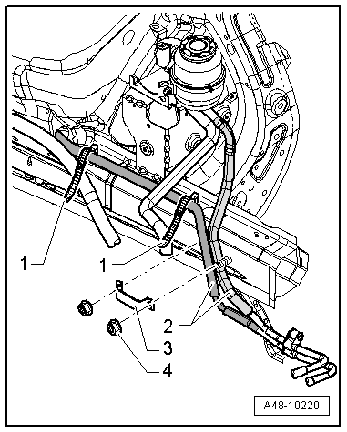
<TABLE class="cc bild-titel einzug-standard abstand-standard"><TBODY><TR><TD>Attachment of return hoses on longitudinal member</TD></TR></TBODY></TABLE><TABLE class="cc einzug-standard abstand-standard "><TBODY><TR><TD class=einzug-liste>� </TD><TD>Insert return hoses between studs.</TD></TR></TBODY></TABLE><TABLE class="cc einzug-standard abstand-standard "><TBODY><TR><TD class=einzug-liste>� </TD><TD>Secure return hoses -2- on longitudinal member with bracket -3- and nuts -4-.</TD></TR></TBODY></TABLE><TABLE class="cc einzug-standard abstand-standard "><TBODY><TR><TD class=einzug-liste></TD><TD>Tightening torque for nuts -2-: 2 Nm.</TD></TR></TBODY></TABLE><TABLE class="cc einzug-standard abstand-standard "><TBODY><TR><TD class=einzug-liste>� </TD><TD>Secure return hoses -2- on longitudinal member with cable tie -1-.</TD></TR></TBODY></TABLE>
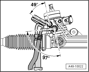
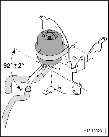
Position of pipe connections on steering box
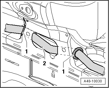
<TABLE class="cc bild-titel einzug-standard abstand-standard"><TBODY><TR><TD>Installation position in longitudinal member</TD></TR></TBODY></TABLE><TABLE class="cc einzug-standard abstand-standard "><TBODY><TR><TD class=einzug-liste>� </TD><TD>Engage guide bushes -1- in longitudinal member.</TD></TR></TBODY></TABLE><TABLE class="cc einzug-standard abstand-standard "><TBODY><TR><TD class=einzug-liste>� </TD><TD>Guide return hose -2- through support after installing bushes -1-.</TD></TR></TBODY></TABLE>
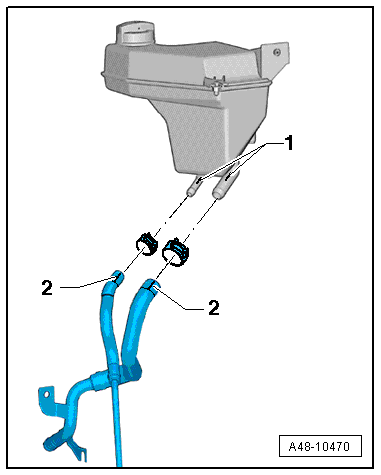
<TABLE cellSpacing=0 cellPadding=0 width="100%"><TBODY><TR><TD class=spalte-text><TABLE class="cc abstand-kap einzug-standard"><TBODY><TR><TD class=titel-kap>Installation position of fluid reservoir, position of suction hoses on reservoir</TD></TR></TBODY></TABLE></TD><TD class=spalte-pfeil></TD><TD class=spalte-marg></TD></TR></TBODY></TABLE><TABLE cellSpacing=0 cellPadding=0 width="100%"><TBODY><TR><TD class=spalte-text><TABLE class="cc einzug-standard abstand-standard absatz-hervor"><TBODY><TR><TD>Installation position of reservoir at bracket - applicable to all engines except 10-cylinder TFSI</TD></TR></TBODY></TABLE><TABLE class="cc einzug-standard abstand-standard "><TBODY><TR><TD class=einzug-liste>� </TD><TD>Install fluid reservoir on bracket for ESP hydraulic unit as shown in illustration.</TD></TR></TBODY></TABLE>
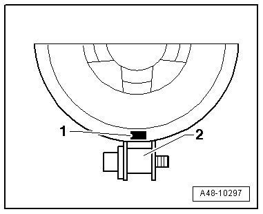
<TABLE class="cc bild-titel einzug-standard abstand-standard"><TBODY><TR><TD>Installation position of reservoir in bracket</TD></TR></TBODY></TABLE><TABLE class="cc einzug-standard abstand-standard "><TBODY><TR><TD class=einzug-liste>� </TD><TD>Install reservoir in securing strap as illustrated.</TD></TR></TBODY></TABLE><TABLE class="cc einzug-standard abstand-standard "><TBODY><TR><TD>Marking -1- must be in centre of clamp fastener -2-.</TD></TR></TBODY></TABLE>
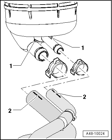
<TABLE class="cc einzug-standard abstand-standard absatz-hervor"><TBODY><TR><TD>Installation position of suction hose at reservoir - applicable to all engines except 10-cylinder TFSI</TD></TR></TBODY></TABLE><TABLE class="cc einzug-standard abstand-standard "><TBODY><TR><TD>The marks -2- on the hoses must coincide with the ribs -1- on the reservoir.</TD></TR></TBODY></TABLE>
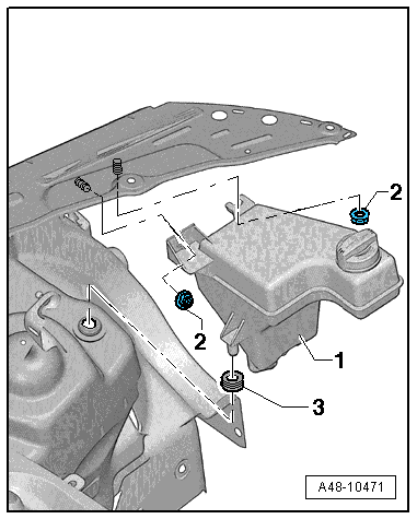
<TABLE class="cc einzug-standard abstand-standard absatz-hervor"><TBODY><TR><TD>Installation position of reservoir - applicable to 10-cylinder TFSI engines</TD></TR></TBODY></TABLE><TABLE class="cc einzug-standard abstand-standard "><TBODY><TR><TD>-1- Reservoir</TD></TR></TBODY></TABLE><TABLE class="cc einzug-standard abstand-standard "><TBODY><TR><TD>-2- Nut 8 Nm</TD></TR></TBODY></TABLE><TABLE class="cc einzug-standard abstand-standard "><TBODY><TR><TD>-3- Grommet</TD></TR></TBODY></TABLE>
<TABLE class="cc einzug-standard abstand-standard absatz-hervor"><TBODY><TR><TD>Installation position of suction hose at reservoir - applicable to 10-cylinder TFSI engines</TD></TR></TBODY></TABLE><TABLE class="cc einzug-standard abstand-standard "><TBODY><TR><TD>The lines -2- marked on the hoses must coincide with the markings -1- on the reservoir.</TD></TR></TBODY></TABLE>
<TABLE cellSpacing=0 cellPadding=0 width="100%"><TBODY><TR><TD class=spalte-text><TABLE class="cc abstand-kap einzug-standard"><TBODY><TR><TD class=titel-kap>Bleeding steering system after repairs</TD></TR></TBODY></TABLE><TABLE class="cc einzug-standard abstand-standard "><TBODY><TR><TD>Different bleeding procedures are required after repairs to the steering system, depending on which components have been removed or renewed.</TD></TR></TBODY></TABLE><TABLE class="cc einzug-standard abstand-standard absatz-hervor"><TBODY><TR><TD>Bleeding system after replacement of entire steering system or steering box:</TD></TR></TBODY></TABLE><TABLE class="cc einzug-standard abstand-standard "><TBODY><TR><TD class=einzug-liste>� </TD><TD>Fill reservoir completely.</TD></TR></TBODY></TABLE><TABLE class="cc einzug-standard abstand-standard absatz-hervor"><TBODY><TR><TD>Applies to 10-cylinder TFSI vehicles</TD></TR></TBODY></TABLE>Note
<TABLE class="cc abstand-liste-erster einzug-standard hinweis-rumpf"><TBODY><TR><TD>On 10-cylinder TFSI vehicles, the reservoir consists of 2 chambers separated by a strainer. To prevent incorrect filling, wait several minutes after filling or extraction for the level to even out in the 2 chambers.</TD></TR></TBODY></TABLE><TABLE class="cc einzug-standard abstand-standard absatz-hervor"><TBODY><TR><TD>All vehicles</TD></TR></TBODY></TABLE><TABLE class="cc einzug-standard abstand-standard "><TBODY><TR><TD class=einzug-liste>� </TD><TD>Raise vehicle so that all wheels are free.</TD></TR></TBODY></TABLE><TABLE class="cc abstand-standard einzug-standard "><TBODY><TR><TD class=einzug-liste>l </TD><TD>Engine switched off.</TD></TR></TBODY></TABLE><TABLE class="cc einzug-standard abstand-standard "><TBODY><TR><TD class=einzug-liste>� </TD><TD>With engine switched off, turn steering wheel 10 times from lock to lock.</TD></TR></TBODY></TABLE><TABLE class="cc einzug-standard abstand-standard "><TBODY><TR><TD class=einzug-liste>� </TD><TD>Fill reservoir completely.</TD></TR></TBODY></TABLE><TABLE class="cc einzug-standard abstand-standard "><TBODY><TR><TD class=einzug-liste>� </TD><TD>Start engine and let it run briefly (2 seconds maximum).</TD></TR></TBODY></TABLE><TABLE class="cc einzug-standard abstand-standard "><TBODY><TR><TD>Pump must not draw in air. Steering wheel must not be turned.</TD></TR></TBODY></TABLE><TABLE class="cc einzug-standard abstand-standard "><TBODY><TR><TD>Wait approx. 30 seconds between engine starts.</TD></TR></TBODY></TABLE><TABLE class="cc einzug-standard abstand-standard "><TBODY><TR><TD class=einzug-liste>� </TD><TD>Check hydraulic fluid level and top up if necessary.</TD></TR></TBODY></TABLE><TABLE class="cc einzug-standard abstand-standard "><TBODY><TR><TD class=einzug-liste>� </TD><TD>Keep repeating this procedure until fluid level remains constant.</TD></TR></TBODY></TABLE><TABLE class="cc einzug-standard abstand-standard "><TBODY><TR><TD class=einzug-liste>� </TD><TD>With engine switched off, turn steering wheel 10 times from lock to lock.</TD></TR></TBODY></TABLE><TABLE class="cc einzug-standard abstand-standard "><TBODY><TR><TD class=einzug-liste>� </TD><TD>Check hydraulic fluid level and top up if necessary.</TD></TR></TBODY></TABLE><TABLE class="cc einzug-standard abstand-standard "><TBODY><TR><TD class=einzug-liste>� </TD><TD>Start engine.</TD></TR></TBODY></TABLE><TABLE class="cc einzug-standard abstand-standard "><TBODY><TR><TD class=einzug-liste>� </TD><TD>Turn steering wheel 10 times from lock to lock.</TD></TR></TBODY></TABLE><TABLE class="cc einzug-standard abstand-standard "><TBODY><TR><TD class=einzug-liste>� </TD><TD>Check hydraulic fluid level and top up if necessary.</TD></TR></TBODY></TABLE><TABLE class="cc einzug-standard abstand-standard "><TBODY><TR><TD>Any air remaining in the steering system will dissipate when the vehicle has been driven 10�20 km.</TD></TR></TBODY></TABLE><TABLE class="cc einzug-standard abstand-standard absatz-hervor"><TBODY><TR><TD>Bleeding system after removing one or more steering system components with the exception of the steering box (i.e. pump, hoses, etc.):</TD></TR></TBODY></TABLE><TABLE class="cc einzug-standard abstand-standard "><TBODY><TR><TD class=einzug-liste>� </TD><TD>Check hydraulic fluid level and top up if necessary → Chapter.</TD></TR></TBODY></TABLE><TABLE class="cc einzug-standard abstand-standard absatz-hervor"><TBODY><TR><TD>Applies to 10-cylinder TFSI vehicles</TD></TR></TBODY></TABLE>Note
<TABLE class="cc abstand-liste-erster einzug-standard hinweis-rumpf"><TBODY><TR><TD>On 10-cylinder TFSI vehicles, the reservoir consists of 2 chambers separated by a strainer. To prevent incorrect filling of the reservoir, wait several minutes after filling or extraction for the level to even out in the 2 chambers.</TD></TR></TBODY></TABLE><TABLE class="cc einzug-standard abstand-standard absatz-hervor"><TBODY><TR><TD>All vehicles</TD></TR></TBODY></TABLE><TABLE class="cc einzug-standard abstand-standard "><TBODY><TR><TD class=einzug-liste>� </TD><TD>Start engine and let it run briefly (2 seconds maximum).</TD></TR></TBODY></TABLE><TABLE class="cc einzug-standard abstand-standard "><TBODY><TR><TD>Pump must not draw in air; steering wheel must not be turned.</TD></TR></TBODY></TABLE><TABLE class="cc einzug-standard abstand-standard "><TBODY><TR><TD>Wait approx. 30 seconds between engine starts.</TD></TR></TBODY></TABLE><TABLE class="cc einzug-standard abstand-standard "><TBODY><TR><TD class=einzug-liste>� </TD><TD>Check hydraulic fluid level and top up if necessary.</TD></TR></TBODY></TABLE><TABLE class="cc einzug-standard abstand-standard "><TBODY><TR><TD class=einzug-liste>� </TD><TD>Keep repeating this procedure until fluid level remains constant.</TD></TR></TBODY></TABLE><TABLE class="cc einzug-standard abstand-standard "><TBODY><TR><TD class=einzug-liste>� </TD><TD>Start engine and let it run for 2 - 3 minutes without turning steering wheel.</TD></TR></TBODY></TABLE><TABLE class="cc einzug-standard abstand-standard "><TBODY><TR><TD class=einzug-liste>� </TD><TD>Check hydraulic fluid level and top up if necessary.</TD></TR></TBODY></TABLE><TABLE class="cc einzug-standard abstand-standard "><TBODY><TR><TD>Any air remaining in the steering system will dissipate when the vehicle has been driven 10�20 km.</TD></TR></TBODY></TABLE>
</TD></TR></TBODY></TABLE>
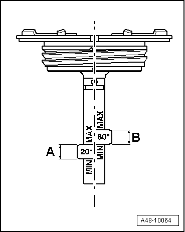
<TABLE cellSpacing=0 cellPadding=0 width="100%"><TBODY><TR><TD class=spalte-text><TABLE class="cc abstand-kap einzug-standard"><TBODY><TR><TD class=titel-kap>Checking power steering fluid level (all engines except 10-cylinder TFSI)</TD></TR></TBODY></TABLE><TABLE class="cc einzug-standard abstand-standard "><TBODY><TR><TD class=einzug-liste>� </TD><TD>Do not start engine. Set front wheels to straight-ahead position.</TD></TR></TBODY></TABLE><TABLE class="cc einzug-standard abstand-standard "><TBODY><TR><TD></TD></TR></TBODY></TABLE><TABLE class="cc einzug-standard abstand-standard absatz-hervor"><TBODY><TR><TD>When fluid is cold (approx. 20�C):</TD></TR></TBODY></TABLE><TABLE class="cc einzug-standard abstand-standard "><TBODY><TR><TD class=einzug-liste>� </TD><TD>Unscrew filler cap.</TD></TR></TBODY></TABLE><TABLE class="cc einzug-standard abstand-standard "><TBODY><TR><TD class=einzug-liste>� </TD><TD>Wipe dipstick with a clean cloth.</TD></TR></TBODY></TABLE><TABLE class="cc einzug-standard abstand-standard "><TBODY><TR><TD class=einzug-liste>� </TD><TD>Screw filler cap on hand tight and unscrew again.</TD></TR></TBODY></TABLE>Note
<TABLE class="cc abstand-liste-erster einzug-standard hinweis-rumpf"><TBODY><TR><TD>The cap must first be fully screwed on in order to obtain an accurate fluid level reading.</TD></TR></TBODY></TABLE>
</TD><TD class=spalte-pfeil></TD><TD class=spalte-marg></TD></TR></TBODY></TABLE><TABLE cellSpacing=0 cellPadding=0 width="100%"><TBODY><TR><TD class=spalte-text><TABLE class="cc einzug-standard abstand-standard "><TBODY><TR><TD class=einzug-liste>� </TD><TD>Check fluid level: fluid level should be in area -A-.
</TD></TR></TBODY></TABLE><TABLE class="cc einzug-standard abstand-standard absatz-hervor"><TBODY><TR><TD>When fluid is at operating temperature (approx. 80 �C):</TD></TR></TBODY></TABLE><TABLE class="cc einzug-standard abstand-standard "><TBODY><TR><TD class=einzug-liste>� </TD><TD>Unscrew filler cap.</TD></TR></TBODY></TABLE><TABLE class="cc einzug-standard abstand-standard "><TBODY><TR><TD class=einzug-liste>� </TD><TD>Wipe dipstick with a clean cloth.</TD></TR></TBODY></TABLE><TABLE class="cc einzug-standard abstand-standard "><TBODY><TR><TD class=einzug-liste>� </TD><TD>Screw filler cap on hand tight and unscrew again.</TD></TR></TBODY></TABLE>Note
<TABLE class="cc abstand-liste-erster einzug-standard hinweis-rumpf"><TBODY><TR><TD>The cap must first be fully screwed on in order to obtain an accurate fluid level reading.
<TABLE cellSpacing=0 cellPadding=0 width="100%"><TBODY><TR><TD class=spalte-text><TABLE class="cc einzug-standard abstand-standard "><TBODY><TR><TD class=einzug-liste>� </TD><TD>Check fluid level: fluid level should be in area -B-.</TD></TR></TBODY></TABLE></TD></TR></TBODY></TABLE>
</TD></TR></TBODY></TABLE>
Note<TABLE class="cc abstand-liste-erster einzug-standard hinweis-rumpf"><TBODY><TR><TD class=einzug-liste>t </TD><TD>Excess fluid must be drained off if the level is above the range specified above.</TD></TR></TBODY></TABLE><TABLE class="cc abstand-liste einzug-standard hinweis-rumpf"><TBODY><TR><TD class=einzug-liste>t </TD><TD>If the fluid level is below the range specified, the hydraulic system must be checked for leaks. In this case it is not sufficient to merely top up the fluid.</TD></TR></TBODY></TABLE><TABLE class="cc abstand-liste einzug-standard hinweis-rumpf"><TBODY><TR><TD class=einzug-liste>t </TD><TD>Do not re-use hydraulic fluid which has been drained off.</TD></TR></TBODY></TABLE>
</TD></TR></TBODY></TABLE>
</TD></TR></TBODY></TABLE>
Last edited by royclark; 03-15-2013 at 01:26 PM.
03-15-2013, 10:24 PM
#6
AudiWorld Member

You don't need a new hose. All you need is a new hose clamp where it connects to the cooler pipe to replace a band clamp. You will see where it leaks when you remove the splash guard.
Don't use power steering fluid or atf if you need to top it off. It needs specfic gear oil
Bonus: my favorite German hose clamp source for my Audi and BMW here.
https://www.belmetric.com/metric-cla...-c-15_145.html
Last edited by audi bug; 03-15-2013 at 10:28 PM.
03-18-2013, 07:37 AM
#7
Audiworld Junior Member
Thread Starter
Join Date: Mar 2013
Location: Littleton, CO
Posts: 23
Likes: 0
Received 0 Likes
on
0 Posts
That's why they are called stealerships.
You don't need a new hose. All you need is a new hose clamp where it connects to the cooler pipe to replace a band clamp. You will see where it leaks when you remove the splash guard.
Don't use power steering fluid or atf if you need to top it off. It needs specfic gear oil
Bonus: my favorite German hose clamp source for my Audi and BMW here.
https://www.belmetric.com/metric-cla...-c-15_145.html
This site is great!

Thread
Thread Starter
Forum
Replies
Last Post
tabs80
Audi 90 / 80 / Coupe quattro / Cabriolet
2
11-15-2010 09:43 AM