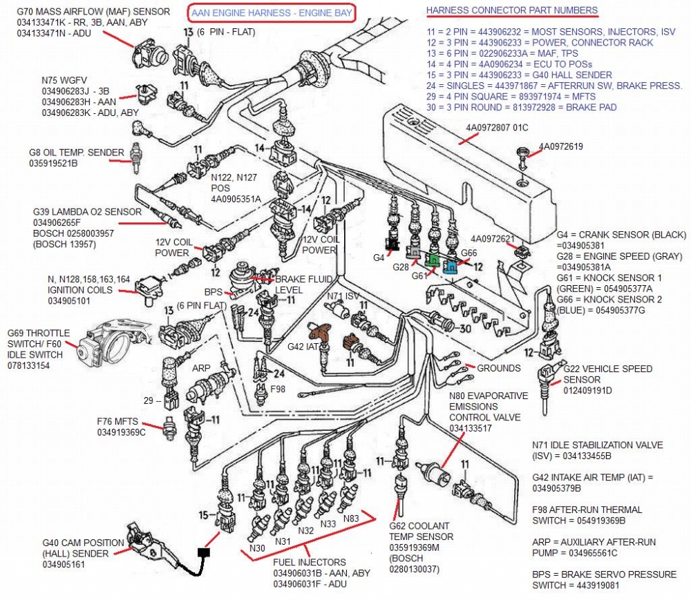
Audi S2 3B original wiring harness illustration
 09-18-2017, 07:29 AM
#1
AudiWorld Newcomer
Thread Starter

Join Date: Jan 2015
Posts: 9
Likes: 0
Received 0 Likes
on
0 Posts
I am asking for help in identifying Audi S2 3B original wiring harness illustration, Engine bay only ..coloring would be more appreciated
thanks in advance
thanks in advance
 09-19-2017, 07:03 AM
#2

Good luck. You won't find one. But try poking around S2Central.net Technical Welcome to S2 Central
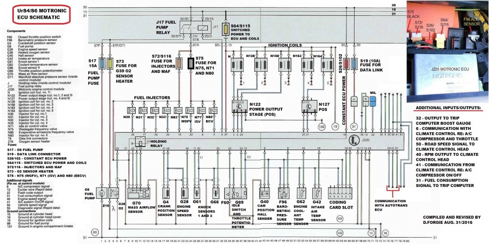
I've annotated a factory AAN diagrams but there isn't enough room to get colours on it. I had to do that with text in a description of the AAN ECU T55 pin-out (link under diagrams):
REFERENCE:
AAN Motronic ECU device list and T55 connector pin-outs (with wire colours) and hyperlinks:
quattroworld.com Forums: AAN Motronic ECU device list and T55 connector pin-outs (with wire colours) and hyperlinks

Last edited by UrS4boy; 09-19-2017 at 08:24 AM.
09-19-2017, 08:26 AM
#3
From S2 Central.net:
A diagram and a wire colour list (but not on one diagram):
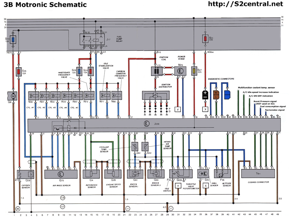
Motronic ECU Pinout for the 3B Engine
IMPORTANT - The information on this page is ONLY applicable to the 3B engine. It is NOT transferable to the ABY engine.
The image below depicts the pin locations as if viewing the connector on the ECU.
3B ECU pinput
The image below depicts the 3B ECU pinout when viewing the cable assembly.
ECU Cable
The following table defines the functionality of each of the 55 pins on the 3B Motronic ECU.
Pin Function / Assignment Input or Output wrt ECU Schematic References Wire Colour at ECU
01 Output stage for ignition coil
OUTPUT
N70 , Sheet #5 gn/ws
02 Coding plug (Territory details unknown)
INPUT
- ge/sw
03 Fuel pump relay control OUTPUT J17, G6 , Sheet #3 br/gn
04 Idle stabiliser control OUTPUT N71 , Sheet #5 gr/sw
05 Carbon canister frequency valve control OUTPUT N80 , Sheet #5 ws
06 Tachometer signal (to Instruments & Autocheck) OUTPUT Sheets #5, #7 & #8 li
07 Air mass sensor value (from G70 pin #3) INPUT G70 , Sheet #3 sw/ws
08 Hall effect sensor (signal wire from G40 pin #2) INPUT G40 , Sheet #5 gn
09 Not Used N/A - -
10 Ground #1 (0V) - Inlet manifold - Sheet #4 br/ge
11 Knock Sensor 1 INPUT G61 , Sheet #2 sw
12 Reference voltage (+ve) to throttle pot, hall effect sensor, altitude sensor and coding plug connector OUTPUT G69 , G40 , F96 , Sheets #3, #4 & #5 ro/sw
13 OBD signal (L-Wire) - White connector INPUT Sheet #2 sw/ws
14 Ground #2 (0V) - Inlet manifold - Sheet #4 br/ro
15 Fuel injector #3 control (switched 0V) OUTPUT N32 , Sheet #4 br/gn
16 Fuel injector #2 control (switched 0V) OUTPUT N31 , Sheet #4 br/bl
17 Fuel injector #1 control (switched 0V) OUTPUT N30 , Sheet #4 br/sw
18 +12V battery feed, via Fuse S27 INPUT Sheet #5 ro/ws
19 Ground #3 (0V) - Sheet #4 br/ge
20 Not Used N/A - -
21 Not Used N/A - -
22 OBD Signal (Blink Output / Malfunction Indication) - Blue connector OUTPUT Sheet #2 ?
23 Wastegate frequency valve control (switched 0V) OUTPUT N75 , Sheet #5 gn/ge
24 Ground #4 (0V)
- Sheet #4 br/ro
25 MAF Sensor (G70 Pin #4) OUTPUT G70 , Sheet #3 bl/li
26 MAF Sensor (G70 Pin #2) OUTPUT G70 , Sheet #3 ws/gn
27 +12V Ignition ON (Terminal 15) INPUT
Sheet #2 sw
28 Lambda sensor signal INPUT G39 , Sheet #3 ?
29 Knock Sensor 2
INPUT
G66 , Sheet #2
sw
30 0V Reference Signal - F96 , G42 , G61 ,G62, G66, G69 Sheets #2, #3 & #4
sw/li
31 Boost pressure signal for trip computer (Not used on S2)
OUTPUT
Sheet #3
-
32 Fuel consumption signal for trip computer (J128)
OUTPUT
Sheet #2
bl/sw
33 Not Used N/A - -
34 Fuel injector #5 control (switched 0V)
OUTPUT
N83 , Sheet #4
br/ro
35 Fuel injector #4 control (switched 0V)
OUTPUT N33 , Sheet #4
br/ws
36 Multifunction coolant temperature sensor, Pin #2 'R' INPUT F76, Sheets #2 & #8 bl/ws
37 +12V battery feed, via Fuse S28 INPUT Sheet #4 bl/sw
38 Coding plug (Territory details unknown) INPUT -
br/bl
39 Coding plug (Territory details unknown) INPUT -
ws/sw
40 A/C compressor ON/OFF indication INPUT
Sheet #2
gn/ge
41 A/C compressor - Idle speed increase indication INPUT Sheet #2 br/sw
42 Not Used N/A - -
43 Not Used N/A - -
44 Intake air temperature sensor INPUT G42 , Sheet #3 bl
45 Coolant temperature sensor INPUT G62 , Sheet #3
ro/gn
46 Altitude sensor INPUT F96 , Sheet #3 br
47 Engine speed sensor
INPUT G28 , Sheet #2 gr
48 Reference point for engine speed and crankshaft position sensors - G4 , G28 Sheet #2 ro & bl
49 Crankshaft position sensor INPUT G4 , Sheet #2 li
50 Not Used N/A - -
51 Not Used N/A - -
52 Idle throttle position switch (F60/G69 Pin #6) INPUT F60 , Sheet #4 gn/li
53 Throttle valve position (F60/G69 Pin #3) INPUT G69 , Sheet #4 gn/bl
54 Coding plug (Territory details unknown) INPUT - ro/ge
55 OBD signal (K-Wire) - White connector OUTPUT Sheet #2 ge/bl
A diagram and a wire colour list (but not on one diagram):
Motronic ECU Pinout for the 3B Engine
IMPORTANT - The information on this page is ONLY applicable to the 3B engine. It is NOT transferable to the ABY engine.
The image below depicts the pin locations as if viewing the connector on the ECU.
3B ECU pinput
The image below depicts the 3B ECU pinout when viewing the cable assembly.
ECU Cable
The following table defines the functionality of each of the 55 pins on the 3B Motronic ECU.
Pin Function / Assignment Input or Output wrt ECU Schematic References Wire Colour at ECU
01 Output stage for ignition coil
OUTPUT
N70 , Sheet #5 gn/ws
02 Coding plug (Territory details unknown)
INPUT
- ge/sw
03 Fuel pump relay control OUTPUT J17, G6 , Sheet #3 br/gn
04 Idle stabiliser control OUTPUT N71 , Sheet #5 gr/sw
05 Carbon canister frequency valve control OUTPUT N80 , Sheet #5 ws
06 Tachometer signal (to Instruments & Autocheck) OUTPUT Sheets #5, #7 & #8 li
07 Air mass sensor value (from G70 pin #3) INPUT G70 , Sheet #3 sw/ws
08 Hall effect sensor (signal wire from G40 pin #2) INPUT G40 , Sheet #5 gn
09 Not Used N/A - -
10 Ground #1 (0V) - Inlet manifold - Sheet #4 br/ge
11 Knock Sensor 1 INPUT G61 , Sheet #2 sw
12 Reference voltage (+ve) to throttle pot, hall effect sensor, altitude sensor and coding plug connector OUTPUT G69 , G40 , F96 , Sheets #3, #4 & #5 ro/sw
13 OBD signal (L-Wire) - White connector INPUT Sheet #2 sw/ws
14 Ground #2 (0V) - Inlet manifold - Sheet #4 br/ro
15 Fuel injector #3 control (switched 0V) OUTPUT N32 , Sheet #4 br/gn
16 Fuel injector #2 control (switched 0V) OUTPUT N31 , Sheet #4 br/bl
17 Fuel injector #1 control (switched 0V) OUTPUT N30 , Sheet #4 br/sw
18 +12V battery feed, via Fuse S27 INPUT Sheet #5 ro/ws
19 Ground #3 (0V) - Sheet #4 br/ge
20 Not Used N/A - -
21 Not Used N/A - -
22 OBD Signal (Blink Output / Malfunction Indication) - Blue connector OUTPUT Sheet #2 ?
23 Wastegate frequency valve control (switched 0V) OUTPUT N75 , Sheet #5 gn/ge
24 Ground #4 (0V)
- Sheet #4 br/ro
25 MAF Sensor (G70 Pin #4) OUTPUT G70 , Sheet #3 bl/li
26 MAF Sensor (G70 Pin #2) OUTPUT G70 , Sheet #3 ws/gn
27 +12V Ignition ON (Terminal 15) INPUT
Sheet #2 sw
28 Lambda sensor signal INPUT G39 , Sheet #3 ?
29 Knock Sensor 2
INPUT
G66 , Sheet #2
sw
30 0V Reference Signal - F96 , G42 , G61 ,G62, G66, G69 Sheets #2, #3 & #4
sw/li
31 Boost pressure signal for trip computer (Not used on S2)
OUTPUT
Sheet #3
-
32 Fuel consumption signal for trip computer (J128)
OUTPUT
Sheet #2
bl/sw
33 Not Used N/A - -
34 Fuel injector #5 control (switched 0V)
OUTPUT
N83 , Sheet #4
br/ro
35 Fuel injector #4 control (switched 0V)
OUTPUT N33 , Sheet #4
br/ws
36 Multifunction coolant temperature sensor, Pin #2 'R' INPUT F76, Sheets #2 & #8 bl/ws
37 +12V battery feed, via Fuse S28 INPUT Sheet #4 bl/sw
38 Coding plug (Territory details unknown) INPUT -
br/bl
39 Coding plug (Territory details unknown) INPUT -
ws/sw
40 A/C compressor ON/OFF indication INPUT
Sheet #2
gn/ge
41 A/C compressor - Idle speed increase indication INPUT Sheet #2 br/sw
42 Not Used N/A - -
43 Not Used N/A - -
44 Intake air temperature sensor INPUT G42 , Sheet #3 bl
45 Coolant temperature sensor INPUT G62 , Sheet #3
ro/gn
46 Altitude sensor INPUT F96 , Sheet #3 br
47 Engine speed sensor
INPUT G28 , Sheet #2 gr
48 Reference point for engine speed and crankshaft position sensors - G4 , G28 Sheet #2 ro & bl
49 Crankshaft position sensor INPUT G4 , Sheet #2 li
50 Not Used N/A - -
51 Not Used N/A - -
52 Idle throttle position switch (F60/G69 Pin #6) INPUT F60 , Sheet #4 gn/li
53 Throttle valve position (F60/G69 Pin #3) INPUT G69 , Sheet #4 gn/bl
54 Coding plug (Territory details unknown) INPUT - ro/ge
55 OBD signal (K-Wire) - White connector OUTPUT Sheet #2 ge/bl
Last edited by UrS4boy; 09-19-2017 at 08:28 AM.
10-24-2017, 06:12 AM
#5
10-27-2017, 02:44 AM
#6
AudiWorld Newcomer
Thread Starter
Join Date: Jan 2015
Posts: 9
Likes: 0
Received 0 Likes
on
0 Posts
Greetings I have manged to track every single wire and I really appreciate your diagrams you sent, I did though manipulate some wires to make them fit the channel of the basic ECU layout, I am waiting for the cylinder head to be mounted on the under-block then assign all the connections to their respective place with great hope that....one turn of the key will send a big smile on my face, please standby just in case things become tricky,

Thread
Thread Starter
Forum
Replies
Last Post
Docho
Audi 90 / 80 / Coupe quattro / Cabriolet
3
10-11-2010 06:06 AM
crazyurs6
Audi Original "S" Cars
1
09-06-2009 05:05 PM
dtompsett
Audi Original "S" Cars
4
05-01-2007 05:40 AM