UK: Audi UR quattro Restoration Build
 05-18-2015, 08:23 AM
#1
AudiWorld Newcomer
Thread Starter

Join Date: May 2015
Posts: 6
Likes: 0
Received 0 Likes
on
0 Posts
Hello all,
Our team at Jardine Motors Audi have been tasked with the challenge of raising money for our charity Whizz-Kidz by restoring an old Audi to its former glory.
Whizz-Kidz work hard to transform the lives of disabled children by providing the vital equipment, support and life skills they need to reach their full potential; therefore we wanted to help them.
We'll be updating our build thread regularly, check it out here:
https://www.audiworld.com/forums/tur.../#post24687422

 06-24-2021, 10:37 AM
#3
AudiWorld Member
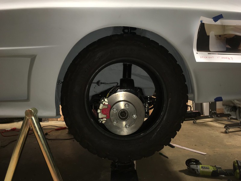
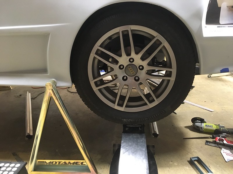
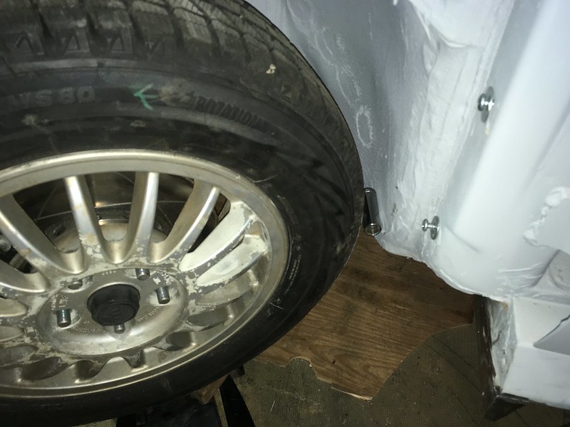
This week on "Will It Fit", we wanted to find out if a 215/65-15 BFG all-terrain tire would fit on a Quattro. Why? Because a customer wanted to know. Why? Because he put big-**** brakes on his quattro but now wants to go play in the dirt! We thought we could help especially as we had the exact same tire on our Allroad. Unfortunately we didn’t have any 16” wheels we could mount it on but we improvised.

We were very curious because, you may remember, we had trouble fitting 275/40-17 Hosiers on the rear of ours. Not because of the width but because of the diameter which was only 25.7”. It seems the rear arches are very small so unless the chosen tire stays inside them they will impinge on the lip when travelling upwards. The BFG is 27”OD!
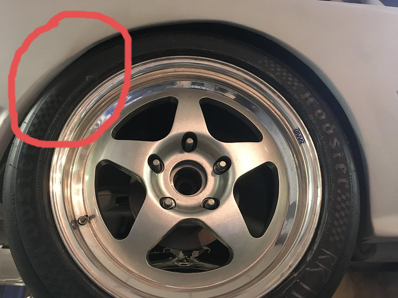
We’ve also seen that 205/65-15 rally tires (25”) will rub the underside of the spring perches but, fortunately, this customer’s car is already on coilovers.
So, by balancing a tire on the jack we were able to determine that the BFG tire would just fit inside the arch lip and go up inside the wheel house, if the offset were selected appropriately. ~ET22
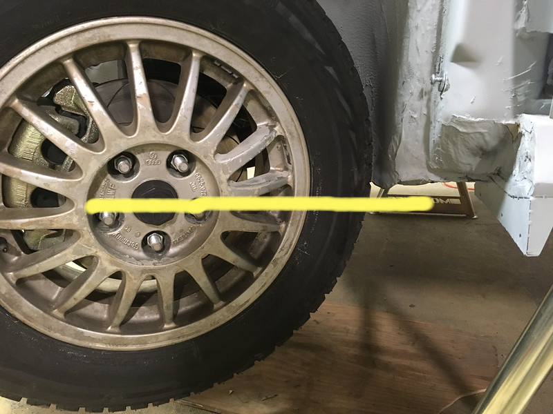
Then we remembered that our coffee table consists of four 225/55-17 (26.7”) tires on ET35 Allroad wheels and a glass top so we threw one of those on and it fit.
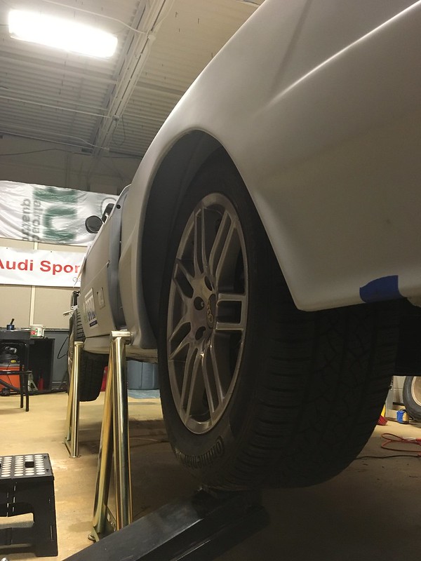
Then we tried it on the front:

Unfortunately this proved even tighter than the rear, for a couple of reasons. Firstly, it rubbed on the tie rod ball joint.

and front and rear inner fenders at full lock and full compression. Rears first.
The ball joint is not a problem as this tire is 10mm wider than the AT tires being considered but it is also 8mm smaller diameter which means clearing the inner fenders is going to be impossible without hitting them with a BFH!
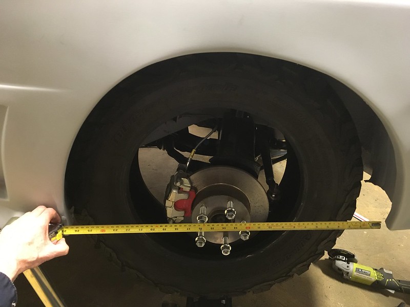
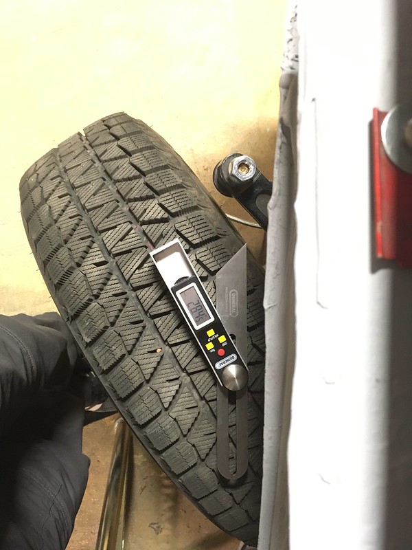
So what will fit? Turns out about 26.6” based on our jiggery-pokery.
Yes, that’s a 25” 195/65-15 tire with a socket being used as a feeler gauge! Not very big but do bear in mind the OE tires were only 23.5” OD. Still, all is not lost. Yokohama make their excellent Geolander A/T G015 in 215/60-16 and it is “only” 26.1” OD. So this tire might be an option.
https://ytc-bm.s3.us-east-2.amazonaws.com/GEOLANDAR-A-T-G015-LT-3QL-Web.png?mtime=20201218225019&focal=none[/img]
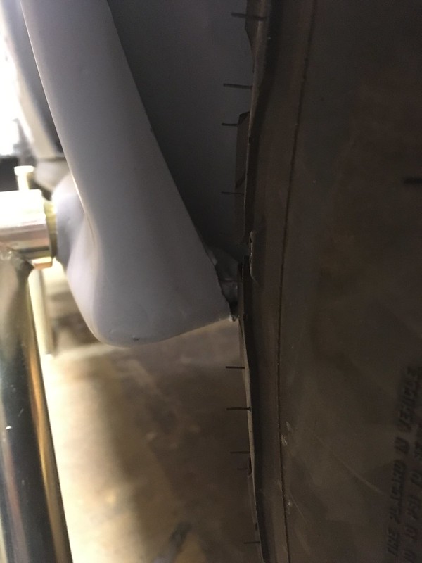
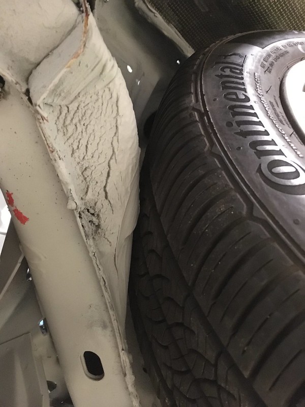
Still hopeful we could squeeze in the 215/65-16 we got creative. We investigated whether lifting the car would help. It is on coilovers after all. This is the 25” tire at full droop and, as you can see the center is about level with the bottom of the wheel house; the bit that rubs. So, unless you lift the car to the point that this is at full compression instead we don’t think a 27” tire will work.
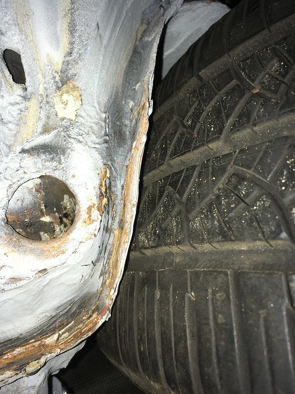
Then we investigated if restricting the steering angle would help. With the small tire on we determined that full lock is about 28 degrees. Then, with the big tire on we found it doesn’t start to rub until about 22 degrees.
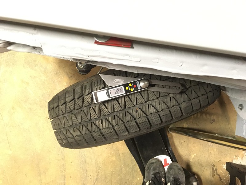
We are not sure if giving up 6 degrees of lock is a lot or how to restrict the rack but it might be a way forward. Alas, that is for someone else to figure out. We have a rally car to finish.

We were very curious because, you may remember, we had trouble fitting 275/40-17 Hosiers on the rear of ours. Not because of the width but because of the diameter which was only 25.7”. It seems the rear arches are very small so unless the chosen tire stays inside them they will impinge on the lip when travelling upwards. The BFG is 27”OD!
We’ve also seen that 205/65-15 rally tires (25”) will rub the underside of the spring perches but, fortunately, this customer’s car is already on coilovers.
So, by balancing a tire on the jack we were able to determine that the BFG tire would just fit inside the arch lip and go up inside the wheel house, if the offset were selected appropriately. ~ET22
Then we remembered that our coffee table consists of four 225/55-17 (26.7”) tires on ET35 Allroad wheels and a glass top so we threw one of those on and it fit.
Then we tried it on the front:
Unfortunately this proved even tighter than the rear, for a couple of reasons. Firstly, it rubbed on the tie rod ball joint.
and front and rear inner fenders at full lock and full compression. Rears first.
The ball joint is not a problem as this tire is 10mm wider than the AT tires being considered but it is also 8mm smaller diameter which means clearing the inner fenders is going to be impossible without hitting them with a BFH!
So what will fit? Turns out about 26.6” based on our jiggery-pokery.
Yes, that’s a 25” 195/65-15 tire with a socket being used as a feeler gauge! Not very big but do bear in mind the OE tires were only 23.5” OD. Still, all is not lost. Yokohama make their excellent Geolander A/T G015 in 215/60-16 and it is “only” 26.1” OD. So this tire might be an option.
https://ytc-bm.s3.us-east-2.amazonaws.com/GEOLANDAR-A-T-G015-LT-3QL-Web.png?mtime=20201218225019&focal=none[/img]
Still hopeful we could squeeze in the 215/65-16 we got creative. We investigated whether lifting the car would help. It is on coilovers after all. This is the 25” tire at full droop and, as you can see the center is about level with the bottom of the wheel house; the bit that rubs. So, unless you lift the car to the point that this is at full compression instead we don’t think a 27” tire will work.
Then we investigated if restricting the steering angle would help. With the small tire on we determined that full lock is about 28 degrees. Then, with the big tire on we found it doesn’t start to rub until about 22 degrees.
We are not sure if giving up 6 degrees of lock is a lot or how to restrict the rack but it might be a way forward. Alas, that is for someone else to figure out. We have a rally car to finish.
08-19-2021, 05:52 AM
#4
AudiWorld Member
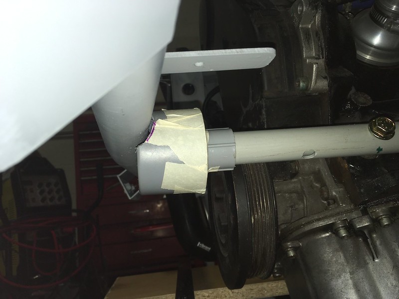
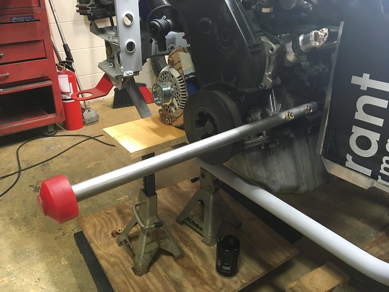
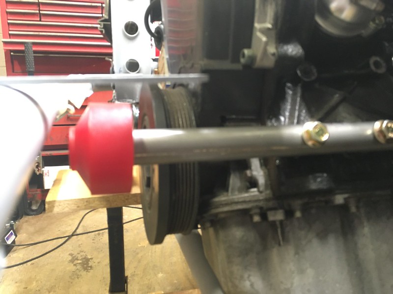
What’s this called? The Audi parts diagrams call it a “stop buffer” but what does it stop? Engine pitch perhaps? Well, it’s probably important so we should have one, exactly like the works cars of course. Oh boy! We’ll call it an Engine Pitch Stop or EPS.

It sits in a receptacle on the bumper bar and presumably stops the engine from pitching back and forth. Subarus have one on the bulkhead. We bought a performance one from ECS because who doesn’t want a big red *** sticking out of the front of their engine, even if it is mounted on a piece of PVC conduit!

We did intend to mount ours on the right side of the engine like the factory cars and even designed a mounting plate for it but then we realized it might be a bit complicated to design an alternator bracket in combination with this so decided to put it on the left side instead. It helped that there were two threaded holes in exactly the right place.
The EPS fits in a cup welded to the bumper bar so we needed to mock that up. Fortunately, we discovered that most paint can lids are the right size so a can of Rustoleum Self Etching Primer donated its lid. This intersects with the bumper bar about half way so we had to shape it carefully with a file.

It also changed color during the process because of, well, fail. Undaunted we acquired some steel tubes in the appropriate diameters and proceeded to recreate our plastic EPS in metal. First attempt was a little long.
That’s much better.
Now for the tricky bit.

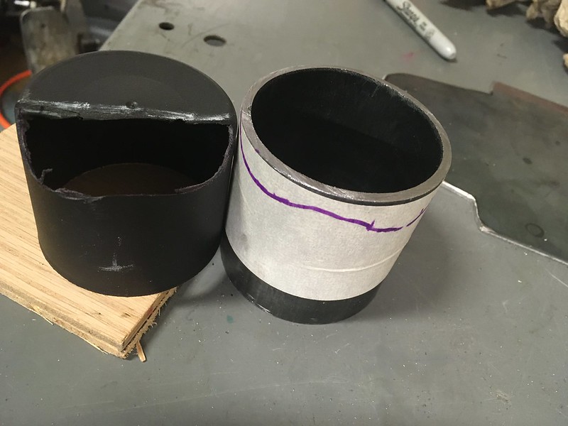

After about four days of filing, we had a fit. The cup fit on the bumper bar too.


Happy with the way it looked we cut it to length, welded it up, added a brace and stood back and admired it.

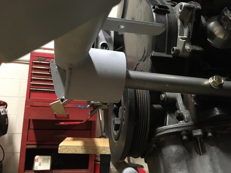
Can’t wait till its gold zinc plated.
It sits in a receptacle on the bumper bar and presumably stops the engine from pitching back and forth. Subarus have one on the bulkhead. We bought a performance one from ECS because who doesn’t want a big red *** sticking out of the front of their engine, even if it is mounted on a piece of PVC conduit!
We did intend to mount ours on the right side of the engine like the factory cars and even designed a mounting plate for it but then we realized it might be a bit complicated to design an alternator bracket in combination with this so decided to put it on the left side instead. It helped that there were two threaded holes in exactly the right place.
The EPS fits in a cup welded to the bumper bar so we needed to mock that up. Fortunately, we discovered that most paint can lids are the right size so a can of Rustoleum Self Etching Primer donated its lid. This intersects with the bumper bar about half way so we had to shape it carefully with a file.
It also changed color during the process because of, well, fail. Undaunted we acquired some steel tubes in the appropriate diameters and proceeded to recreate our plastic EPS in metal. First attempt was a little long.
That’s much better.
Now for the tricky bit.
After about four days of filing, we had a fit. The cup fit on the bumper bar too.
Happy with the way it looked we cut it to length, welded it up, added a brace and stood back and admired it.
Can’t wait till its gold zinc plated.
12-08-2021, 05:47 AM
#5
AudiWorld Member
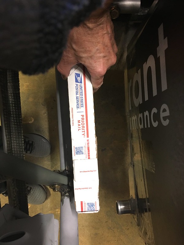
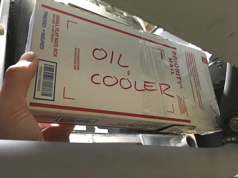
The Quattro rally cars all had a very iconic and loooong oil cooler tucked under their large, trunk mounted rear spoiler but we never wanted or needed the expensive dry sump oil system that goes with it so we are going to use a more traditional, front mounted oil cooler on this build. The stock oil cooler that came with our AAN engine is quite small, some would even say tiny, so we didn’t want to use that either.
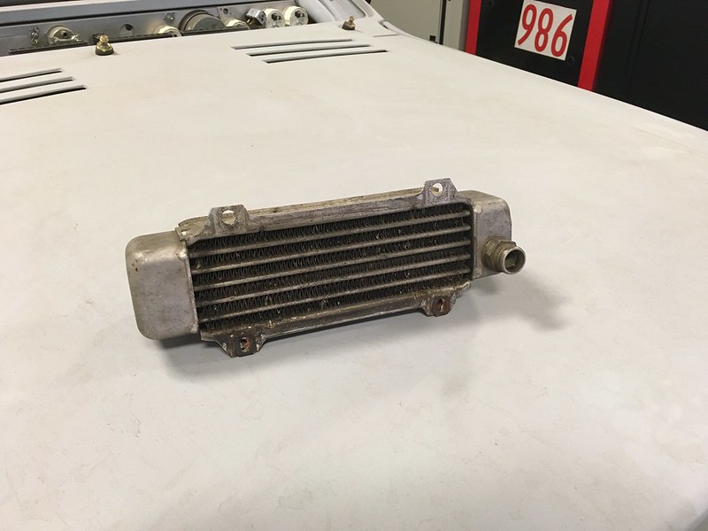
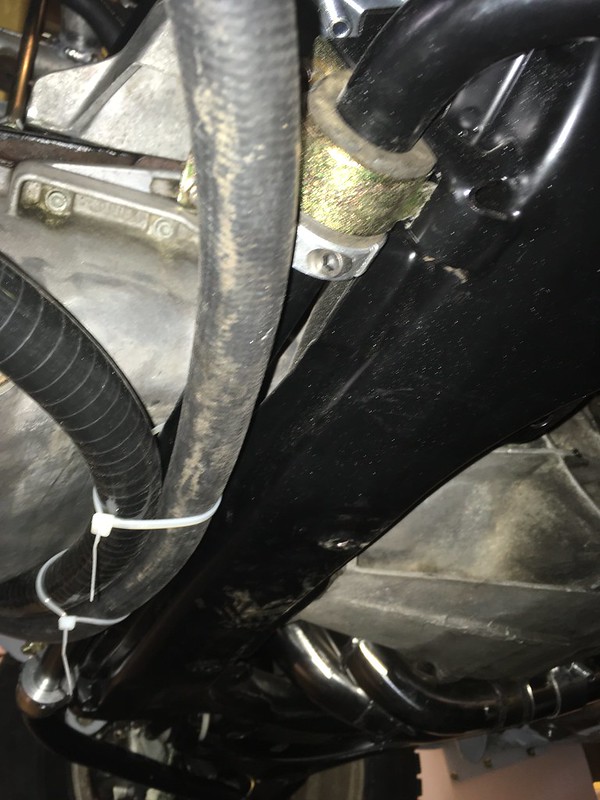
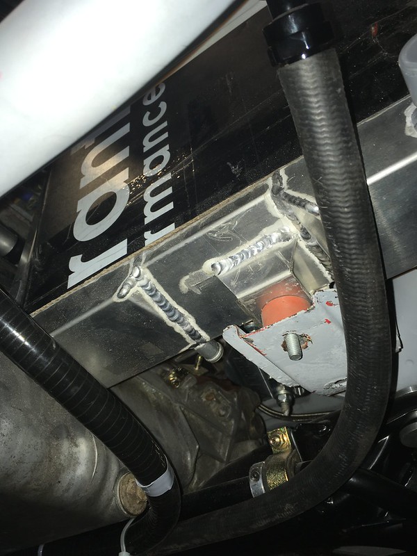
So we had always assumed we would use something from the aftermarket but what to use and, more importantly, where to put it? We looked for some free space that would be visited by cool air and also be accessible by some oil lines. The oil system and consequently the oil cooler inlet and outlet, are on the right side of the AAN engine but there was no room there now we had relocated the alternator and added the bars for the skid plate. It seemed the only place for it would be in front of the radiator on the left side of the engine. Lots of room there but no obvious route for the lines was present. We couldn’t go round the front of the engine as that’s already full of alternators, bumper bars, intercoolers and other stuff and round the back of the engine is full of pipes, wires and steering arms. After mocking up the skid plate in cardboard (see previous blog) we thought there was possibly room to squeeze two braided stainless steel oil lines under the engine between the back of the oil pan and the front sub frame and anti-roll bar then squeeze them under the radiator to the oil cooler if, and only if, we mounted the oil cooler with the connections underneath AKA upside down.


We were skeptical of this because we were concerned that the oil would drain out once the engine was turned off and, if still hot when started again, would cause a small delay in flowing oil to the engine as it would have to fill the oil cooler first. We are not sure if this is a genuine concern but didn’t want to find out the hard way. After a short session with a tape measure, we determined that most of our oil cooler would be below the oil cooler inlet and outlet on the block and therefore oil would not drain out YAY!
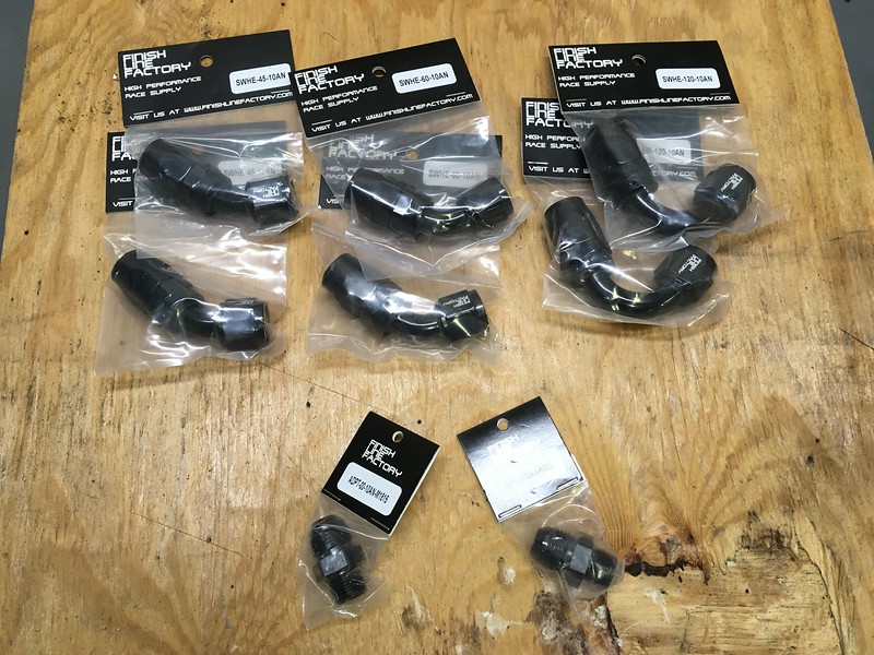
So, we started mocking it all up. Cardboard was required of course. We selected a cooler from Mishimoto but built a CAD model before placing the order; you know, just in case. We also ran some stainless-steel hoses under the oil pan to test that our intended route was indeed feasible. It was. So, we broke open the piggy bank and ordered some parts. AN fittings from Finish Line Factory, said Mishimoto oil cooler and some stainless steel lines.


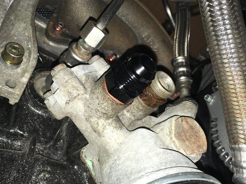
We were happy to be able to easily remove the OE fittings from the block and replaced them with AN adapters. We thought they might fight us but it seemed that they wanted out of there...
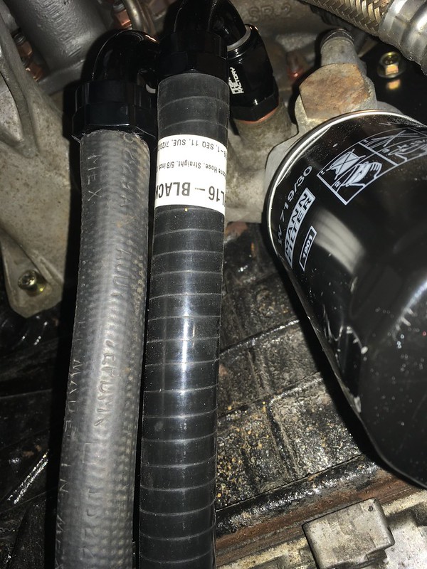
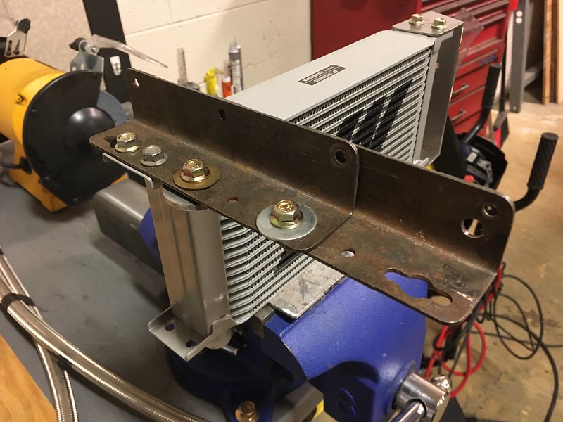
Then we set about mounting the (WISHIMOTO?) oil cooler. We fabbed up a bracket for the left side that bolts to the frame rail (currently with self-tappers but ultimately with rivnuts and screws of course.) For the right side we mocked up some steel angle we had lying around and attached that to the intercooler mount on the bumper bar as they were coincidentally at the same height. We’ll make a nicer aluminium version during final assembly.


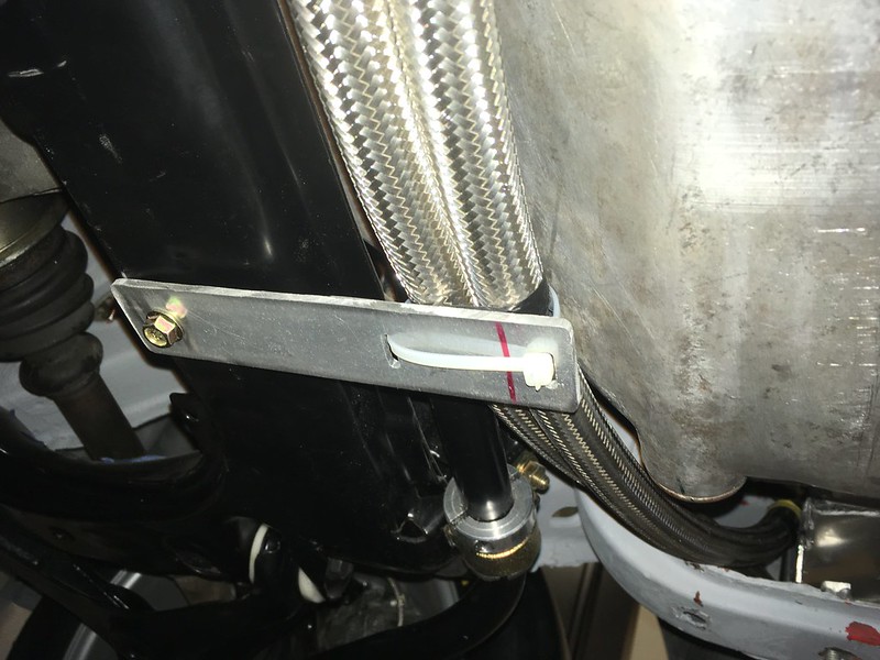
We’d order some 60* and 45* AN fittings from Finish Line Factory so could figure out which ones would line up best with the oil lines. We mocked all this up than realized we should secure the lines somehow as it didn’t seem like a good idea to have them sawing their way through the skid plate or worse, the oil pan. This bracket and (of course) a rally zip tie should do the trick.
So now, if we ever get this beast finished, we can be sure our engine oil will remain chill.
So we had always assumed we would use something from the aftermarket but what to use and, more importantly, where to put it? We looked for some free space that would be visited by cool air and also be accessible by some oil lines. The oil system and consequently the oil cooler inlet and outlet, are on the right side of the AAN engine but there was no room there now we had relocated the alternator and added the bars for the skid plate. It seemed the only place for it would be in front of the radiator on the left side of the engine. Lots of room there but no obvious route for the lines was present. We couldn’t go round the front of the engine as that’s already full of alternators, bumper bars, intercoolers and other stuff and round the back of the engine is full of pipes, wires and steering arms. After mocking up the skid plate in cardboard (see previous blog) we thought there was possibly room to squeeze two braided stainless steel oil lines under the engine between the back of the oil pan and the front sub frame and anti-roll bar then squeeze them under the radiator to the oil cooler if, and only if, we mounted the oil cooler with the connections underneath AKA upside down.
We were skeptical of this because we were concerned that the oil would drain out once the engine was turned off and, if still hot when started again, would cause a small delay in flowing oil to the engine as it would have to fill the oil cooler first. We are not sure if this is a genuine concern but didn’t want to find out the hard way. After a short session with a tape measure, we determined that most of our oil cooler would be below the oil cooler inlet and outlet on the block and therefore oil would not drain out YAY!
So, we started mocking it all up. Cardboard was required of course. We selected a cooler from Mishimoto but built a CAD model before placing the order; you know, just in case. We also ran some stainless-steel hoses under the oil pan to test that our intended route was indeed feasible. It was. So, we broke open the piggy bank and ordered some parts. AN fittings from Finish Line Factory, said Mishimoto oil cooler and some stainless steel lines.
We were happy to be able to easily remove the OE fittings from the block and replaced them with AN adapters. We thought they might fight us but it seemed that they wanted out of there...
Then we set about mounting the (WISHIMOTO?) oil cooler. We fabbed up a bracket for the left side that bolts to the frame rail (currently with self-tappers but ultimately with rivnuts and screws of course.) For the right side we mocked up some steel angle we had lying around and attached that to the intercooler mount on the bumper bar as they were coincidentally at the same height. We’ll make a nicer aluminium version during final assembly.
We’d order some 60* and 45* AN fittings from Finish Line Factory so could figure out which ones would line up best with the oil lines. We mocked all this up than realized we should secure the lines somehow as it didn’t seem like a good idea to have them sawing their way through the skid plate or worse, the oil pan. This bracket and (of course) a rally zip tie should do the trick.
So now, if we ever get this beast finished, we can be sure our engine oil will remain chill.
08-31-2023, 05:02 AM
#6
AudiWorld Member
PLAYING THE SLOTS
Building this car was always going to be a gamble but we had no idea how addictive it could be. And so, it was proven when we started to consider putting the screens into our bumper slots. We always thought they would need cleaning up a little but the closer we looked the worse they looked. We soon realized they were all the wrong shape and even, to some extent, in the wrong place! Oh boy; another rabbit hole. Here’s a comparison between ours (below) and a works car from back in the day.
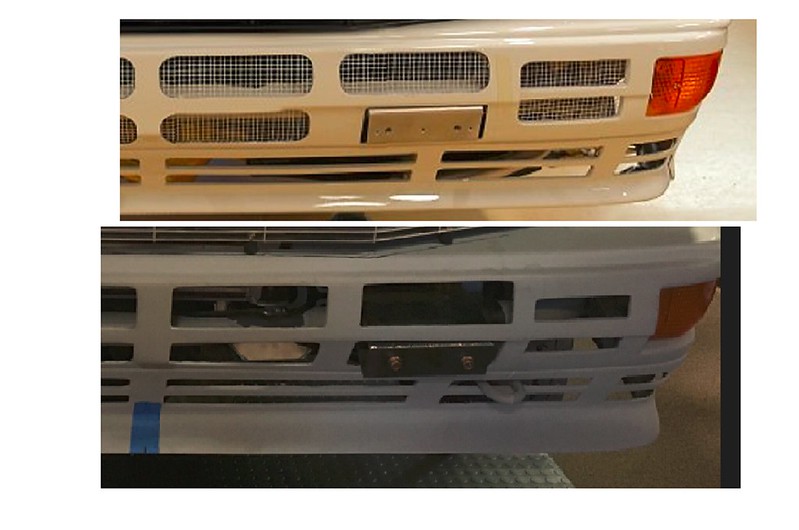

It might not be obvious but you can see how the large, upper slots are supposed to have fillets in the corners. They are also supposed to be equi-spaced and centered about the centerline of the bumper. Ours weren’t. Even though most these will be covered by giant spotlights we just couldn’t live with it so set about fixing them. We assumed we could live with the lower, thinner slots as they were however.
Using a suitable size socket, we estimated how much radii we needed in each corner and drew a template and a buck (right term?) to shape the slots around. We thought we’d need to use fiber-glass to add the needed material but as the fillets ended up being really small, we just used reinforced body filler instead. In fact, on many of the slots we were just removing material, they were that far off. So, after hours of filling and sanding over and over we finally had our big slots perfect-ish.


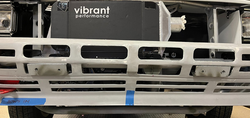
Unfortunately, we then looked at the smaller side slots. They were even further out.


Check back later to see if we managed to leave the lower slots alone. (spoiler alert: we didn’t)
Building this car was always going to be a gamble but we had no idea how addictive it could be. And so, it was proven when we started to consider putting the screens into our bumper slots. We always thought they would need cleaning up a little but the closer we looked the worse they looked. We soon realized they were all the wrong shape and even, to some extent, in the wrong place! Oh boy; another rabbit hole. Here’s a comparison between ours (below) and a works car from back in the day.
It might not be obvious but you can see how the large, upper slots are supposed to have fillets in the corners. They are also supposed to be equi-spaced and centered about the centerline of the bumper. Ours weren’t. Even though most these will be covered by giant spotlights we just couldn’t live with it so set about fixing them. We assumed we could live with the lower, thinner slots as they were however.
Using a suitable size socket, we estimated how much radii we needed in each corner and drew a template and a buck (right term?) to shape the slots around. We thought we’d need to use fiber-glass to add the needed material but as the fillets ended up being really small, we just used reinforced body filler instead. In fact, on many of the slots we were just removing material, they were that far off. So, after hours of filling and sanding over and over we finally had our big slots perfect-ish.
Unfortunately, we then looked at the smaller side slots. They were even further out.
Check back later to see if we managed to leave the lower slots alone. (spoiler alert: we didn’t)

Thread
Thread Starter
Forum
Replies
Last Post
bosmass
Quattro: Turbo / Ur / Sport
8
10-14-2018 09:35 PM
Jardine Motors Audi
Want To Buy - Archive (NO NEW POSTS HERE)
0
08-07-2015 12:41 AM
Jardine Motors Audi
Quattro: Turbo / Ur / Sport
4
07-09-2015 06:10 AM

