Timing Belt replacement writeup with 61 pictures and 44 steps....>>
 01-13-2009, 08:39 PM
#1
AudiWorld Super User
Thread Starter

I replaced the Timing Belt, Water Pump, Tensioning Roller, Tensioning Dampener, and Ribbed (accessory) Belt on my 2002 Audi TT 225 (AMU engine). This write-up is intended to serve as a reference only and no liability is assumed for use of any information contained within.
Tools recommended include:
Bentley Publishers Audi TT Service Manual (book or CD), Torque Wrench (3/8" drive recommended), Floor Jacks (2 minimum), Jack Stands (3 minimum), Tool Set including ratchet / extensions / wrenches / metric sockets (various lengths) / hex bit sockets / torx drivers / allen wrenches, Wheel Chocks (2), Small Clamps, and a digital camera to document your progress in case you need to go back and review how it was originally installed.
Supplies recommended include:
3 Liters of VW/Audi G-012 Coolant Antifreeze, 3 Liters of Distilled Water, 1/2-gallon Clear plastic pitcher (for mixing distilled water and Coolant), 1 Liter of VW/Audi G-004 Power Steering Fluid (a lot less is needed), Loctite high temperature Threadlocker, Bucket & Hose to drain coolant (hose ID approximately 10mm), Shop Towels/Rags, Plastic Bags (Ziploc), Zip Ties, Rubber Stoppers (to plug coolant and power steering hoses), Marking Pen (Red China Marker), and an Abrasive Pad (ScotchBrite).
A Dieselgeek Timing Belt replacement kit was purchased with all the necessary replacement parts. The kit included a new Timing Belt, Tensioning Roller, Ribbed Belt, Tensioning Dampener, Engine Mount Bolts, and Water Pump with metal impeller: http://www.dieselgeek.com/Audi_TT_GT...kit_s/1833.htm

Step 1: Preparation.
In preparation make sure the car is on a level surface with enough room to place a floor jack on both sides. Engage the Emergency Brake and Chock the rear wheels. Carefully raise the vehicle and place it on Jack Stands. DO NOT ATTEMPT this if you are unsure of how to safely lift the vehicle or properly place Jack Stands! The Bentley Service Manual includes information on Lifting Vehicle and Working under the Vehicle on pages 03-11 through 03-13.
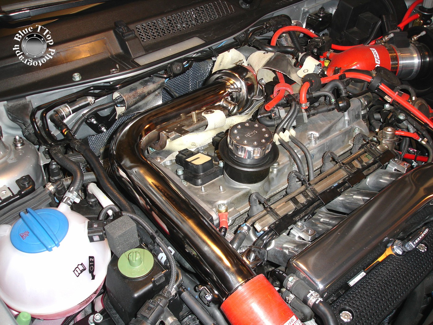
Step 2: Remove Engine Covers and Charge Pipe.
Remove the plastic covers over the engine and coolant reservoir. Bentley Manual page 03-15.
Then remove the Charge Pipe so you have easy access to the Timing Belt Cover and Engine Mount below it. Bentley Manual page 15a-12.
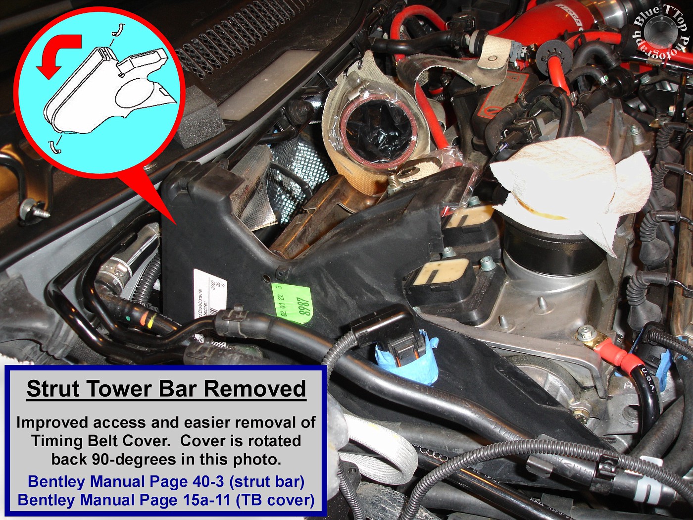
Step 3: Remove Strut Tower Bar (optional).
This is optional, but was found to improve access and made removal of the Timing Belt Cover much easier. Use a 13mm socket to remove Strut Tower Bar and right-side mounting bracket. Bentley Manual page 40-3.
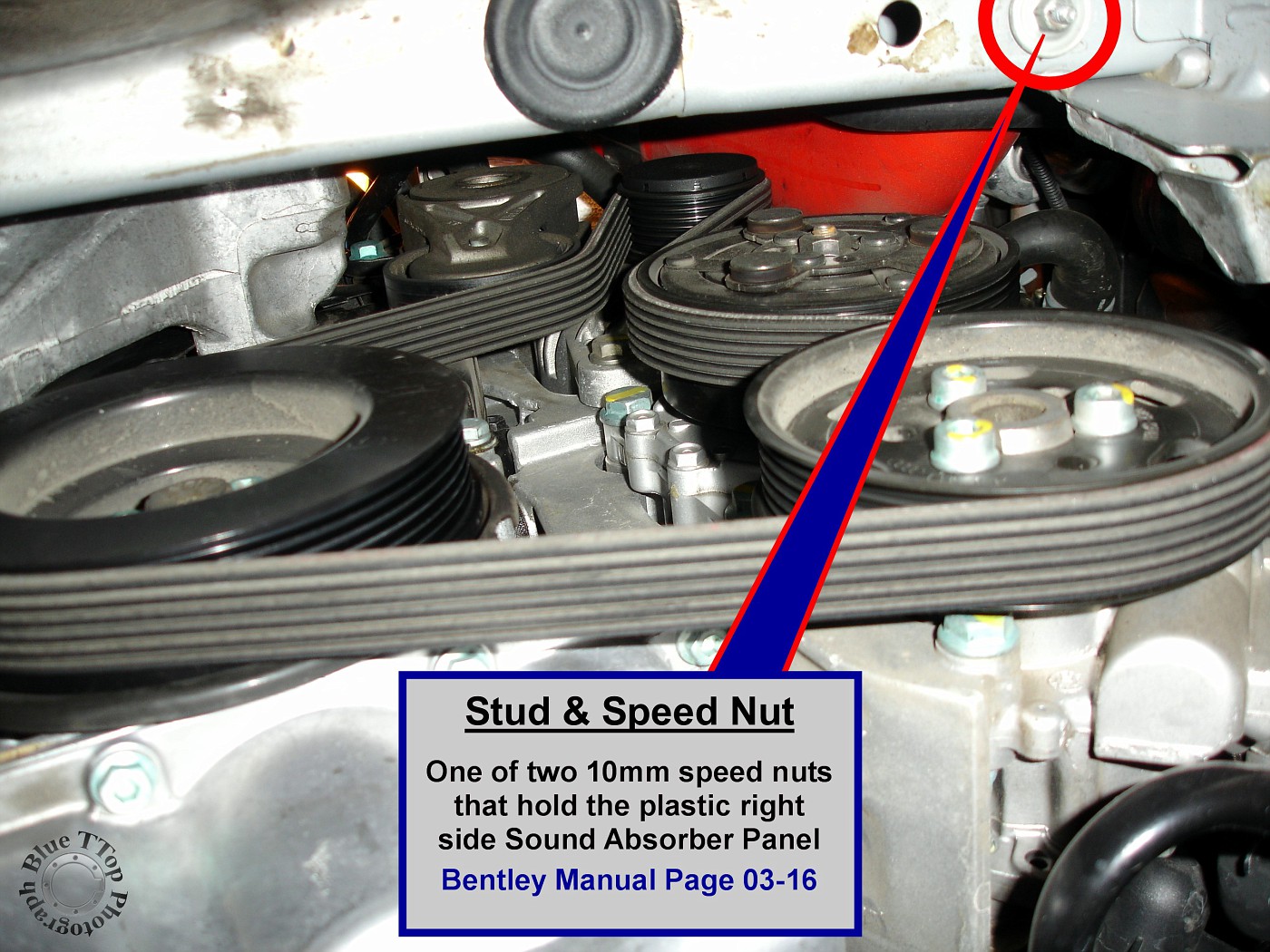
Step 4: Remove Wheel, Sound Absorber Panels, and Wheel-Arch Liner.
Remove the right front wheel. Remove the plastic Wheel-Arch Liner. Remove the plastic lower Sound Absorber Panel (under tray) and the plastic lower right-side Sound Absorber Panel. Bentley Manual page 03-16.

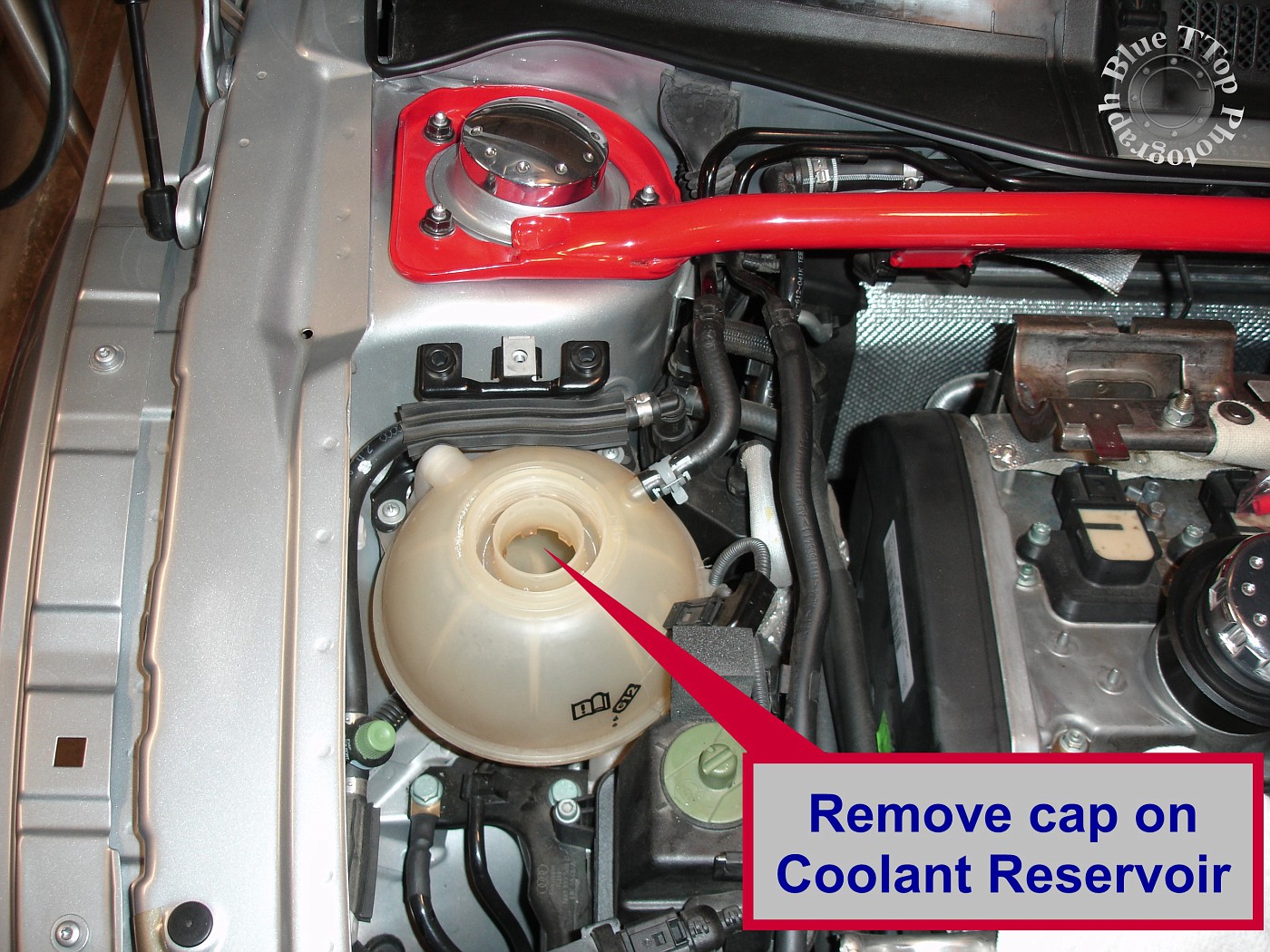
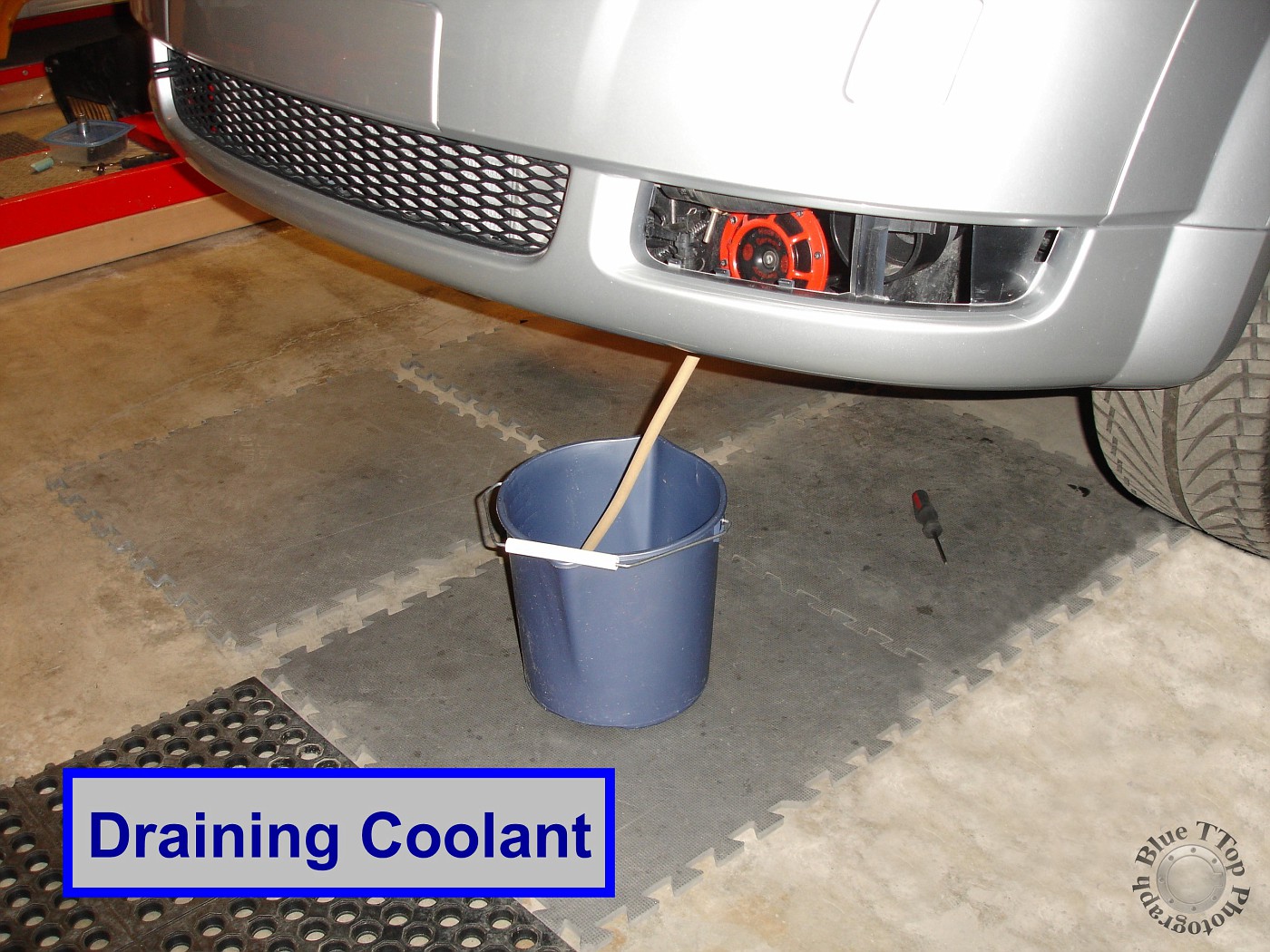
Step 5: Drain Coolant.
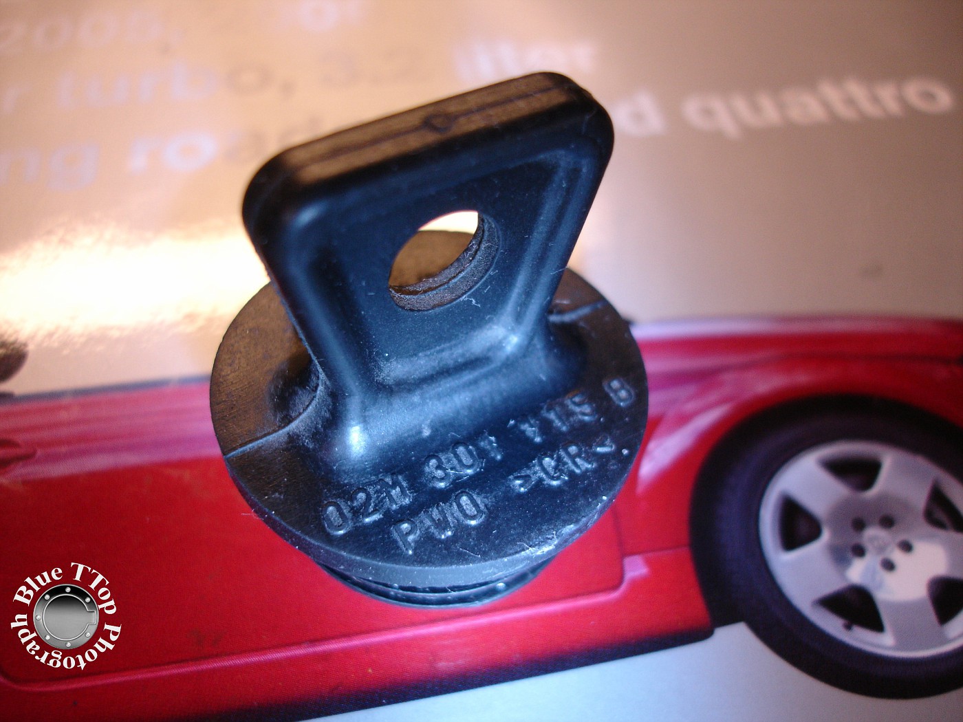
Remove cap from Coolant Reservoir. NOTE: Make sure the engine is cool! Place hose end in a bucket and attach the other end to the Coolant Drain Valve. Turn Valve **** counter clockwise and pull out to open and drain coolant. Bentley Manual page 19-5.
Step 6: Remove Coolant Reservoir.
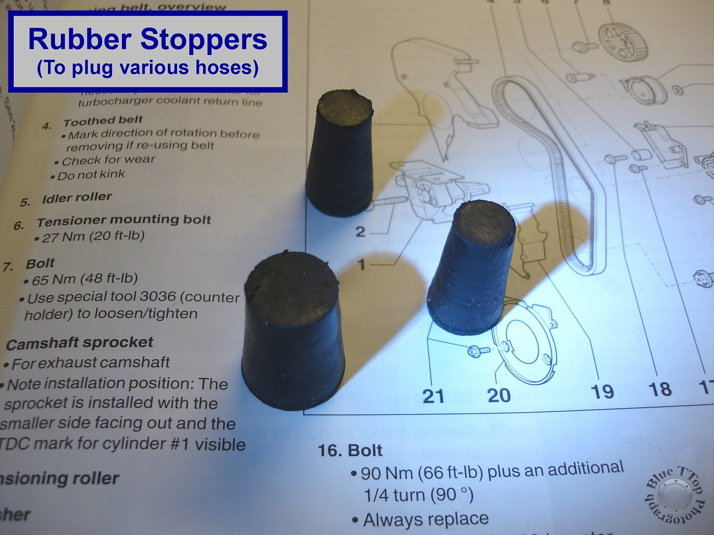
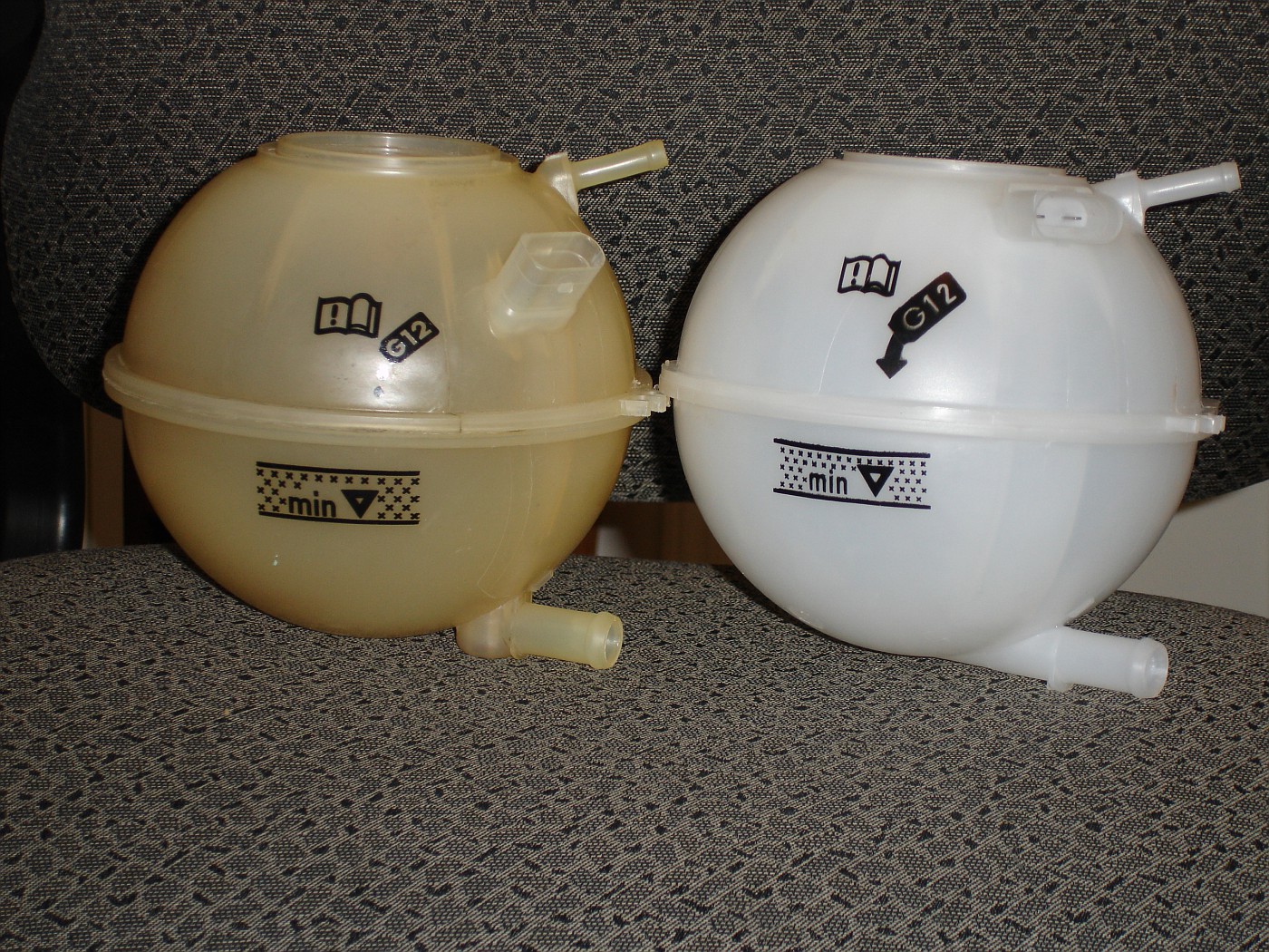
Disconnect and remove the Coolant Reservoir. The tank had yellowed over time and was also replaced. Disconnect the Wire Harness on top of the tank. Then remove the 2 Phillips-head screws. Bentley Manual page 19-9. Disconnect the hose visible on top of the tank first. Then lift the tank to expose and remove the lower hose connection. Insert rubber stoppers to prevent dripping.

Rubber stoppers in various sizes available at any hardware store.
Existing 6-year old tank on left compared to new tank.
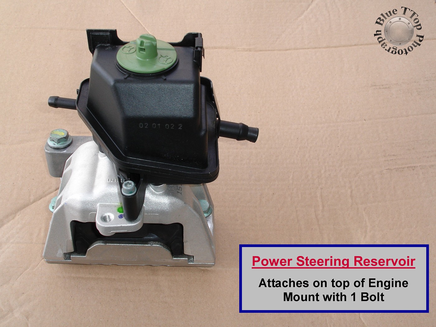
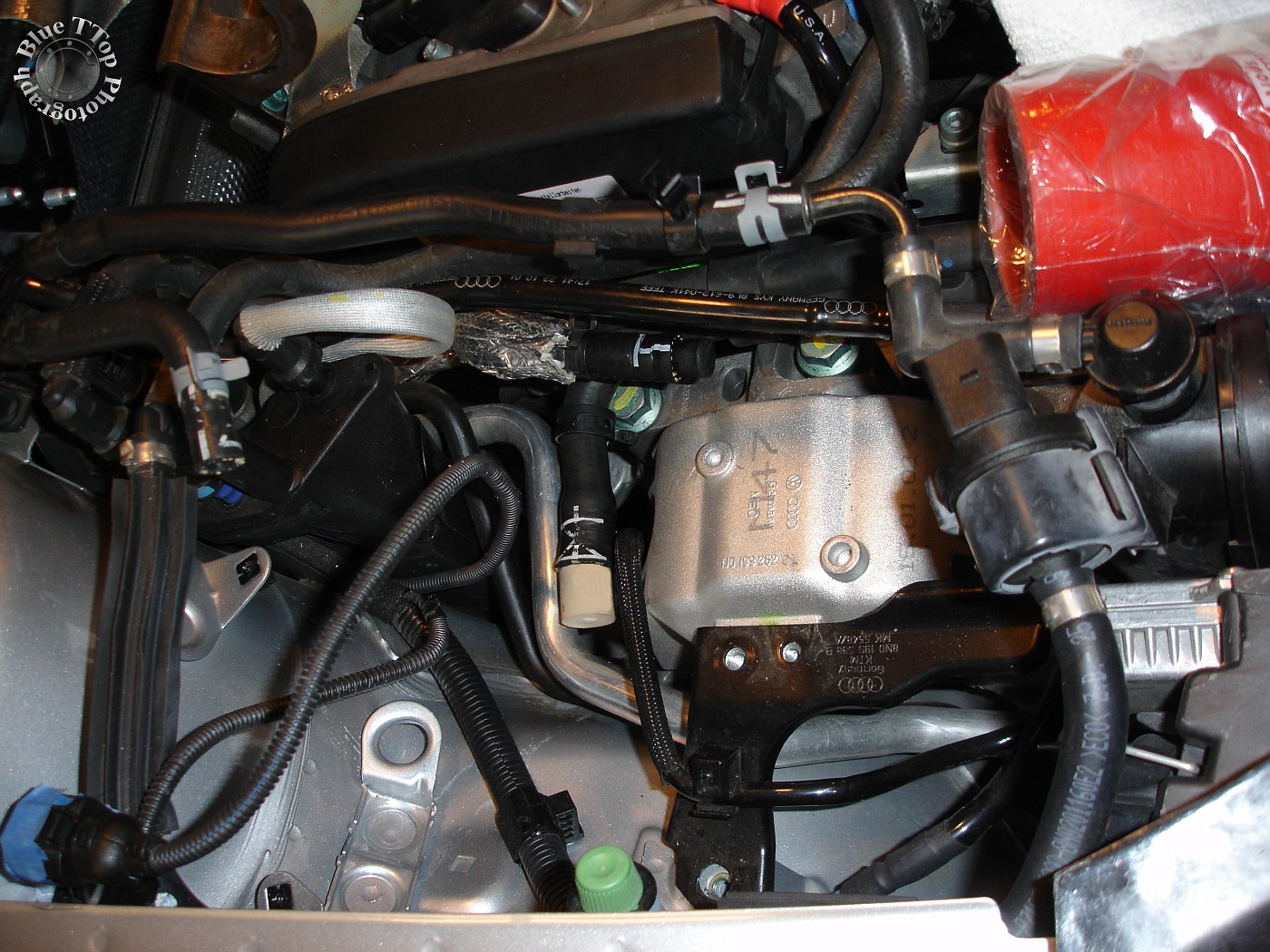
Step 7: Remove Power Steering fluid reservoir.
Power Steering reservoir is held in place by 1 - 5mm allen-head bolt and 2 hoses. The picture below shows how the reservoir sits on top of the Engine Mount. Bentley Manual page 03-31.
Remove the single bolt holding the reservoir. I then put some paper towels inside a Ziploc bag and positioned one under each hose connection. Disconnect the hose and let the fluid drain into the bag. Then insert a rubber stopper into each hose to prevent dripping.

With the Power Steering reservoir removed the Engine Mount is now completely exposed.
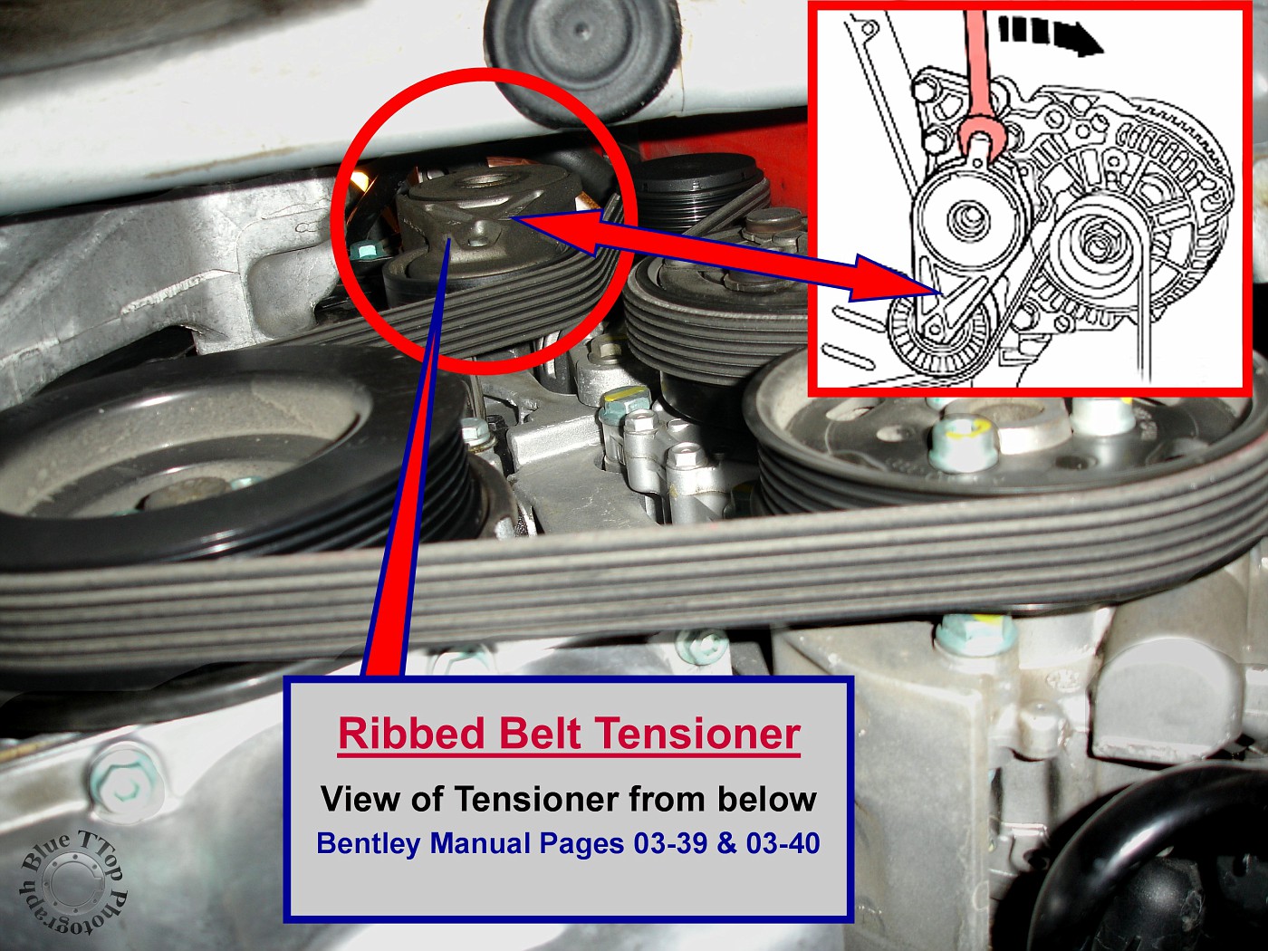
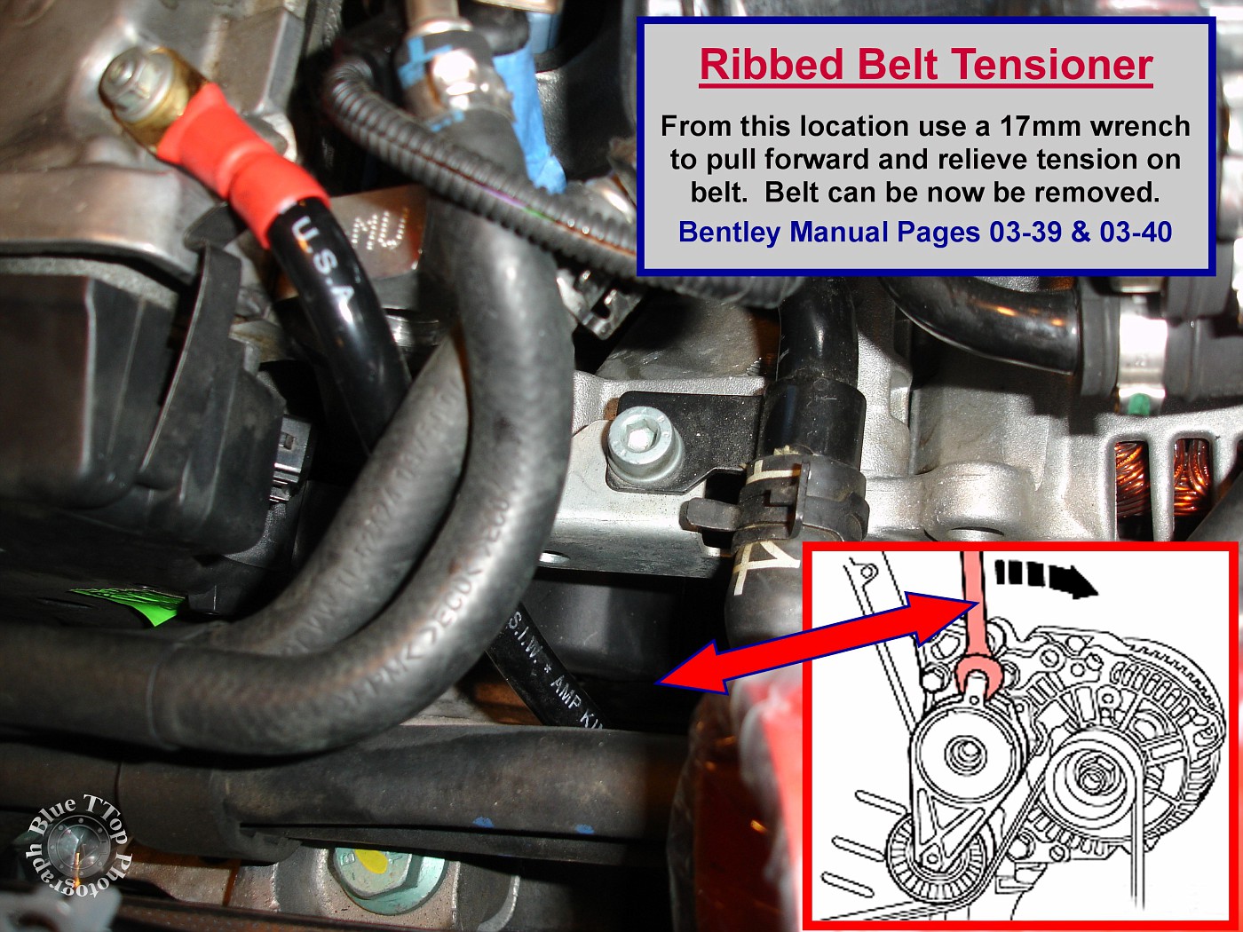
Step 8: Remove the Ribbed Belt and Tensioner.
Use a 15mm wrench on top of the Tensioner and pull forward towards front bumper. While pulling the wrench forward the tension on the ribbed belt will be relieved and the belt can be removed. Bentley Manual pages 03-39 and 03-40.
The Tensioner can be seen from underneath in this picture.
View of engine bay location where Tensioner can be accessed to release Ribbed Belt.
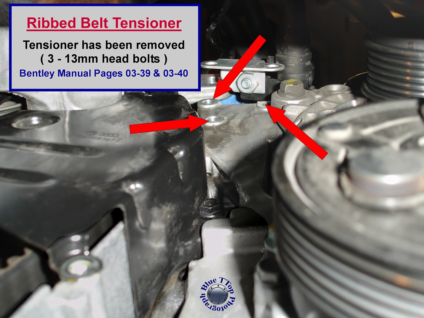
Once the Ribbed Belt is removed the Tensioner can be removed. It is held in place by 3 - 13mm head bolts. Remove the 3 bolts and remove the Tensioner. A bracket holding the Charge Pipe will also be removed. Tightening torque for these 3 bolts is listed as 18 ft-lb. NOTE: If Ribbed Belt is going to be reused, mark direction of the belt before removal.
Step 9: Remove Crank Pulley.
Remove Crank Pulley by removing 4 allen-head bolts. Tightening torque for these 4 bolts is listed as 18 ft-lb. Use a 19mm socket on Crank Gear to hold back on pulley to loosen bolts.
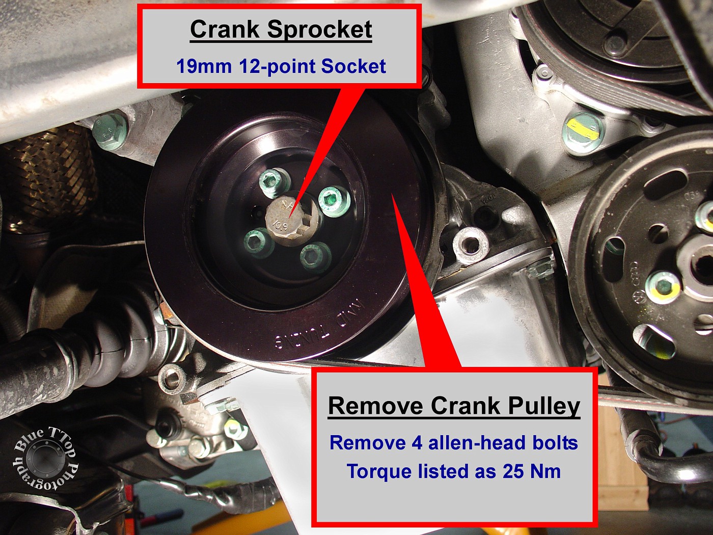
This picture shows Crank Pulley removed and lower timing belt cover exposed.

Step 10: Remove Upper Timing Belt Cover.
Unclip the top Timing Belt cover by releasing both clips (front and back). It will take some careful finagling, but with the Strut Tower Bar already removed it was much easier to remove and install.
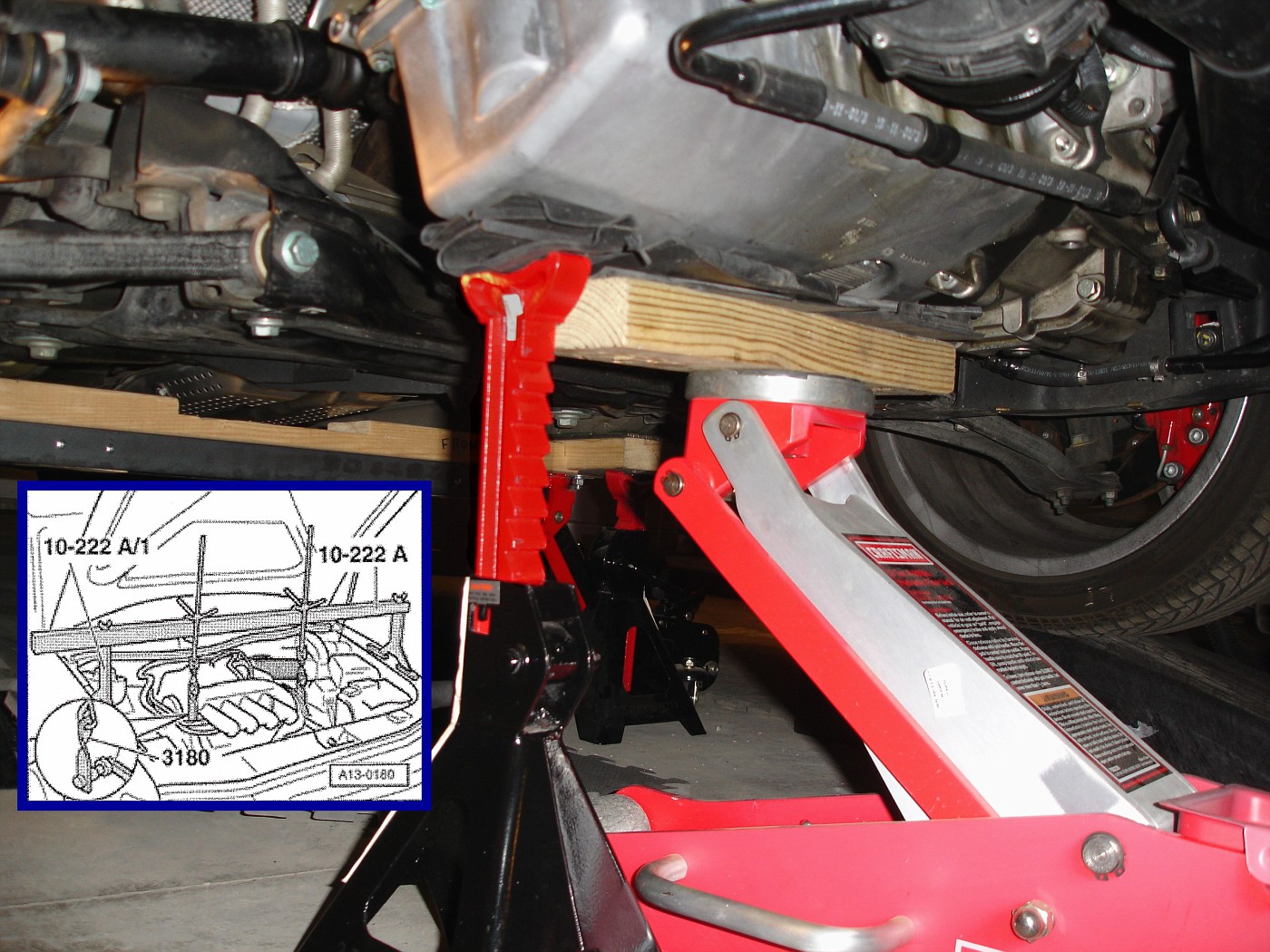
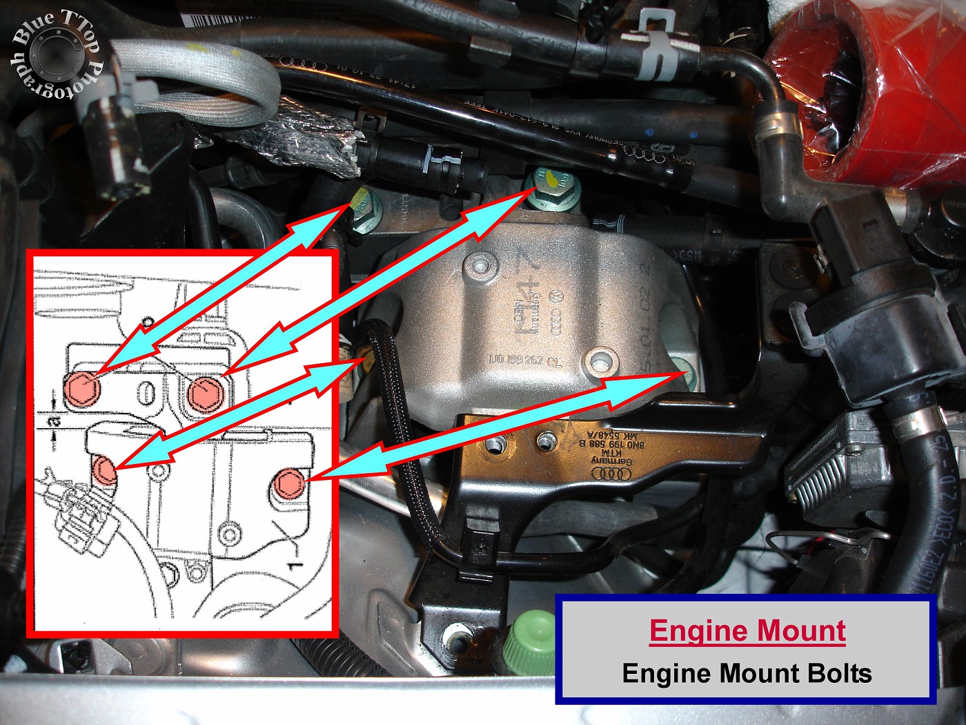
Step 11: Remove Engine Mount.
Proper support of the Engine is CRITICAL. This work should be done with an engine hoist or engine support bar designed for this purpose (see inset on photo below). Bentley Manual page 15a-13. Supporting the engine underneath with a jack and jack stand is dangerous and not recommended.
Start by removing the 2 bolts that hold a bracket on top of the Engine Mount. Then, with the engine properly supported, the 4 one-time-use stretch-bolts holding the Engine Mount can be removed. The 2 bolts nearest to the fender can be removed with a 16mm socket (Part # N-105-167-01). The 2 bolts closer to the engine can be removed with an 18mm socket (Part # N-102-096-03). NOTE: All 4 bolts must be replaced. Bentley Manual page 15a-16.
This photo shows the Engine Mount removed and the Engine Mount Bracket exposed.
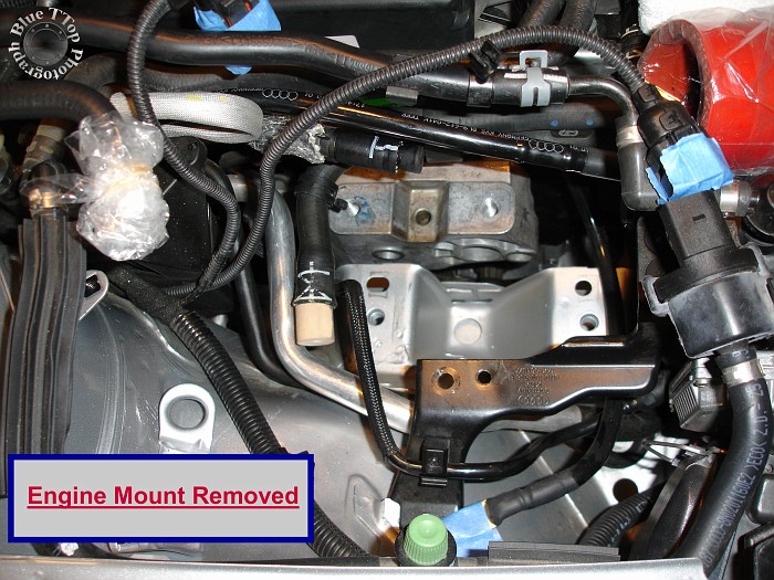
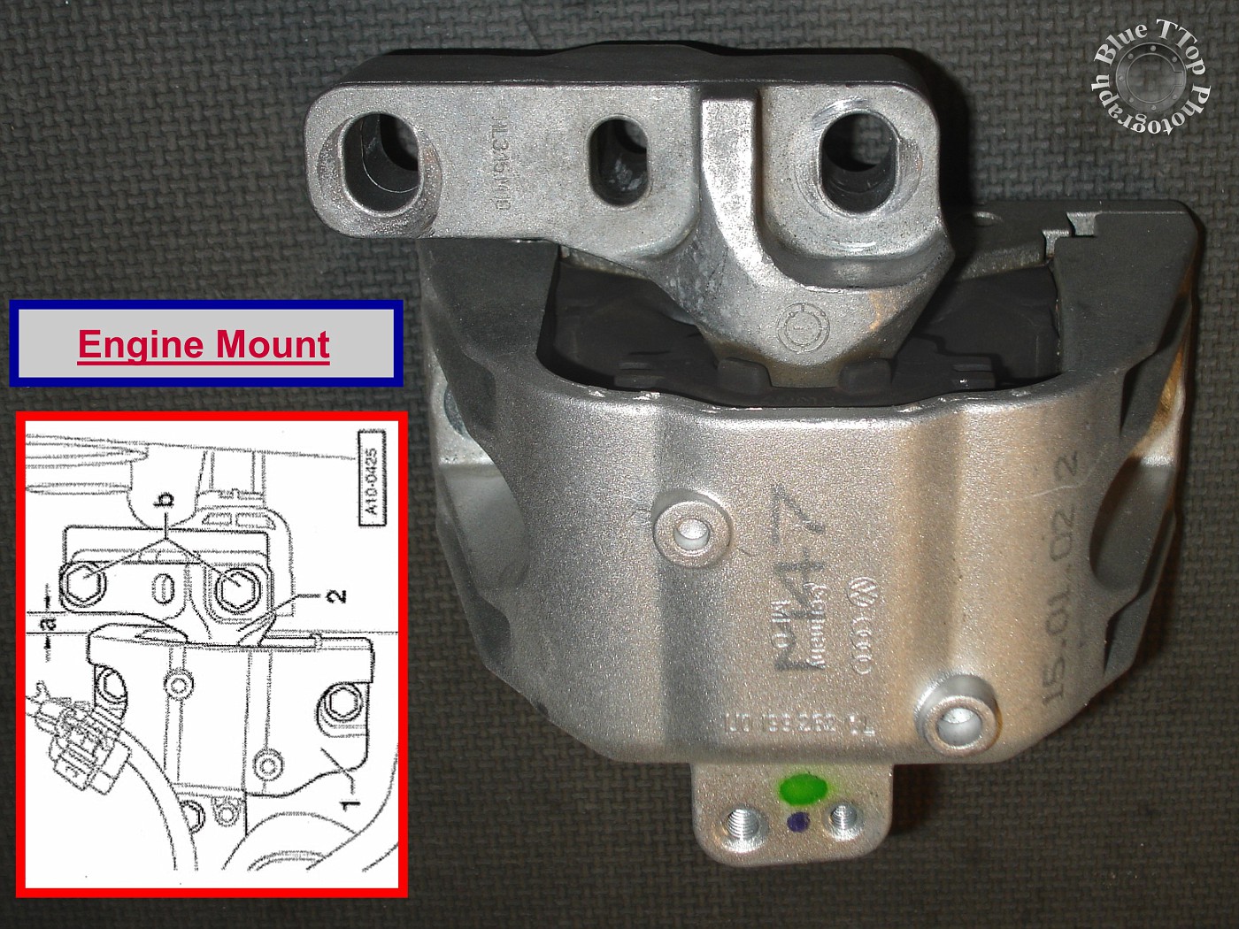
The Engine Mount removed from the vehicle.
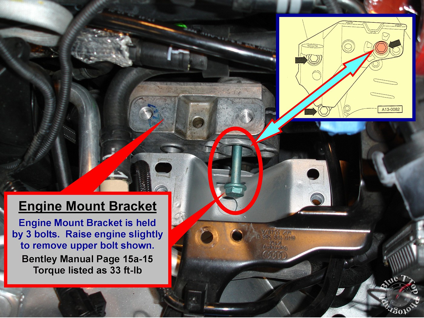
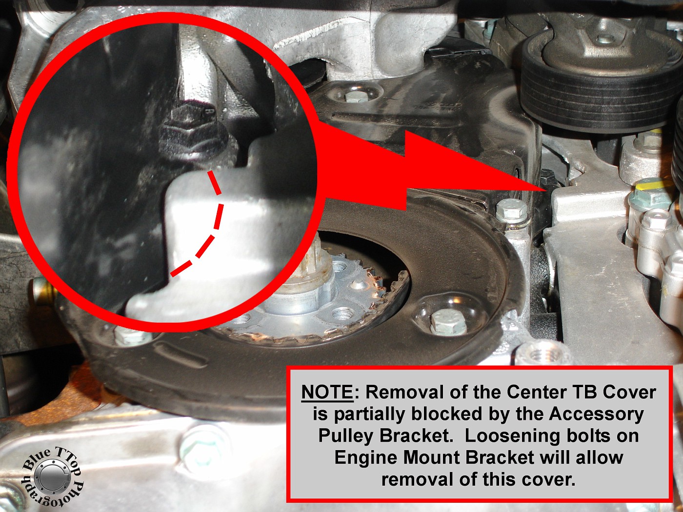
Step 12: Loosen Engine Mount Bracket.
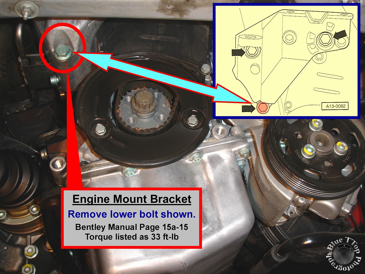
The Engine Mount Bracket is bolted to the side of the engine with 3 bolts. Remove the upper-front and lower-rear bolts. The upper-front bolt can be accessed from the engine bay. Raise the engine slightly until bolt can be removed as shown in photo. Bentley Manual page 15a-15.
Lower the engine slightly to remove the lower-rear bolt shown in photo. Then, using a deep socket, loosen the remaining bolt to allow the Engine Mount Bracket to pivot (will allow removal of the Middle Timing Belt Cover).
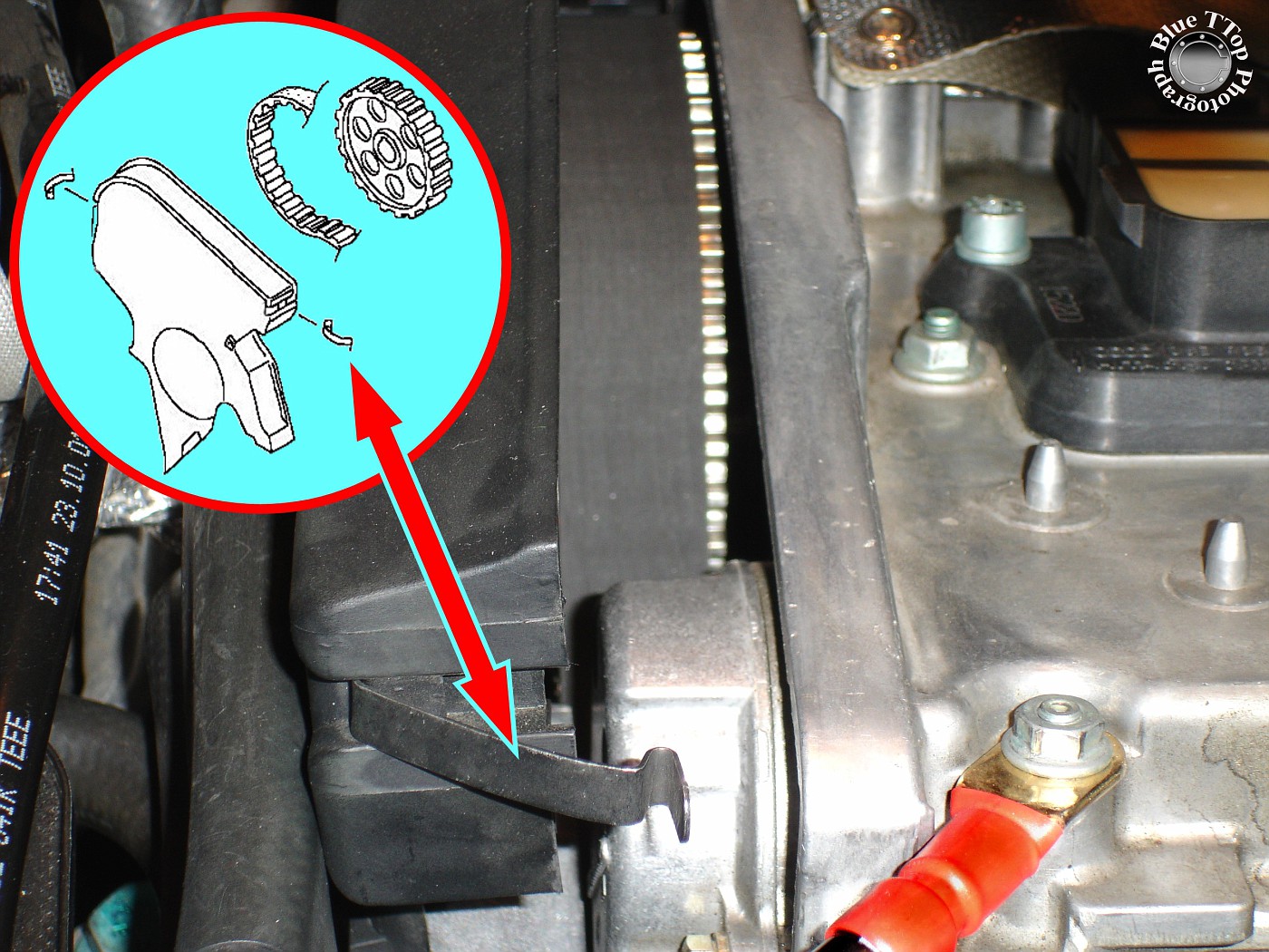
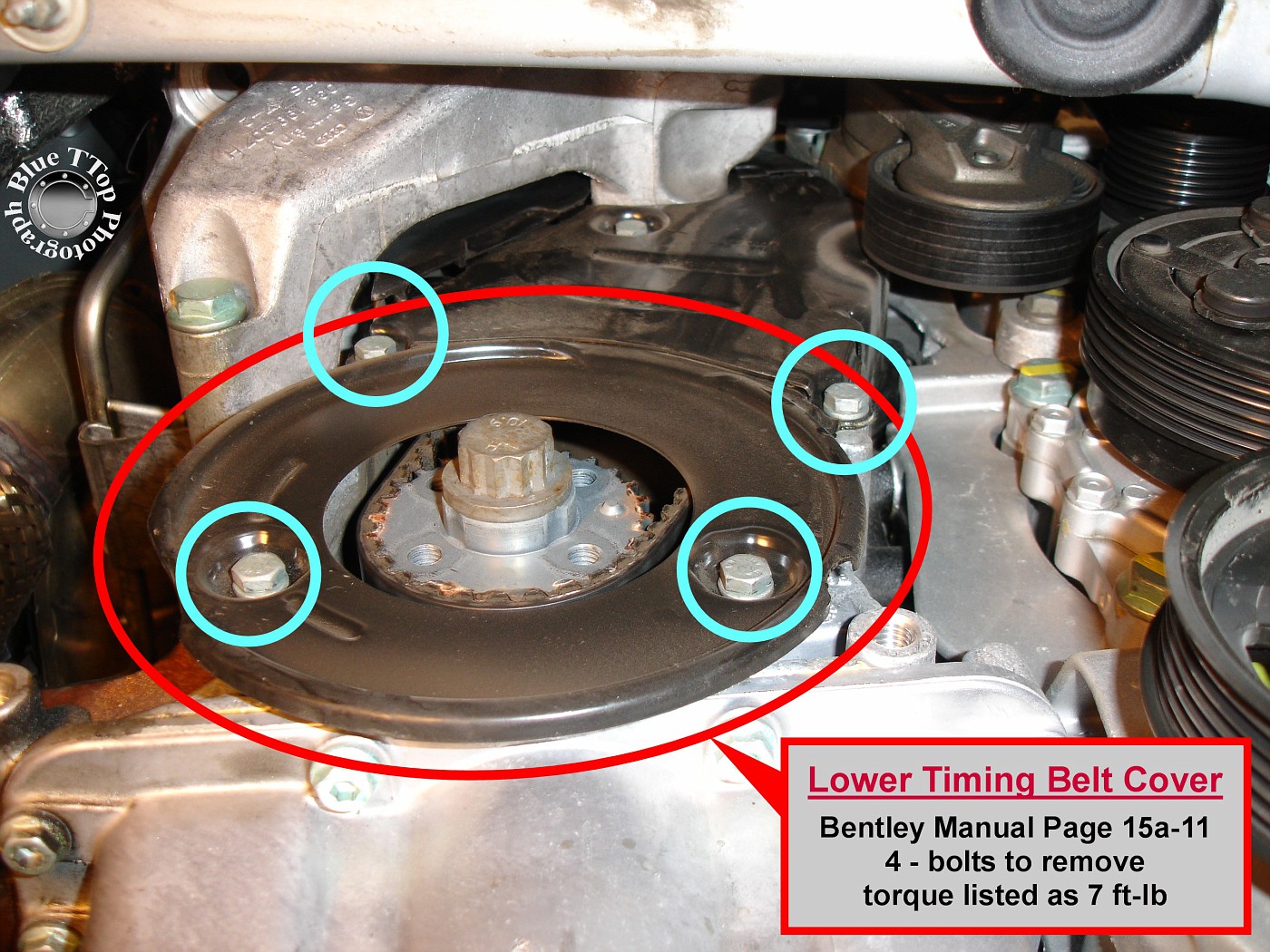
Step 13: Remove Lower Timing Belt Cover.
Lower Timing Belt Cover is held in place by 4 - 10mm hex-head bolts shown in photo. Tightening torque is listed as 7 ft-lb. Bentley Manual page 15a-11.
Step 14: Remove Middle Timing Belt Cover.
Middle Timing Belt Cover is held in place by 1 - 10mm hex-head bolt shown in photo below. Tightening torque is listed as 7 ft-lb. Bentley Manual page 15a-11.
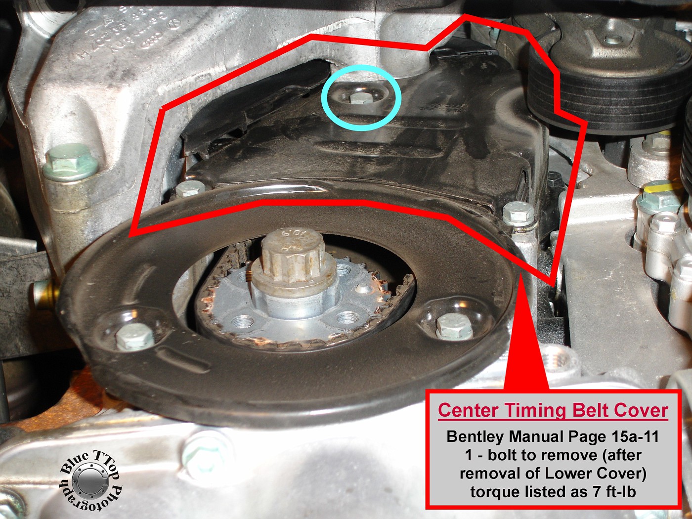
NOTE: Removal of Middle Timing Belt Cover is much easier if Engine Mount Bracket is already loose and able to pivot slightly.
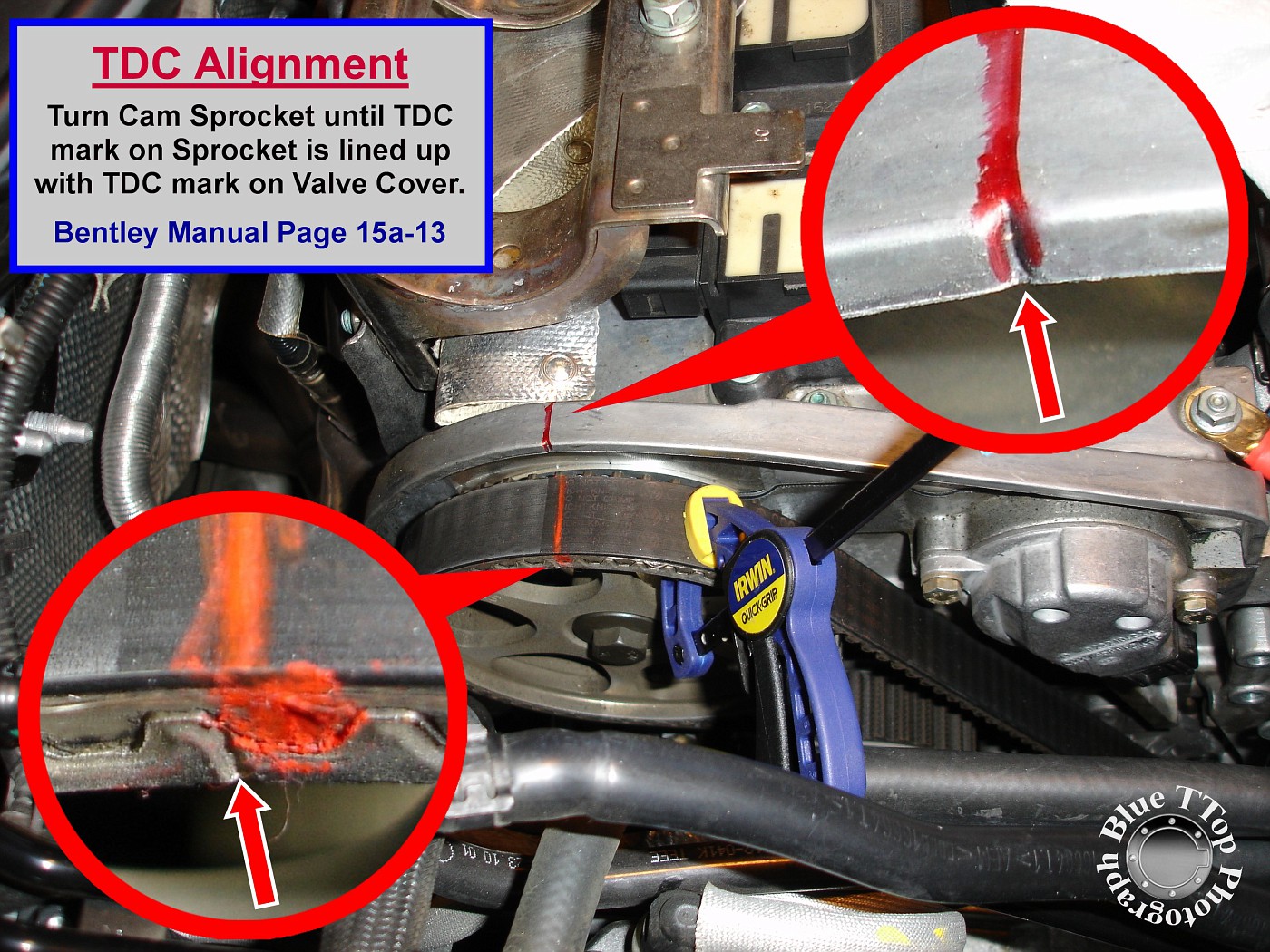
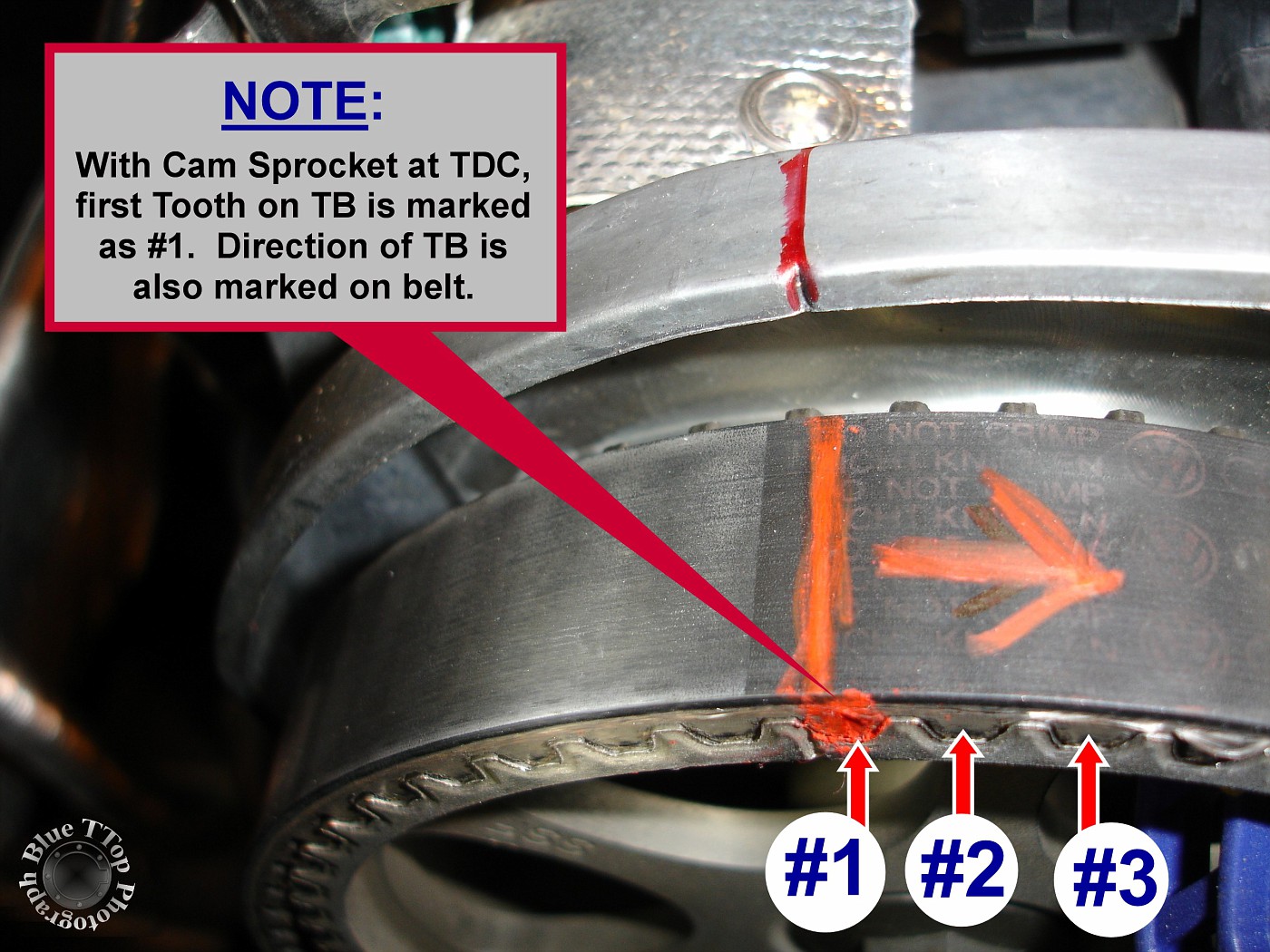
Step 15: Align Top Dead Center (TDC) marks on Cam Sprocket and Valve Cover.
Use a socket on the center bolt of the Cam Sprocket to rotate clockwise until TDC marks are aligned. Then clamp the Timing Belt to the Cam Sprocket to eliminate slippage later on. Bentley Manual page 15a-13.
Mark the Timing Belt at the location where the TDC notch on the Cam Sprocket lines up with the TDC notch on the Valve Cover. Mark the direction of the belt with an arrow (clockwise). Note: Use a marker that will not easily rub or wash off.
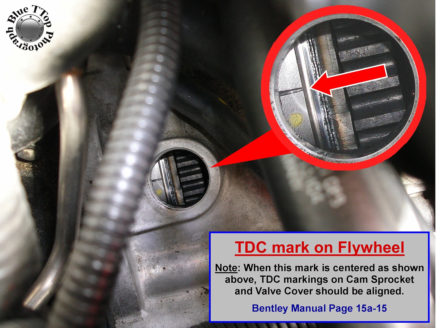
Step 16: Confirm TDC mark on Flywheel.
Remove rubber cap on Transmission to view TDC mark on Flywheel.
If TDC is aligned on Cam Sprocket and Valve Cover, then TDC notch on Flywheel should be visible as shown in this photo. Note: Do NOT remove Timing Belt until TDC confirmed at both the Cam Sprocket and the Flywheel. Bentley Manual page 15a-15.
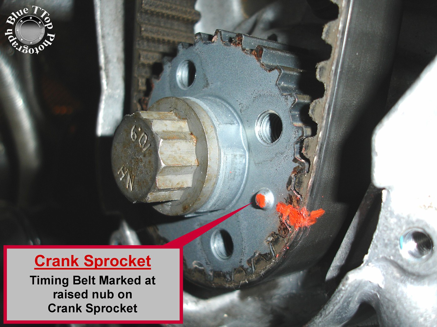
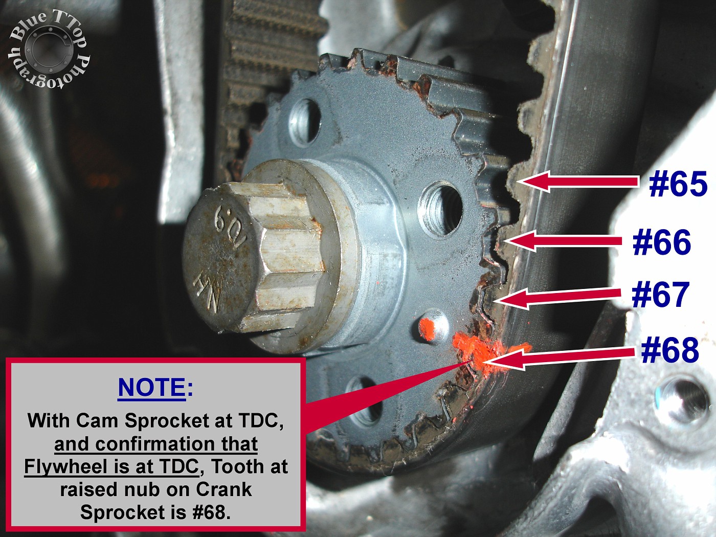
Step 17: Mark Timing Belt at Crank Sprocket.
Once TDC is confirmed at Cam Sprocket and Flywheel it is time to mark the Timing Belt at the Crank Sprocket. Mark the raised nub on the Crank Sprocket and the adjacent Timing Belt tooth. NOTE: Markings on the Timing Belt need to be clear and NOT easily removed. These marks will need to be transferred to the new Timing Belt prior to installation.
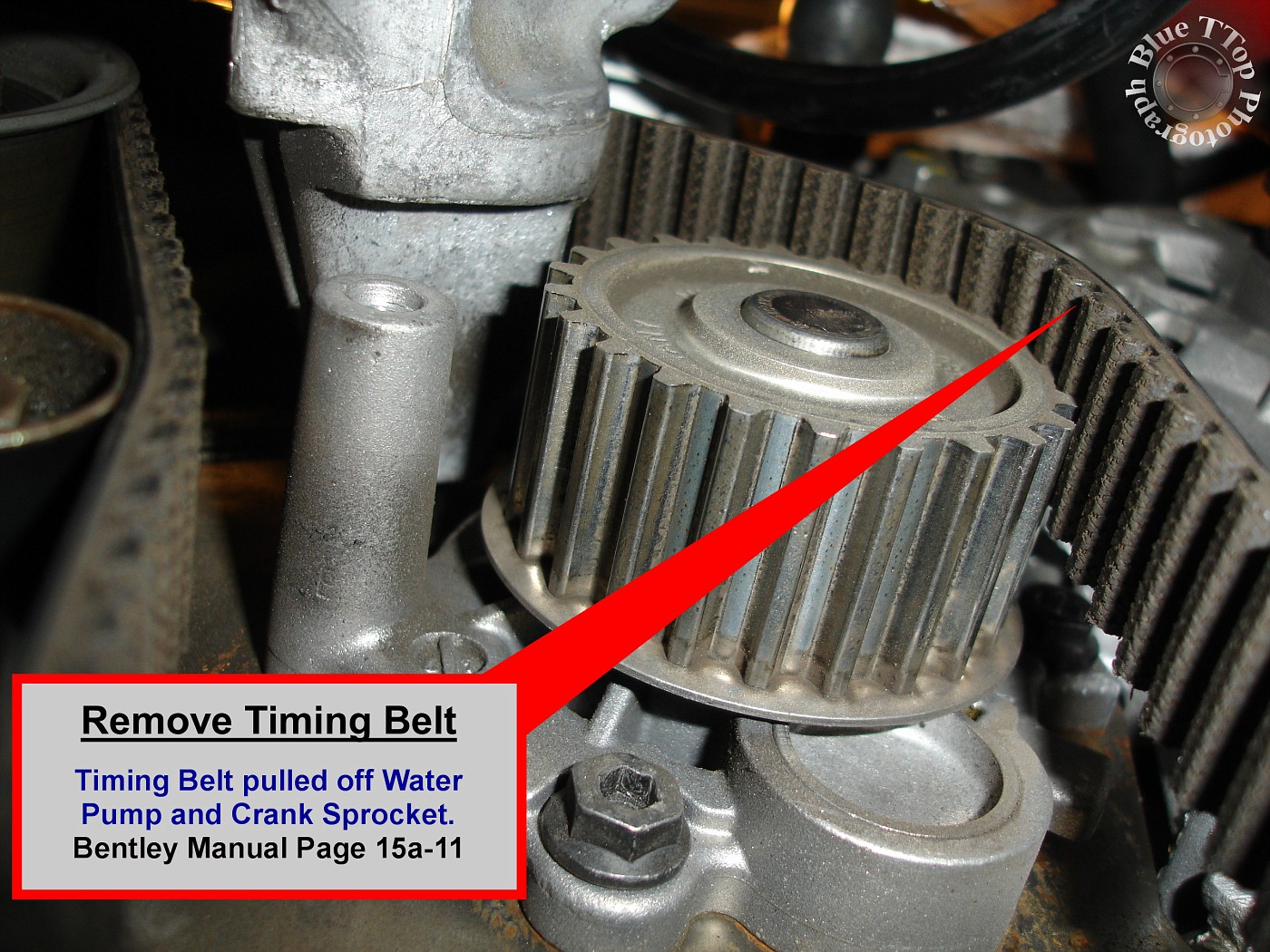
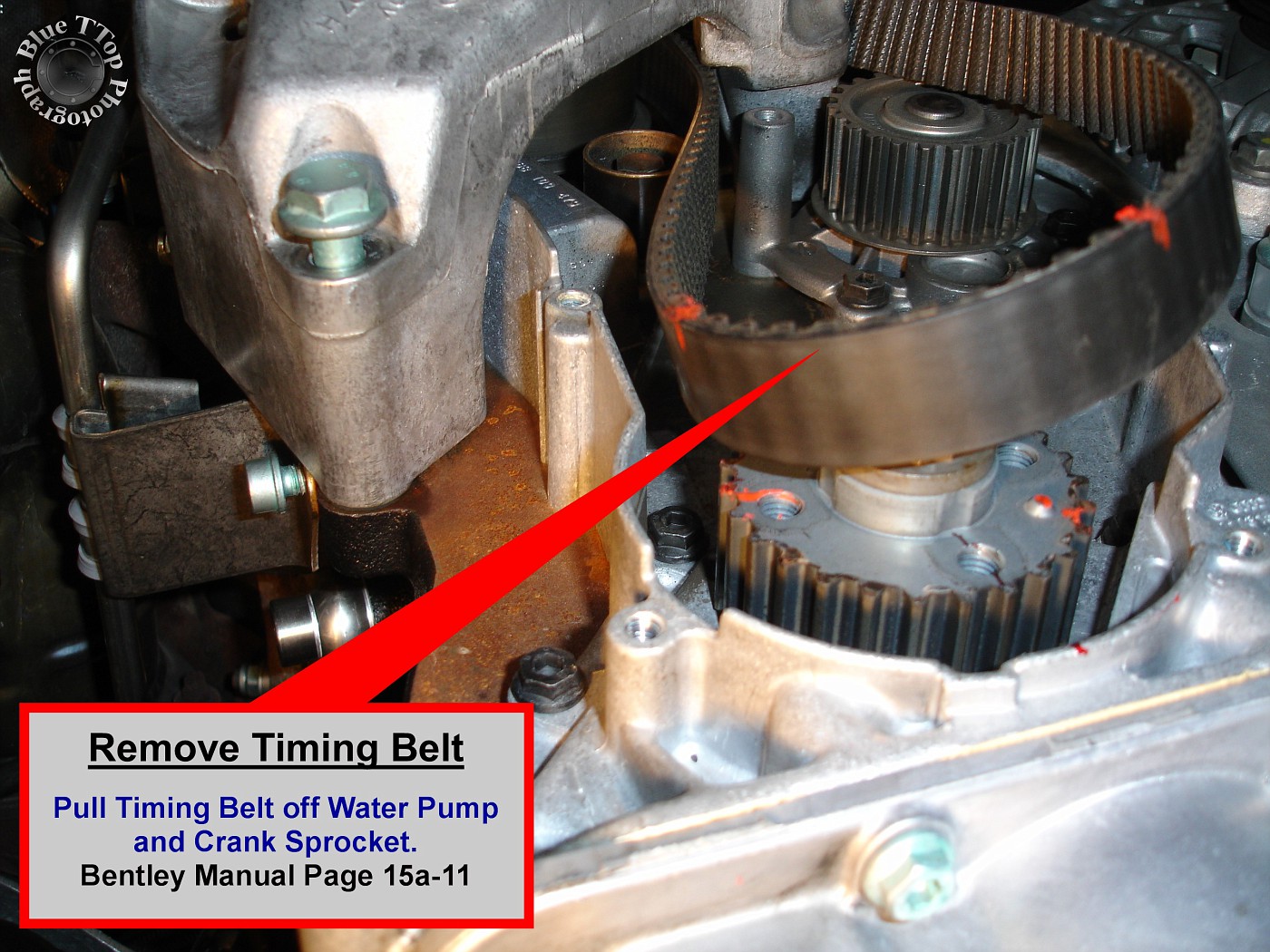
Step 18: Pull Timing Belt off the Water Pump and Crank Sprocket.
Work the Timing Belt off the Water Pump and Crank Sprocket by alternating pulls at each location. NOTE: At this point you can remove the Timing Belt completely by wiggling it out under the Engine Mount Bracket. Set the Belt aside in a dry place until marks can be transferred to the new Timing Belt. Bentley Manual page 15a-11.
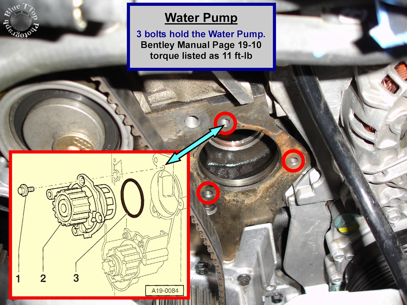
Step 19: Remove Water Pump.
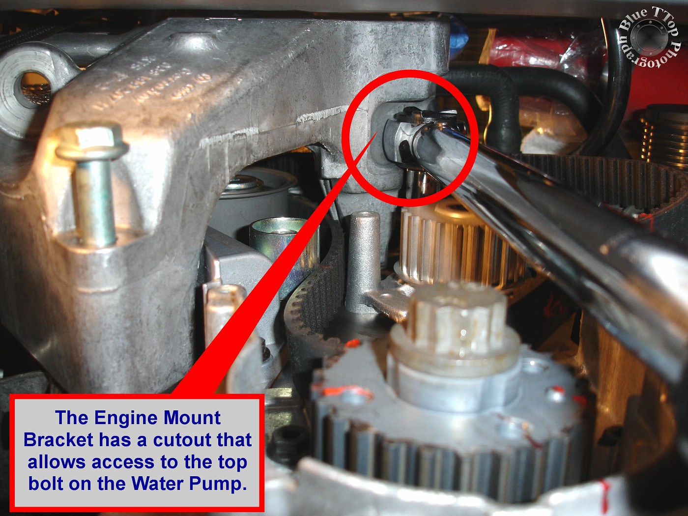
Removing the Water Pump can be a real challenge. Start by removing the 3 bolts (10mm) that hold the Water Pump to the engine. The Dieselgeek Timing Belt Kit came with special-made Water Pump removal screws that force the pump out of the engine without damaging the surface. Apply a good amount of grease to the threads on the removal screws (I used white lithium). Insert a removal screw into each of the three Water Pump mounting holes. Take turns to evenly tighten each screw until it is all the way in, or the Water Pump comes out. With a pair of gloves combined with some prying and the Water Pump came out. NOTE: Expect this to take a good amount of effort and be prepared for a large amount of coolant to drain at the Water Pump when removed. Rags and a bucket were used to keep the draining coolant under control and away from the Crank Sprocket. Bentley Manual page 19-10.
Access to the top bolt on the Water Pump is possible due to the shape of the Engine Mount Bracket.
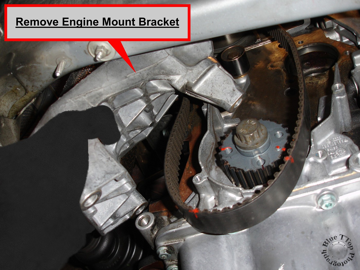
Step 20: Remove Engine Mount Bracket.
Lower the engine slightly and remove the last remaining bolt in the Engine Mount Bracket. This bolt was accessed from below and was reached with a deep socket. With the Water Pump already out of the way, the Engine Mount Bracket can be lowered, turned, and removed. NOTE: Removal of the bracket will allow use of a 3/8" Torque Wrench on all replacement part bolts.
There is plenty of room to work with Engine Mount Bracket removed.
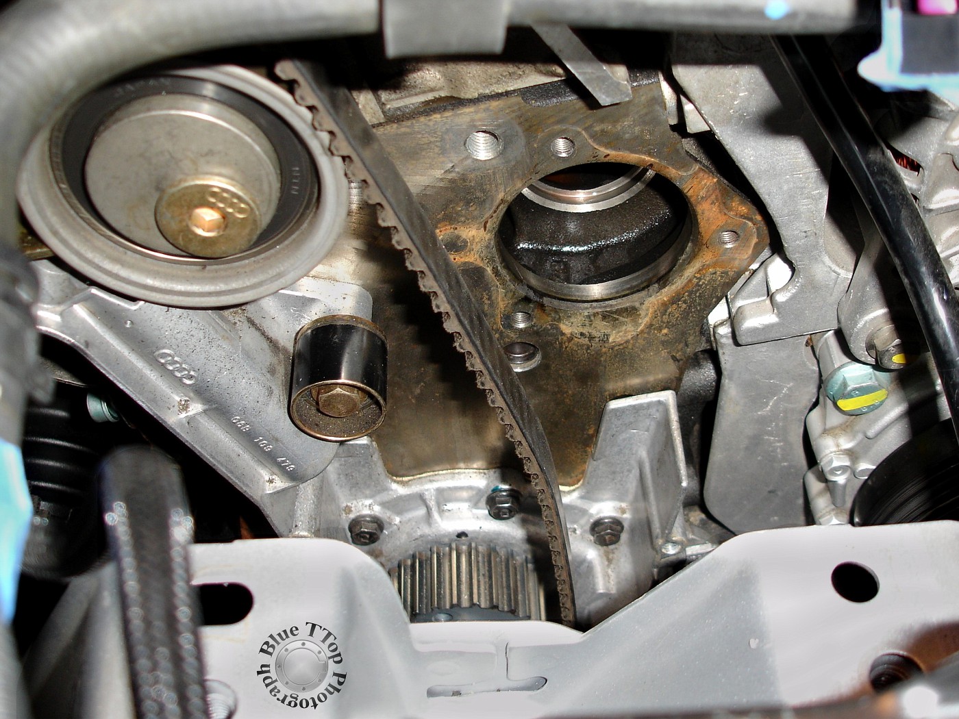
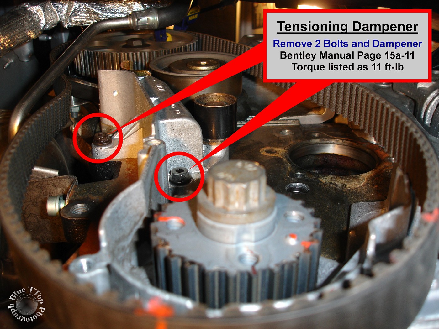
Step 21: Remove Tensioning Dampener.
Remove the 2 bolts (10mm) and Tensioning Dampener. Bentley Manual page 15a-11.
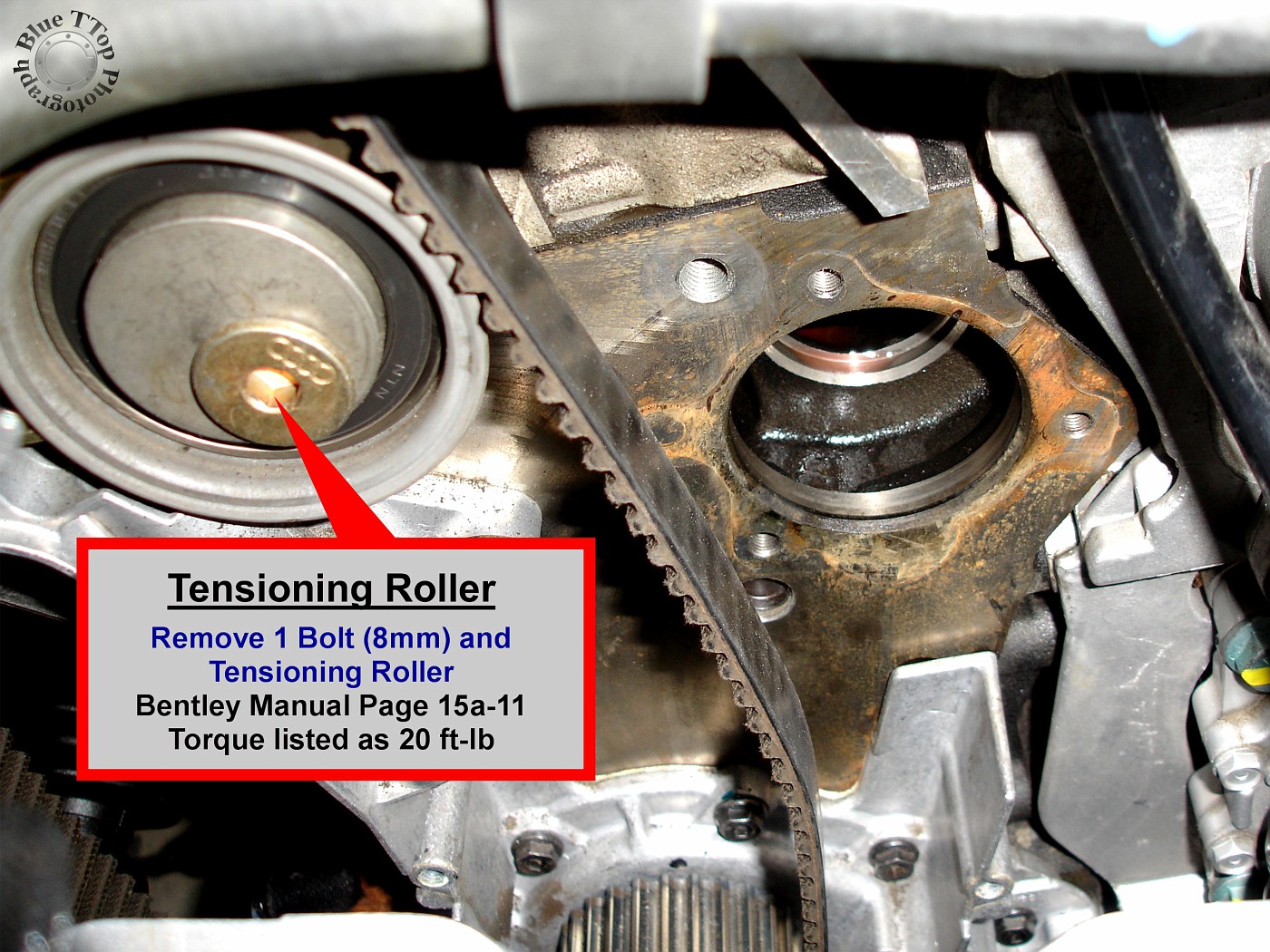
Step 22: Remove Tensioning Roller.
Remove the one bolt (8mm allen-head) and Tensioning Roller. Bentley Manual 15a-11.
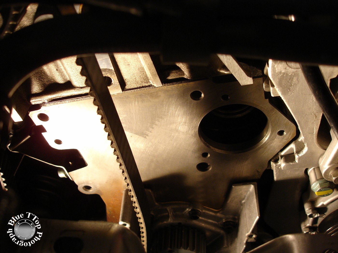
Step 23: Clean Engine and prepare for installation of new parts.
Use rags and an abrasive pad to clean the side of the engine prior to installation of new parts.
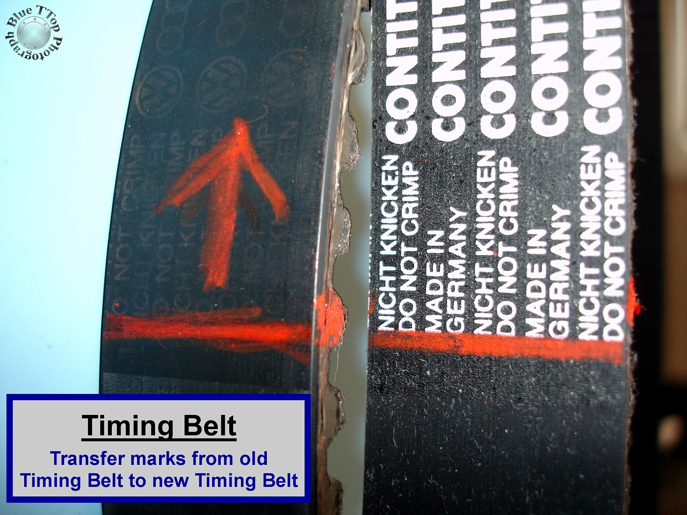
Step 24: Remove old Timing Belt and transfer marks to New Timing Belt.
If you haven't already, release the clamp on the Cam Sprocket and remove the old Timing Belt. Careful counting resulted in a total of 150 teeth on the Timing Belt. Counting from the TDC mark on the Cam Sprocket to the Nub on the Crank Sprocket resulted in a total of 68 teeth.
Reproduce markings from the old Timing Belt to the new Timing Belt. Markings on the new Timing Belt should include a line for TDC, a directional arrow, and an indication of the 68th Tooth.
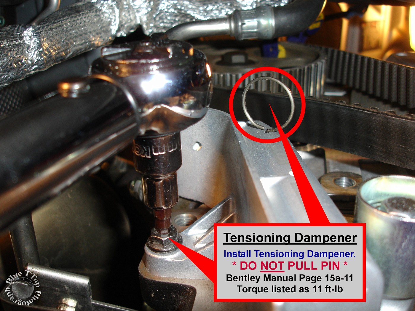
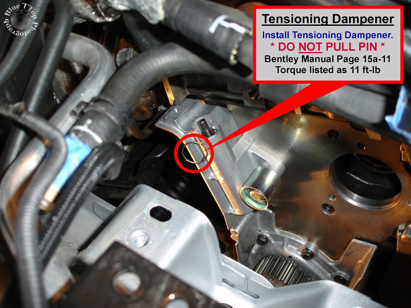
Step 25: Install new Tensioning Dampener.
Install new Tensioning Dampener with existing 2 bolts (10mm). High temperature Threadlocker was applied to bolt threads. Note: Do NOT remove Securing Pin from Tensioning Dampener. Tightening torque listed as 11 ft-lb. Bentley Manual page 15a-11.
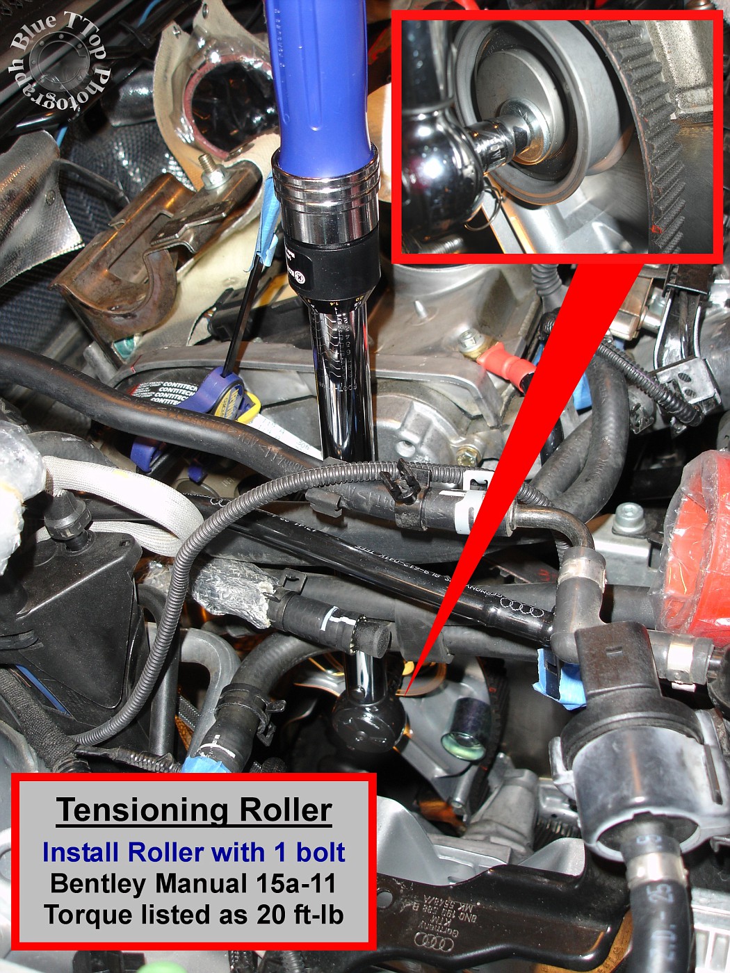
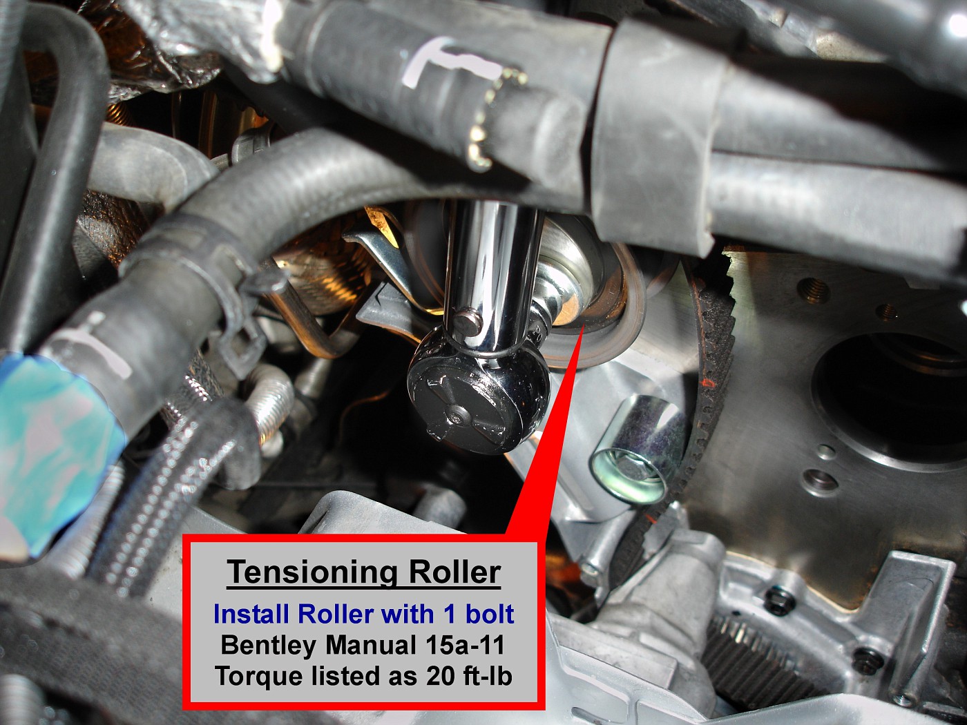
Step 26: Install new Tensioning Roller.
Install the new Tensioning Roller and washer with new 8mm allen-head bolt. The Tensioning Roller was installed from the engine bay to allow use of a torque wrench. High temperature Threadlocker was applied to bolt threads. Bentley Manual page 15a-11. Tightening torque listed as 20 ft-lb.
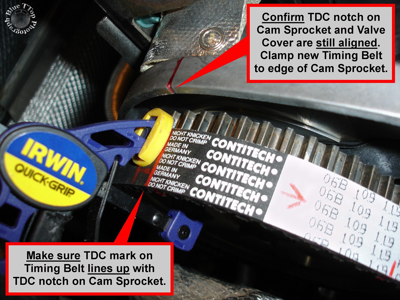
Step 27: Clamp new Timing Belt to Cam Sprocket.
Clamp the new Timing Belt to the Cam sprocket about 1/4" in from the edge. Make sure the transferred TDC mark on the new Timing Belt is aligned with TDC notch on Cam Sprocket and Valve Cover.
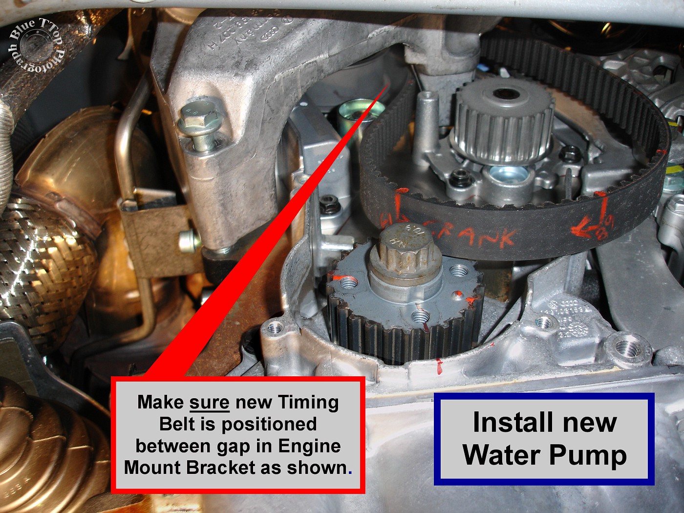
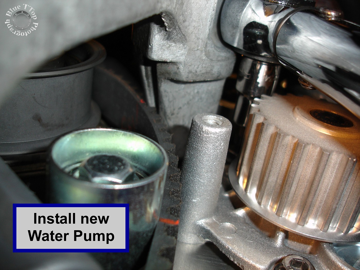
Step 28: Position the Engine Mount Bracket and install new Water Pump.
Before installing the new Water Pump make sure to position the Engine Mount Bracket as shown in the photo below. Make sure the new Timing Belt is positioned in between the gap of the Engine Mount Bracket.

Move the Engine Mount Bracket up into position and use a couple bolts to hold it loosely in place (do not torque). Lubricate the O-Ring on the new Water Pump with coolant. Make sure the O-Ring sealing surface on the engine is clean and smooth. Carefully insert the new Water Pump into the engine block by pushing it slowly with a slight twisting motion. Make sure the O-Ring does not get caught. Install existing 3 Water Pump bolts (10mm). Tightening torque is listed as as 11 ft-lb. Bentley Manual page 19-10.
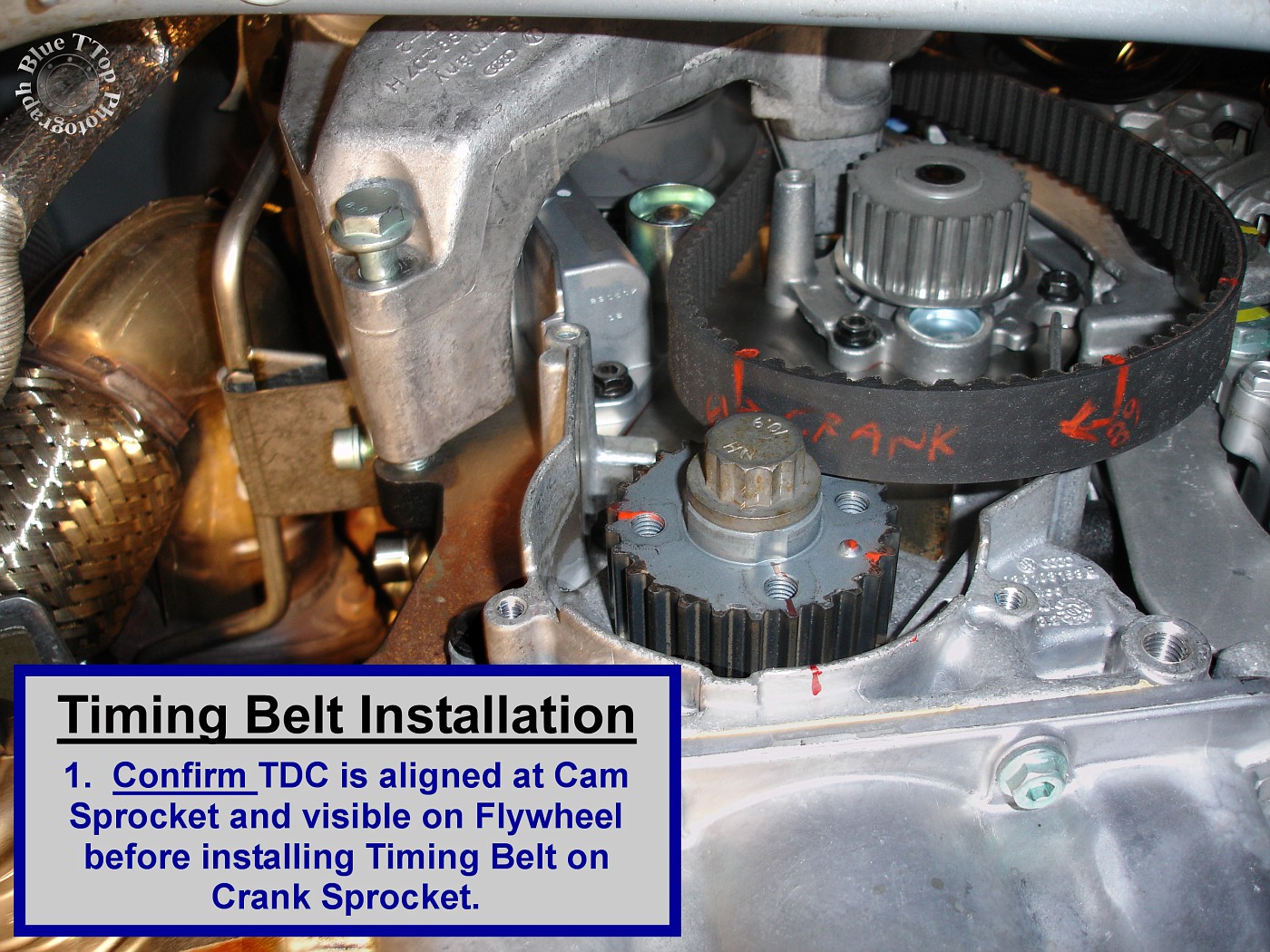
Step 29: Install Timing Belt on Crank Sprocket.
Start by confirming that TDC is aligned at Cam Sprocket and visible on the Flywheel. If TDC is not visible on the Flywheel, then use a 19mm socket to rotate the Crank Sprocket clockwise until TDC is visible in center of Transmission inspection hole.

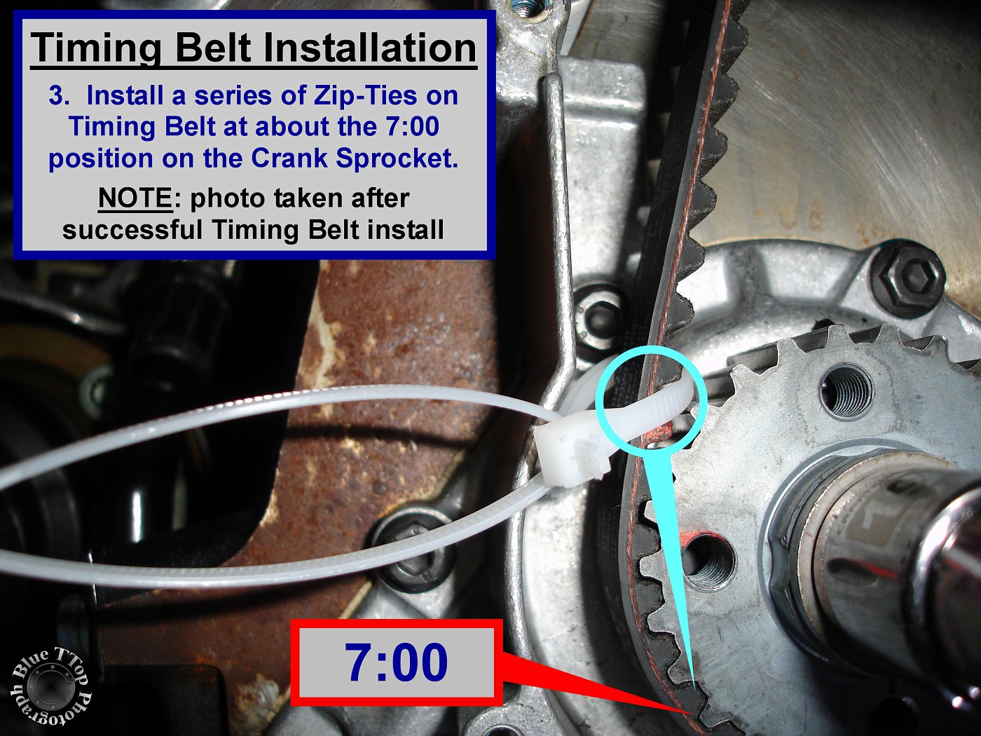
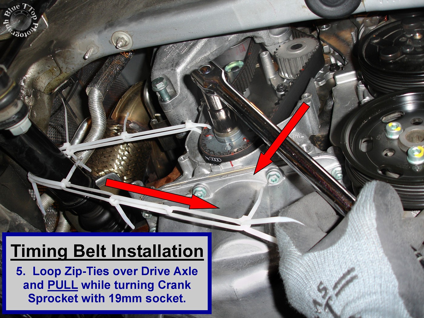
The Timing Belt is so tight that it will tend to "jump" off the Crank Sprocket before you can complete installation.
At about the 7:00 position on the Crank Sprocket temporarily install a series of Zip-Ties. Make a chain long enough to loop them over the Drive Axle back to the Crank Sprocket.
Place a good-sized breaker-bar (or ratchet) with 19mm socket on the Crank Sprocket. Make sure the Timing Belt teeth are synced with the Water Pump gear about ¼" in from the edge. Pull the Timing Belt down to the right side of the Crank Sprocket and match tooth #68 with the nub on the sprocket. The Timing Belt should only be about a ¼" in from the edge of the Crank Sprocket.
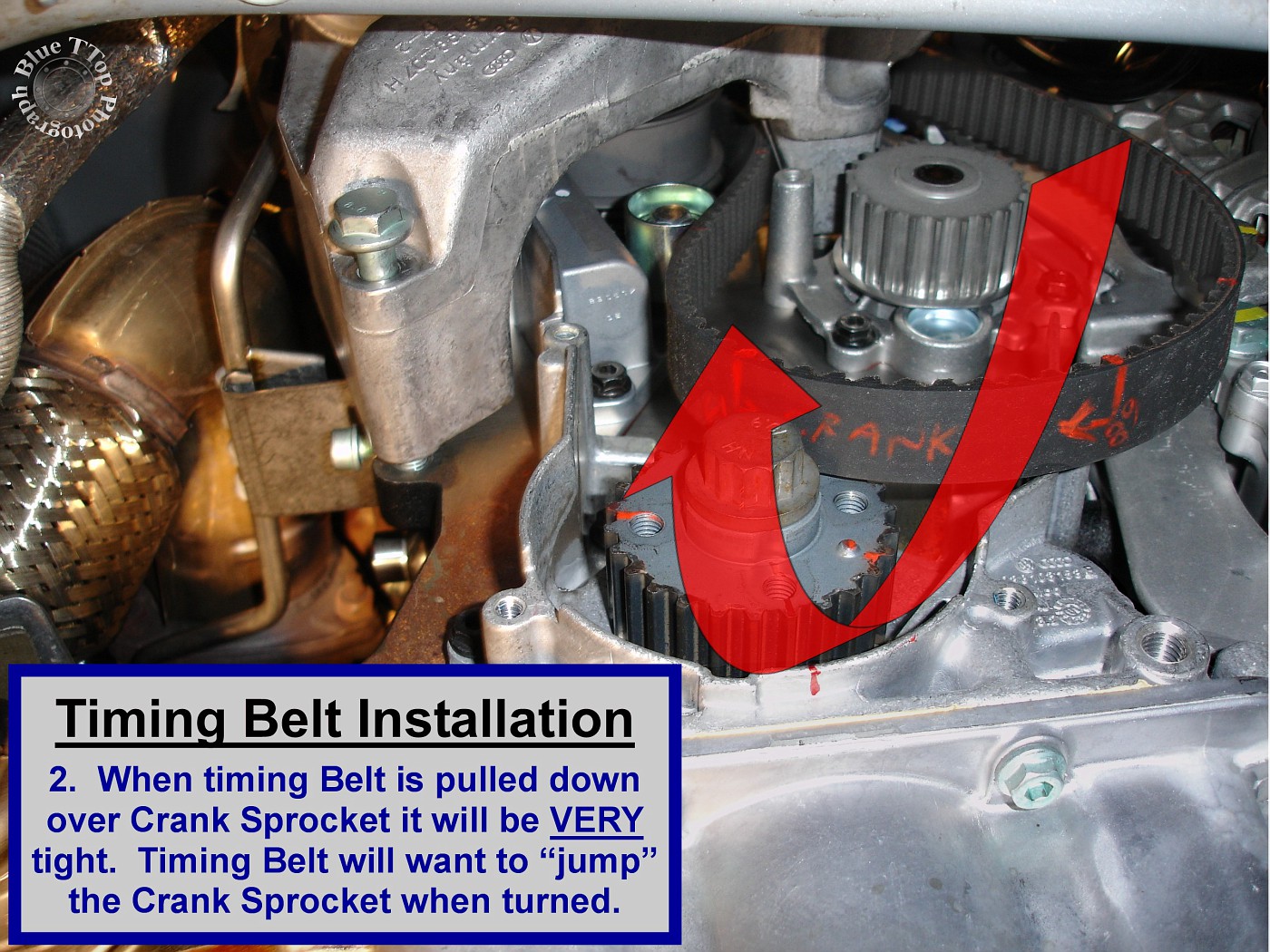
The left hand is going to pull hard on the Zip-Ties while pressing/holding the Timing Belt onto the Crank Sprocket. At the same time, the right hand is going to turn the Crank Sprocket. If the Timing Belt skips a tooth, or jumps off the Crank Sprocket, you have to start over. It may take a few attempts to get the feel and complete the install. When you are successful at getting the Timing Belt to stay on the Crank Sprocket you must remove the clamp holding the belt on the Cam Sprocket. NOTE: Be sure that tooth #68 stays in line with the nub on Crank Sprocket.
If the Timing Belt comes off: Start over by going back to confirm TDC alignment on the Cam Sprocket. It is okay to unclamp the Timing Belt and rotate the Cam Sprocket (clockwise) to get TDC aligned with the notch on the Valve Cover. Clamp the new Timing Belt back on the Cam Sprocket about ¼" in from the edge. Then Confirm TDC on Flywheel. Slight movement of the Crank Sprocket will move the TDC notch on the Flywheel. Just rotate the Crank Sprocket clockwise until TDC is again obtained on the Flywheel and centered in the Transmission inspection hole.
Take turns pushing the Timing Belt onto the various components (Water Pump, Cam Sprocket, Crank Sprocket, and Tensioning Roller) while rotating the Crank or Cam Sprocket clockwise. As you rotate the new Timing Belt you MUST feel for any resistance indicating valves might be hitting pistons. If so, remove the belt and start over. It is normal to have compression pressure from turning the Crank Sprocket, unless you have removed spark plugs. NOTE: Do NOT pull the Securing Pin out of the Tensioning Dampener.
Once the Timing Belt is pushed on all the various components it is time to confirm proper installation. Use a ratchet and socket to rotate the Cam Sprocket to align the TDC notch with the Valve Cover. Check the Flywheel to be sure the TDC notch is visible. If it is NOT visible then timing is off and the Timing Belt must be reinstalled. If the TDC notch is visible on the Flywheel, then rotate the Crank Sprocket two complete turns clockwise. Again, you MUST feel for resistance indicating valves might be hitting pistons. After two complete rotations of the Crank Sprocket, check for TDC alignment. The notch on the Flywheel should be visible and centered at the same time that the TDC notch on the Cam Sprocket lines up with the notch on the Valve Cover.
Step 30: Remove Securing Pin from Tensioning Dampener.
Remove the Securing Pin from the Tensioning Dampener with needle-nose pliers. If needed, loosen the Engine Mount Bracket enough to provide the room to remove the pin. Bentley Manual page 15a-15
Step 31: Reinstall Middle Timing Belt Cover.
Reinstall the Middle Timing Belt Cover using the existing 1 - 10mm hex-head bolt. With the Engine Mount Bracket still loose, the Middle Timing Belt Cover can be positioned into place. NOTE: A small part of the Middle Timing Belt Cover is positioned behind the Accessory Pulley Bracket. Tightening torque is listed as 7 ft-lb. Bentley Manual page 15a-11.
Step 32: Reinstall Lower Timing Belt Cover.
Reinstall the Lower Timing Belt Cover over the Crank Sprocket using the existing 4 - 10mm hex-head bolts. Tightening torque is listed as 7 ft-lb. Bentley Manual page 15a-11.
Step 33: Reinstall Engine Mount Bracket.
The Engine Mount Bracket should already be in position. Installation of remaining bolts will require moving the engine slightly up and down. Tightening torque for all 3 Engine Mount Bracket bolts is listed as 33 ft-lb. Bentley Manual page 15a-15.
Step 34: Reinstall Engine Mount.
A total of 4 new one-time-use stretch-bolts are required to reinstall the Engine Mount. The 2 bolts that attach the Engine Mount to the Engine Mount Bracket are Part# N-102-096-03. The 2 bolts that attach the Engine Mount to the Body are Part# N-105-167-01.
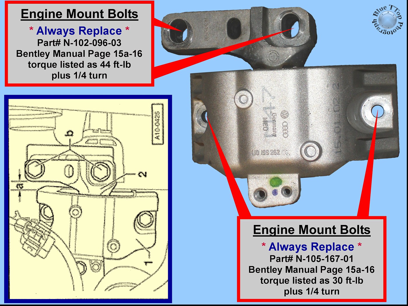
Place the Engine Mount back into position. Raise or lower the engine carefully until the Engine Mount is equally supported by the Body and the Engine Mount Bracket. Confirm that all 4 bolt-holes are aligned. Insert 2 new bolts into Body (16mm head). Use a 16mm socket to confirm these bolts are properly threaded into Body. Tightening torque is listed as 30 ft-lb plus � turn. Insert 2 new bolts into Engine Mount Bracket (18mm head). Use an 18mm socket with little force to confirm bolts are properly threaded into Engine Mount Bracket. Tightening torque is listed as 44 ft-lb plus � turn.
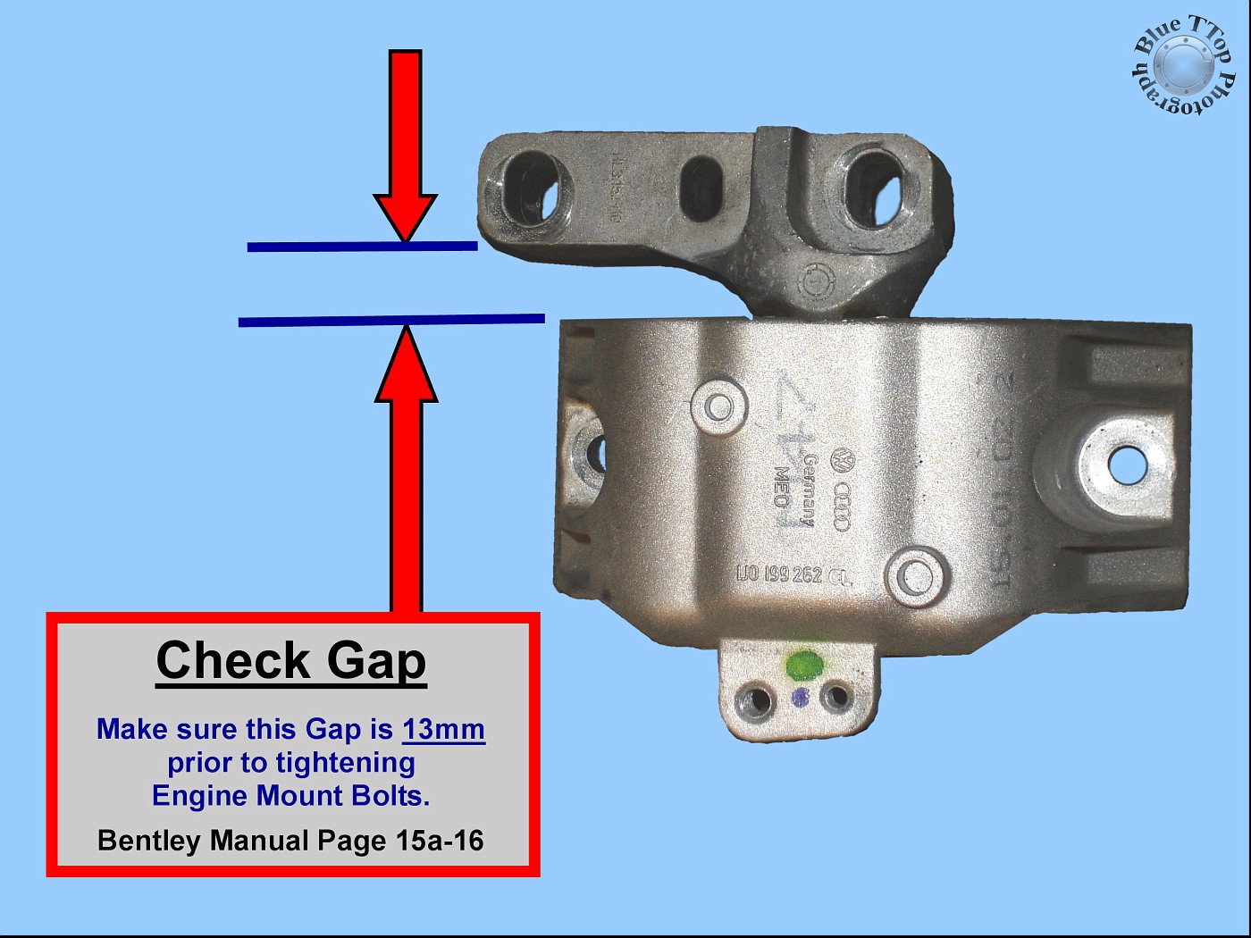
NOTE: Confirm this Gap is approximately 13mm prior to tightening Engine Mount Bolts. Adjust Engine as necessary to obtain proper Gap. Bentley Manual page 15a-16.
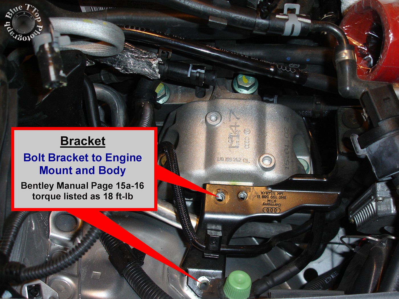
Reinstall bracket between Engine Mount and Body using 2 existing 13mm hex-head bolts. Tightening torque is listed as 18 ft-lb.
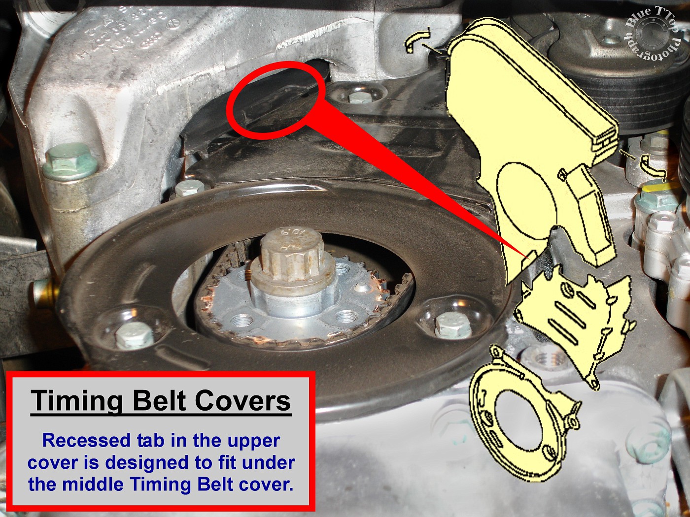
Step 35: Reinstall Upper Timing Belt Cover.
Gently persuade the Upper Timing Belt Cover back into position. A small tab on the lower part of the Upper Timing Belt Cover fits under the Middle Timing Belt Cover. This can be properly positioned and confirmed from underneath. Then secure the 2 clips that hold the Upper Timing Belt Cover to the Valve Cover.
Step 36: Reinstall Crank Pulley.
Reinstall Crank Pulley over Crank Sprocket using existing 4 allen-head bolts. Use a 19mm socket on the Crank Sprocket to hold-back and tighten the bolts. Tightening torque is listed as 18 ft-lb.
Step 37: Reinstall Tensioner and new Ribbed Belt.
Position the Tensioner back into place and install with existing 3 - 13mm hex-head bolts. Make sure to also reinstall the Charge Pipe bracket held by the top 2 bolts. Tightening torque is listed as 18 ft-lb.
Use a 15mm wrench to pull Tensioner toward front bumper to allow Ribbed Belt installation. Make sure the Ribbed Belt is seated in the various pulleys when installing. If reusing a belt, make sure it is installed with the same side up and in the same direction as originally installed. Bentley Manual pages 03-39 and 03-40.
Step 38: Reinstall Power Steering Fluid Reservoir.
Position the Power Steering Fluid Reservoir on top of the Engine Mount. Remove the rubber stoppers in both hoses and reconnect them to the reservoir. Reinstall clamps back into position on each hose. Secure the Power Steering Reservoir with the existing 1 - 5mm allen-head bolt. Tightening torque is listed as 7 ft-lb.
Remove the Power Steering Fluid Reservoir filler cap using a wrench or screwdriver. Clean the dipstick and reinstall the filler cap. Remove the filler cap to check fluid level, which will be low due to loss during reservoir removal. Add G-004 power steering fluid until between MIN and MAX marks on dipstick. Bentley Manual page 03-31.
Step 39: Reinstall Coolant Reservoir.
Reconnect the hose on the bottom of Coolant Reservoir and install clamp. Reconnect the top hose on the reservoir and install clamp. Install the bracket with existing 2 phillips-head screws. Reconnect wire harness to Coolant Reservoir. Bentley Manual page 19-9.
Step 40: Reinstall Charge Pipe.
Reconnect hoses at each end of the Charge Pipe. Make sure the Charge Pipe is seated in both support brackets before tightening hose clamps. Use a 13mm socket to secure the 2 top brackets with existing nuts. Tightening torque is listed as 15 ft-lb. Bentley Manual page 15a-12.
Step 41: Reinstall Strut Tower Bar.
Use a 13mm socket to reinstall the Strut Tower Bar and mounting bracket with existing nuts. Tightening torque listed as 15 ft-lb. Bentley Manual page 40-3.
Step 42: Add Coolant and Start your Engine.
Make sure the Coolant Drain Valve is closed.
Use a clean pitcher for mixing and easy pouring of Coolant into the Coolant Reservoir. For freeze protection down to -31 F, mix equal parts 50/50 of Distilled Water and G-012. NOTE: Do not use tap water.
Slowly fill the Coolant Reservoir with the premixed Coolant and Distilled Water. Repeat this process until Coolant level stabilizes at the MAX mark on the reservoir when the engine is cold. NOTE: Do not pour straight Coolant or straight water into reservoir. Install the Cap on the Coolant Reservoir.
Start the Engine and let it run while watching the Coolant level in the reservoir. If the Coolant Reservoir drains empty, then shut off the Engine and refill up to the MAX mark. Repeat the process until the radiator fans cycle once and the Coolant level does not go below the MIN mark. Bentley Manual page 19-6.
Step 43: Reinstall Wheel-Arch Liner, Sound Absorber Panels, and Wheel.
Use a 10mm socket to reinstall the plastic lower right-side Sound Absorber panel with existing 2 speed nuts. Reinstall the Wheel-Arch Liner with existing hardware. Bentley Manual page 03-16.
Reinstall right-front Wheel. Tightening torque is listed as 89 ft-lb. Bentley Manual page 03-55.
Step 44: Reinstall Engine Covers.
Reinstall Engine Covers. Bentley Manual page 15a-12.
NOTES:
Recheck and verify Coolant level until satisfied. In total I added 4-1/2 quarts. A chart of Antifreeze Protection Levels can be found on Bentley Manual page 03-26.
Check Power Steering fluid reservoir after driving vehicle.
Using a 3/8" drive Torque Wrench, combined with various length sockets, including hex bit sockets, and you will be able to torque everything to OE specifications. I found that 1/2"-Drive is too large for the many tight spaces, especially the Engine Mount Bracket.
Use a digital camera and take a lot of pictures throughout the process. This will definitely be appreciated if you need to go back to see how something was originally installed.
Use some Ziploc plastic bags to sort all the hardware removed. Label the bag with a marker to make reinstallation easier and eliminate lost parts and confusion later on.
Apply Threadlocker to bolts prior to installation ONLY on bolts with blue / green color on threads.
The work in this write up was performed by the author, without assistance, over a number of days. Speed was not the goal of this effort. The author recognizes it is possible to change the sequence of some steps in this write-up. This may be more efficient for others performing the same work.
Additional photos can be found in my Fotki Timing Belt album here: http://public.fotki.com/BlueTTop/mod...t-replacement/
Thanks to Steve at the ModShack for hosting the PDF!
Tools recommended include:
Bentley Publishers Audi TT Service Manual (book or CD), Torque Wrench (3/8" drive recommended), Floor Jacks (2 minimum), Jack Stands (3 minimum), Tool Set including ratchet / extensions / wrenches / metric sockets (various lengths) / hex bit sockets / torx drivers / allen wrenches, Wheel Chocks (2), Small Clamps, and a digital camera to document your progress in case you need to go back and review how it was originally installed.
Supplies recommended include:
3 Liters of VW/Audi G-012 Coolant Antifreeze, 3 Liters of Distilled Water, 1/2-gallon Clear plastic pitcher (for mixing distilled water and Coolant), 1 Liter of VW/Audi G-004 Power Steering Fluid (a lot less is needed), Loctite high temperature Threadlocker, Bucket & Hose to drain coolant (hose ID approximately 10mm), Shop Towels/Rags, Plastic Bags (Ziploc), Zip Ties, Rubber Stoppers (to plug coolant and power steering hoses), Marking Pen (Red China Marker), and an Abrasive Pad (ScotchBrite).
A Dieselgeek Timing Belt replacement kit was purchased with all the necessary replacement parts. The kit included a new Timing Belt, Tensioning Roller, Ribbed Belt, Tensioning Dampener, Engine Mount Bolts, and Water Pump with metal impeller: http://www.dieselgeek.com/Audi_TT_GT...kit_s/1833.htm
Step 1: Preparation.
In preparation make sure the car is on a level surface with enough room to place a floor jack on both sides. Engage the Emergency Brake and Chock the rear wheels. Carefully raise the vehicle and place it on Jack Stands. DO NOT ATTEMPT this if you are unsure of how to safely lift the vehicle or properly place Jack Stands! The Bentley Service Manual includes information on Lifting Vehicle and Working under the Vehicle on pages 03-11 through 03-13.
Step 2: Remove Engine Covers and Charge Pipe.
Remove the plastic covers over the engine and coolant reservoir. Bentley Manual page 03-15.
Then remove the Charge Pipe so you have easy access to the Timing Belt Cover and Engine Mount below it. Bentley Manual page 15a-12.
Step 3: Remove Strut Tower Bar (optional).
This is optional, but was found to improve access and made removal of the Timing Belt Cover much easier. Use a 13mm socket to remove Strut Tower Bar and right-side mounting bracket. Bentley Manual page 40-3.
Step 4: Remove Wheel, Sound Absorber Panels, and Wheel-Arch Liner.
Remove the right front wheel. Remove the plastic Wheel-Arch Liner. Remove the plastic lower Sound Absorber Panel (under tray) and the plastic lower right-side Sound Absorber Panel. Bentley Manual page 03-16.
Step 5: Drain Coolant.
Remove cap from Coolant Reservoir. NOTE: Make sure the engine is cool! Place hose end in a bucket and attach the other end to the Coolant Drain Valve. Turn Valve **** counter clockwise and pull out to open and drain coolant. Bentley Manual page 19-5.
Step 6: Remove Coolant Reservoir.
Disconnect and remove the Coolant Reservoir. The tank had yellowed over time and was also replaced. Disconnect the Wire Harness on top of the tank. Then remove the 2 Phillips-head screws. Bentley Manual page 19-9. Disconnect the hose visible on top of the tank first. Then lift the tank to expose and remove the lower hose connection. Insert rubber stoppers to prevent dripping.
Rubber stoppers in various sizes available at any hardware store.
Existing 6-year old tank on left compared to new tank.
Step 7: Remove Power Steering fluid reservoir.
Power Steering reservoir is held in place by 1 - 5mm allen-head bolt and 2 hoses. The picture below shows how the reservoir sits on top of the Engine Mount. Bentley Manual page 03-31.
Remove the single bolt holding the reservoir. I then put some paper towels inside a Ziploc bag and positioned one under each hose connection. Disconnect the hose and let the fluid drain into the bag. Then insert a rubber stopper into each hose to prevent dripping.
With the Power Steering reservoir removed the Engine Mount is now completely exposed.
Step 8: Remove the Ribbed Belt and Tensioner.
Use a 15mm wrench on top of the Tensioner and pull forward towards front bumper. While pulling the wrench forward the tension on the ribbed belt will be relieved and the belt can be removed. Bentley Manual pages 03-39 and 03-40.
The Tensioner can be seen from underneath in this picture.
View of engine bay location where Tensioner can be accessed to release Ribbed Belt.
Once the Ribbed Belt is removed the Tensioner can be removed. It is held in place by 3 - 13mm head bolts. Remove the 3 bolts and remove the Tensioner. A bracket holding the Charge Pipe will also be removed. Tightening torque for these 3 bolts is listed as 18 ft-lb. NOTE: If Ribbed Belt is going to be reused, mark direction of the belt before removal.
Step 9: Remove Crank Pulley.
Remove Crank Pulley by removing 4 allen-head bolts. Tightening torque for these 4 bolts is listed as 18 ft-lb. Use a 19mm socket on Crank Gear to hold back on pulley to loosen bolts.
This picture shows Crank Pulley removed and lower timing belt cover exposed.
Step 10: Remove Upper Timing Belt Cover.
Unclip the top Timing Belt cover by releasing both clips (front and back). It will take some careful finagling, but with the Strut Tower Bar already removed it was much easier to remove and install.
Step 11: Remove Engine Mount.
Proper support of the Engine is CRITICAL. This work should be done with an engine hoist or engine support bar designed for this purpose (see inset on photo below). Bentley Manual page 15a-13. Supporting the engine underneath with a jack and jack stand is dangerous and not recommended.
Start by removing the 2 bolts that hold a bracket on top of the Engine Mount. Then, with the engine properly supported, the 4 one-time-use stretch-bolts holding the Engine Mount can be removed. The 2 bolts nearest to the fender can be removed with a 16mm socket (Part # N-105-167-01). The 2 bolts closer to the engine can be removed with an 18mm socket (Part # N-102-096-03). NOTE: All 4 bolts must be replaced. Bentley Manual page 15a-16.
This photo shows the Engine Mount removed and the Engine Mount Bracket exposed.
The Engine Mount removed from the vehicle.
Step 12: Loosen Engine Mount Bracket.
The Engine Mount Bracket is bolted to the side of the engine with 3 bolts. Remove the upper-front and lower-rear bolts. The upper-front bolt can be accessed from the engine bay. Raise the engine slightly until bolt can be removed as shown in photo. Bentley Manual page 15a-15.
Lower the engine slightly to remove the lower-rear bolt shown in photo. Then, using a deep socket, loosen the remaining bolt to allow the Engine Mount Bracket to pivot (will allow removal of the Middle Timing Belt Cover).
Step 13: Remove Lower Timing Belt Cover.
Lower Timing Belt Cover is held in place by 4 - 10mm hex-head bolts shown in photo. Tightening torque is listed as 7 ft-lb. Bentley Manual page 15a-11.
Step 14: Remove Middle Timing Belt Cover.
Middle Timing Belt Cover is held in place by 1 - 10mm hex-head bolt shown in photo below. Tightening torque is listed as 7 ft-lb. Bentley Manual page 15a-11.
NOTE: Removal of Middle Timing Belt Cover is much easier if Engine Mount Bracket is already loose and able to pivot slightly.
Step 15: Align Top Dead Center (TDC) marks on Cam Sprocket and Valve Cover.
Use a socket on the center bolt of the Cam Sprocket to rotate clockwise until TDC marks are aligned. Then clamp the Timing Belt to the Cam Sprocket to eliminate slippage later on. Bentley Manual page 15a-13.
Mark the Timing Belt at the location where the TDC notch on the Cam Sprocket lines up with the TDC notch on the Valve Cover. Mark the direction of the belt with an arrow (clockwise). Note: Use a marker that will not easily rub or wash off.
Step 16: Confirm TDC mark on Flywheel.
Remove rubber cap on Transmission to view TDC mark on Flywheel.
If TDC is aligned on Cam Sprocket and Valve Cover, then TDC notch on Flywheel should be visible as shown in this photo. Note: Do NOT remove Timing Belt until TDC confirmed at both the Cam Sprocket and the Flywheel. Bentley Manual page 15a-15.
Step 17: Mark Timing Belt at Crank Sprocket.
Once TDC is confirmed at Cam Sprocket and Flywheel it is time to mark the Timing Belt at the Crank Sprocket. Mark the raised nub on the Crank Sprocket and the adjacent Timing Belt tooth. NOTE: Markings on the Timing Belt need to be clear and NOT easily removed. These marks will need to be transferred to the new Timing Belt prior to installation.
Step 18: Pull Timing Belt off the Water Pump and Crank Sprocket.
Work the Timing Belt off the Water Pump and Crank Sprocket by alternating pulls at each location. NOTE: At this point you can remove the Timing Belt completely by wiggling it out under the Engine Mount Bracket. Set the Belt aside in a dry place until marks can be transferred to the new Timing Belt. Bentley Manual page 15a-11.
Step 19: Remove Water Pump.
Removing the Water Pump can be a real challenge. Start by removing the 3 bolts (10mm) that hold the Water Pump to the engine. The Dieselgeek Timing Belt Kit came with special-made Water Pump removal screws that force the pump out of the engine without damaging the surface. Apply a good amount of grease to the threads on the removal screws (I used white lithium). Insert a removal screw into each of the three Water Pump mounting holes. Take turns to evenly tighten each screw until it is all the way in, or the Water Pump comes out. With a pair of gloves combined with some prying and the Water Pump came out. NOTE: Expect this to take a good amount of effort and be prepared for a large amount of coolant to drain at the Water Pump when removed. Rags and a bucket were used to keep the draining coolant under control and away from the Crank Sprocket. Bentley Manual page 19-10.
Access to the top bolt on the Water Pump is possible due to the shape of the Engine Mount Bracket.
Step 20: Remove Engine Mount Bracket.
Lower the engine slightly and remove the last remaining bolt in the Engine Mount Bracket. This bolt was accessed from below and was reached with a deep socket. With the Water Pump already out of the way, the Engine Mount Bracket can be lowered, turned, and removed. NOTE: Removal of the bracket will allow use of a 3/8" Torque Wrench on all replacement part bolts.
There is plenty of room to work with Engine Mount Bracket removed.
Step 21: Remove Tensioning Dampener.
Remove the 2 bolts (10mm) and Tensioning Dampener. Bentley Manual page 15a-11.
Step 22: Remove Tensioning Roller.
Remove the one bolt (8mm allen-head) and Tensioning Roller. Bentley Manual 15a-11.
Step 23: Clean Engine and prepare for installation of new parts.
Use rags and an abrasive pad to clean the side of the engine prior to installation of new parts.
Step 24: Remove old Timing Belt and transfer marks to New Timing Belt.
If you haven't already, release the clamp on the Cam Sprocket and remove the old Timing Belt. Careful counting resulted in a total of 150 teeth on the Timing Belt. Counting from the TDC mark on the Cam Sprocket to the Nub on the Crank Sprocket resulted in a total of 68 teeth.
Reproduce markings from the old Timing Belt to the new Timing Belt. Markings on the new Timing Belt should include a line for TDC, a directional arrow, and an indication of the 68th Tooth.
Step 25: Install new Tensioning Dampener.
Install new Tensioning Dampener with existing 2 bolts (10mm). High temperature Threadlocker was applied to bolt threads. Note: Do NOT remove Securing Pin from Tensioning Dampener. Tightening torque listed as 11 ft-lb. Bentley Manual page 15a-11.
Step 26: Install new Tensioning Roller.
Install the new Tensioning Roller and washer with new 8mm allen-head bolt. The Tensioning Roller was installed from the engine bay to allow use of a torque wrench. High temperature Threadlocker was applied to bolt threads. Bentley Manual page 15a-11. Tightening torque listed as 20 ft-lb.
Step 27: Clamp new Timing Belt to Cam Sprocket.
Clamp the new Timing Belt to the Cam sprocket about 1/4" in from the edge. Make sure the transferred TDC mark on the new Timing Belt is aligned with TDC notch on Cam Sprocket and Valve Cover.
Step 28: Position the Engine Mount Bracket and install new Water Pump.
Before installing the new Water Pump make sure to position the Engine Mount Bracket as shown in the photo below. Make sure the new Timing Belt is positioned in between the gap of the Engine Mount Bracket.
Move the Engine Mount Bracket up into position and use a couple bolts to hold it loosely in place (do not torque). Lubricate the O-Ring on the new Water Pump with coolant. Make sure the O-Ring sealing surface on the engine is clean and smooth. Carefully insert the new Water Pump into the engine block by pushing it slowly with a slight twisting motion. Make sure the O-Ring does not get caught. Install existing 3 Water Pump bolts (10mm). Tightening torque is listed as as 11 ft-lb. Bentley Manual page 19-10.
Step 29: Install Timing Belt on Crank Sprocket.
Start by confirming that TDC is aligned at Cam Sprocket and visible on the Flywheel. If TDC is not visible on the Flywheel, then use a 19mm socket to rotate the Crank Sprocket clockwise until TDC is visible in center of Transmission inspection hole.
The Timing Belt is so tight that it will tend to "jump" off the Crank Sprocket before you can complete installation.
At about the 7:00 position on the Crank Sprocket temporarily install a series of Zip-Ties. Make a chain long enough to loop them over the Drive Axle back to the Crank Sprocket.
Place a good-sized breaker-bar (or ratchet) with 19mm socket on the Crank Sprocket. Make sure the Timing Belt teeth are synced with the Water Pump gear about ¼" in from the edge. Pull the Timing Belt down to the right side of the Crank Sprocket and match tooth #68 with the nub on the sprocket. The Timing Belt should only be about a ¼" in from the edge of the Crank Sprocket.
The left hand is going to pull hard on the Zip-Ties while pressing/holding the Timing Belt onto the Crank Sprocket. At the same time, the right hand is going to turn the Crank Sprocket. If the Timing Belt skips a tooth, or jumps off the Crank Sprocket, you have to start over. It may take a few attempts to get the feel and complete the install. When you are successful at getting the Timing Belt to stay on the Crank Sprocket you must remove the clamp holding the belt on the Cam Sprocket. NOTE: Be sure that tooth #68 stays in line with the nub on Crank Sprocket.
If the Timing Belt comes off: Start over by going back to confirm TDC alignment on the Cam Sprocket. It is okay to unclamp the Timing Belt and rotate the Cam Sprocket (clockwise) to get TDC aligned with the notch on the Valve Cover. Clamp the new Timing Belt back on the Cam Sprocket about ¼" in from the edge. Then Confirm TDC on Flywheel. Slight movement of the Crank Sprocket will move the TDC notch on the Flywheel. Just rotate the Crank Sprocket clockwise until TDC is again obtained on the Flywheel and centered in the Transmission inspection hole.
Take turns pushing the Timing Belt onto the various components (Water Pump, Cam Sprocket, Crank Sprocket, and Tensioning Roller) while rotating the Crank or Cam Sprocket clockwise. As you rotate the new Timing Belt you MUST feel for any resistance indicating valves might be hitting pistons. If so, remove the belt and start over. It is normal to have compression pressure from turning the Crank Sprocket, unless you have removed spark plugs. NOTE: Do NOT pull the Securing Pin out of the Tensioning Dampener.
Once the Timing Belt is pushed on all the various components it is time to confirm proper installation. Use a ratchet and socket to rotate the Cam Sprocket to align the TDC notch with the Valve Cover. Check the Flywheel to be sure the TDC notch is visible. If it is NOT visible then timing is off and the Timing Belt must be reinstalled. If the TDC notch is visible on the Flywheel, then rotate the Crank Sprocket two complete turns clockwise. Again, you MUST feel for resistance indicating valves might be hitting pistons. After two complete rotations of the Crank Sprocket, check for TDC alignment. The notch on the Flywheel should be visible and centered at the same time that the TDC notch on the Cam Sprocket lines up with the notch on the Valve Cover.
Step 30: Remove Securing Pin from Tensioning Dampener.
Remove the Securing Pin from the Tensioning Dampener with needle-nose pliers. If needed, loosen the Engine Mount Bracket enough to provide the room to remove the pin. Bentley Manual page 15a-15
Step 31: Reinstall Middle Timing Belt Cover.
Reinstall the Middle Timing Belt Cover using the existing 1 - 10mm hex-head bolt. With the Engine Mount Bracket still loose, the Middle Timing Belt Cover can be positioned into place. NOTE: A small part of the Middle Timing Belt Cover is positioned behind the Accessory Pulley Bracket. Tightening torque is listed as 7 ft-lb. Bentley Manual page 15a-11.
Step 32: Reinstall Lower Timing Belt Cover.
Reinstall the Lower Timing Belt Cover over the Crank Sprocket using the existing 4 - 10mm hex-head bolts. Tightening torque is listed as 7 ft-lb. Bentley Manual page 15a-11.
Step 33: Reinstall Engine Mount Bracket.
The Engine Mount Bracket should already be in position. Installation of remaining bolts will require moving the engine slightly up and down. Tightening torque for all 3 Engine Mount Bracket bolts is listed as 33 ft-lb. Bentley Manual page 15a-15.
Step 34: Reinstall Engine Mount.
A total of 4 new one-time-use stretch-bolts are required to reinstall the Engine Mount. The 2 bolts that attach the Engine Mount to the Engine Mount Bracket are Part# N-102-096-03. The 2 bolts that attach the Engine Mount to the Body are Part# N-105-167-01.
Place the Engine Mount back into position. Raise or lower the engine carefully until the Engine Mount is equally supported by the Body and the Engine Mount Bracket. Confirm that all 4 bolt-holes are aligned. Insert 2 new bolts into Body (16mm head). Use a 16mm socket to confirm these bolts are properly threaded into Body. Tightening torque is listed as 30 ft-lb plus � turn. Insert 2 new bolts into Engine Mount Bracket (18mm head). Use an 18mm socket with little force to confirm bolts are properly threaded into Engine Mount Bracket. Tightening torque is listed as 44 ft-lb plus � turn.
NOTE: Confirm this Gap is approximately 13mm prior to tightening Engine Mount Bolts. Adjust Engine as necessary to obtain proper Gap. Bentley Manual page 15a-16.
Reinstall bracket between Engine Mount and Body using 2 existing 13mm hex-head bolts. Tightening torque is listed as 18 ft-lb.
Step 35: Reinstall Upper Timing Belt Cover.
Gently persuade the Upper Timing Belt Cover back into position. A small tab on the lower part of the Upper Timing Belt Cover fits under the Middle Timing Belt Cover. This can be properly positioned and confirmed from underneath. Then secure the 2 clips that hold the Upper Timing Belt Cover to the Valve Cover.
Step 36: Reinstall Crank Pulley.
Reinstall Crank Pulley over Crank Sprocket using existing 4 allen-head bolts. Use a 19mm socket on the Crank Sprocket to hold-back and tighten the bolts. Tightening torque is listed as 18 ft-lb.
Step 37: Reinstall Tensioner and new Ribbed Belt.
Position the Tensioner back into place and install with existing 3 - 13mm hex-head bolts. Make sure to also reinstall the Charge Pipe bracket held by the top 2 bolts. Tightening torque is listed as 18 ft-lb.
Use a 15mm wrench to pull Tensioner toward front bumper to allow Ribbed Belt installation. Make sure the Ribbed Belt is seated in the various pulleys when installing. If reusing a belt, make sure it is installed with the same side up and in the same direction as originally installed. Bentley Manual pages 03-39 and 03-40.
Step 38: Reinstall Power Steering Fluid Reservoir.
Position the Power Steering Fluid Reservoir on top of the Engine Mount. Remove the rubber stoppers in both hoses and reconnect them to the reservoir. Reinstall clamps back into position on each hose. Secure the Power Steering Reservoir with the existing 1 - 5mm allen-head bolt. Tightening torque is listed as 7 ft-lb.
Remove the Power Steering Fluid Reservoir filler cap using a wrench or screwdriver. Clean the dipstick and reinstall the filler cap. Remove the filler cap to check fluid level, which will be low due to loss during reservoir removal. Add G-004 power steering fluid until between MIN and MAX marks on dipstick. Bentley Manual page 03-31.
Step 39: Reinstall Coolant Reservoir.
Reconnect the hose on the bottom of Coolant Reservoir and install clamp. Reconnect the top hose on the reservoir and install clamp. Install the bracket with existing 2 phillips-head screws. Reconnect wire harness to Coolant Reservoir. Bentley Manual page 19-9.
Step 40: Reinstall Charge Pipe.
Reconnect hoses at each end of the Charge Pipe. Make sure the Charge Pipe is seated in both support brackets before tightening hose clamps. Use a 13mm socket to secure the 2 top brackets with existing nuts. Tightening torque is listed as 15 ft-lb. Bentley Manual page 15a-12.
Step 41: Reinstall Strut Tower Bar.
Use a 13mm socket to reinstall the Strut Tower Bar and mounting bracket with existing nuts. Tightening torque listed as 15 ft-lb. Bentley Manual page 40-3.
Step 42: Add Coolant and Start your Engine.
Make sure the Coolant Drain Valve is closed.
Use a clean pitcher for mixing and easy pouring of Coolant into the Coolant Reservoir. For freeze protection down to -31 F, mix equal parts 50/50 of Distilled Water and G-012. NOTE: Do not use tap water.
Slowly fill the Coolant Reservoir with the premixed Coolant and Distilled Water. Repeat this process until Coolant level stabilizes at the MAX mark on the reservoir when the engine is cold. NOTE: Do not pour straight Coolant or straight water into reservoir. Install the Cap on the Coolant Reservoir.
Start the Engine and let it run while watching the Coolant level in the reservoir. If the Coolant Reservoir drains empty, then shut off the Engine and refill up to the MAX mark. Repeat the process until the radiator fans cycle once and the Coolant level does not go below the MIN mark. Bentley Manual page 19-6.
Step 43: Reinstall Wheel-Arch Liner, Sound Absorber Panels, and Wheel.
Use a 10mm socket to reinstall the plastic lower right-side Sound Absorber panel with existing 2 speed nuts. Reinstall the Wheel-Arch Liner with existing hardware. Bentley Manual page 03-16.
Reinstall right-front Wheel. Tightening torque is listed as 89 ft-lb. Bentley Manual page 03-55.
Step 44: Reinstall Engine Covers.
Reinstall Engine Covers. Bentley Manual page 15a-12.
NOTES:
Recheck and verify Coolant level until satisfied. In total I added 4-1/2 quarts. A chart of Antifreeze Protection Levels can be found on Bentley Manual page 03-26.
Check Power Steering fluid reservoir after driving vehicle.
Using a 3/8" drive Torque Wrench, combined with various length sockets, including hex bit sockets, and you will be able to torque everything to OE specifications. I found that 1/2"-Drive is too large for the many tight spaces, especially the Engine Mount Bracket.
Use a digital camera and take a lot of pictures throughout the process. This will definitely be appreciated if you need to go back to see how something was originally installed.
Use some Ziploc plastic bags to sort all the hardware removed. Label the bag with a marker to make reinstallation easier and eliminate lost parts and confusion later on.
Apply Threadlocker to bolts prior to installation ONLY on bolts with blue / green color on threads.
The work in this write up was performed by the author, without assistance, over a number of days. Speed was not the goal of this effort. The author recognizes it is possible to change the sequence of some steps in this write-up. This may be more efficient for others performing the same work.
Additional photos can be found in my Fotki Timing Belt album here: http://public.fotki.com/BlueTTop/mod...t-replacement/
Thanks to Steve at the ModShack for hosting the PDF!
Last edited by Blue TTop; 03-08-2017 at 09:43 PM. Reason: Repair photo links

The following 2 users liked this post by Blue TTop:
CaptainKirk36 (07-31-2022),
Radredtt (08-10-2022)

 01-13-2009, 09:17 PM
#4
AudiWorld Super User
Thread Starter
Simple Green works well for a lot of surfaces below the hood.
;-)
<img src="http://images35.fotki.com/v1169/photos/1/168597/4921447/DSC06150-vi.jpg">
;-)
<img src="http://images35.fotki.com/v1169/photos/1/168597/4921447/DSC06150-vi.jpg">


