| Tech Article Title
|
Author
|
Date
|
| Integrating a Nokia 6160 Cell Phone (both '98.5 and 2000 models)
|
Brad Bilut
|
1999
|
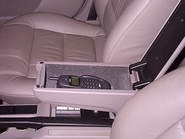
The following are the steps I took to integrate my Nokia 6160 Dual Band TDMA/AMPS cell phone and Nokia CARK-91 hands-free kit into my 1998.5 A4 2.8 Quattro with Bose/Concert sound system. My cellular phone is mounted in my armrest utilizing full integration with the factory sound system. I power my cell phone through switch & unswitched power routed to the RJ-45 connector underneath the armrest. My cell phone utilizes the factory installed microphone and speaker through my concert sound system. The telephone also automatically mutes my concert system when I receive or place a call.
I obtained the pin-outs from a Motorola technical manual for Motorola series II and III transceivers. Here is a list of the parts I used for my installation:
- Nokia CARK-91 hands-free kit
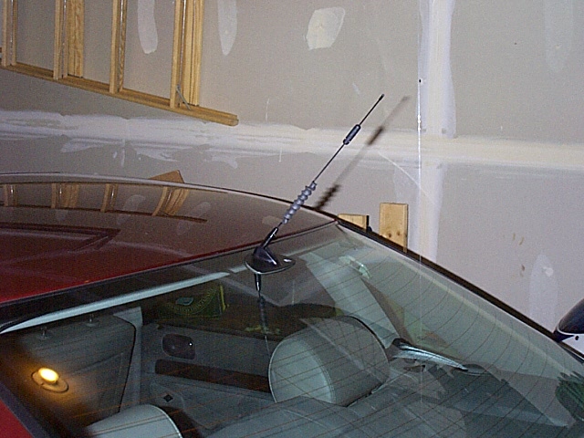
- AS Dual Band Cellular antenna 1900/900 MHz.
- Solder iron
- solder
- multi-meter
- shrink wrap tubing
- electrical tape
- Ethernet cable (RJ-45 connectors) 10 - 15'
- 1/8' stereo plug
- 1/32 stereo plug
- DB-25 connector (crimp type)
- DB-25 connector case
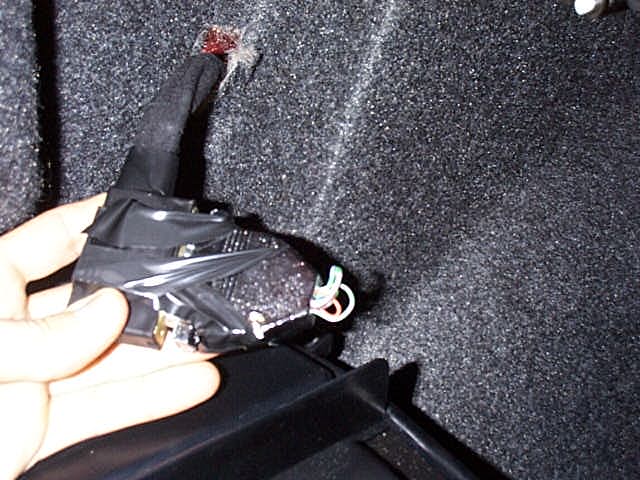
The RJ-45 connector that is located underneath your armrest does not have any direct connections to your cars systems or power. The RJ-45 connected run from the RJ-45 plug to pins on the DB-25 connector located behind the insulation on the drivers side of your trunk. Through certain pin connections I routed power, ground, speaker, mic, and radio mute connections to the RJ-45 pins. I installed the control box of my hands-free in my dash behind my glove box. All connections between the hands-free kit and the cars systems were made via the RJ-45 connector.
To make the connections on the DB-25 connector I used the thin wires that run in the Ethernet cable. You can cut one end of the Ethernet cable off since you only need one end. Take 1 foot of the Ethernet wires to make the connections on your DB-25 connector.
Here's the pins I used on the DB-25:
PIN # 3 Ground
Pin # 5 Switched 12V power
Pin # 10 Stereo mute
Pin # 14 Microphone -
Pin # 15 Microphone +
Pin # 16 Unswitched 12V power
Pin # 19 Speaker +
Pin # 25 Speaker -
I patched these pins to other pins on the DB-25
Pin # 23 (Pin 1 on RJ-45 plug)
Pin # 8 (Pin 2 on RJ-45 plug)
Pin # 11 (Pin 3 on RJ-45 plug)
Pin # 12 (Pin 4 on RJ-45 plug)
Pin # 18 (Pin 5 on RJ-45 plug)
Pin # 24 (Pin 6 on RJ-45 plug)
Pin # 1 (Pin 7 on RJ-45 plug)
Pin # 6 (Pin 8 on RJ-45 plug)
The following are connections I made on the DB-25
Connect Pin 3 to Pin 12 Ground to Pin 4 on RJ-45 plug
Connect Pin 5 to Pin 18 Switched 12V power to Pin 5 on RJ-45 plug
Connect Pin 10 to Pin 11 Stereo mute to Pin 3 on RJ-45 plug
Connect Pin 14 to Pin 8 Microphone - to Pin 2 on RJ-45 plug
Connect Pin 15 to Pin 1 Microphone + to Pin 7 on RJ-45 plug
Connect Pin 16 to Pin 24 Unswitched 12V power to Pin 6 on RJ-45 plug
Connect Pin 19 to Pin 6 Speaker + to Pin 8 on RJ-45 plug
Connect Pin 25 to Pin 23 Speaker - to Pin 1 on RJ-45 plug
You can then plug your Ethernet cable into your connector under the armrest and your ready to make your connections to your telephone control module. This particular Nokia model accepted the MIC and Speaker connections via Stereo jack. I wired the speaker connections on Ethernet cable to 1/8' stereo plug I purchased at Radio Shack (similar to connection of head phone on walkman) then wired mic to similar plug, but 1/32" in size. The rest of the power, ground and radio muting connections are self explanatory.
2000 model year information (contributed by Juan
Gomez)
I used the FAQ but made these changes. This schematic was true for my car a 2K A4 Avant 1.8t
with the Audi Symphony Radio. The only drawback is I could not find the
connection for the speaker. I asked the dealer and the speaker is in the phone that you would buy from them. This is also shown in the schematic. Besides the
speaker everything works great. Happy wiring!!!!
PUTTING IT TOGETHER: The signaling patch component The RJ-45 in the cabin has no connections to the car's systems This is
accomplished by patching the correct car system signal to the RJ-45 (which in turn is connected to the hands-free control module) via the DB25 connector that
is in the trunk. It's kind of like the old telephone days, when an operator used
patch cords to connect the proper people together. All you are doing is taking the
signal or power from one pin and routing it to another (the RJ-45 lines). This consists of 8 connections in a small area; you also have to patch in the fuses
here. First, take the male DB25 connector (I used the solder type) and solder a length of wire between the following pins:
PIN 17 and PIN 18 routes PIN 4 on the RJ-45 to the car's system ground.
PIN 5 and PIN 12 routes switched 12v power (for ignition sense) to PIN 5 on the RJ45. This will eventually connect to the BLUE wire on the hands-free
power harness. THIS CONNECTION MUST USE THE 1 AMP FUSE THAT COMES WITH THE CAR KIT.
PIN 10 and PIN 24 routes stereo mute in the cars system to PIN 3 on the RJ-45
connector. This eventually connects to the YELLOW wire on the hands-free
power harness.
PIN 14 and PIN 1 routes the mic negative on the pre-wired Audi piece on the
Sun Roof Control panel to PIN 2 on the RJ-45. This eventually connects to
the mic negative on the hands-free control module.
PIN 15 and PIN 8 routes the mic positive on the pre-wired Audi piece on the
Sun Roof Control panel to PIN 7 on the RJ-45. This eventually connects to
the mic positive on the hands-free control module.
PIN 4 and PIN 11 routes unswitched 12v power to PIN 6 on the RJ45. This
will eventually connect to the RED wire on the hands-free power harness. THIS CONNECTION MUST USE THE 2 AMP FUSE THAT COMES WITH
THE CAR KIT.
I could not find a suitable route for this I used the speaker that came with the
Hands free kit. PIN 6 and PIN 19 routes the speaker positive on the pre-wired Audi piece on the door (Bose systems) or to the stereo to PIN 8 on the
RJ-45. This eventually connects to the speaker positive on the hands-free control module.
I could not find a suitable route for this I used the speaker that came with the
Hands free kit. PIN 23 and PIN 25 routes the speaker negative on the pre-wired Audi piece on the door (Bose systems) or the stereo to PIN 1 on the
RJ-45. This eventually connects to the speaker negative on the hands-free control module.
Disclaimer: I don't except any responsibility of damage you may cause while trying to integrate your cellular telephone into your Audi automobile.
|