|
|
Introduction
The following article outlines my journey into the wonderful world of prying open a 30+K car. Two things to note concerning this article:
One more thing - I opened up the control module to take a look. DO NOT try to integrate the 61xx without it! There a LOT of
circuitry that apparently is required to make this work. Okay, with that out of the way, here's what I did.
The Goal
I wanted to use the pre-wired features that came with the car. More importantly, I didn't want the setup to look amateurish, of
retrofit -- it had to look like it was a system that was designed into the car. This meant that I was going to use all of the opportunities that presented themselves, from the standpoint of wiring and locations to place the hardware. I also did not want to make a single modification to the harness itself, ie. No cutting or splicing.
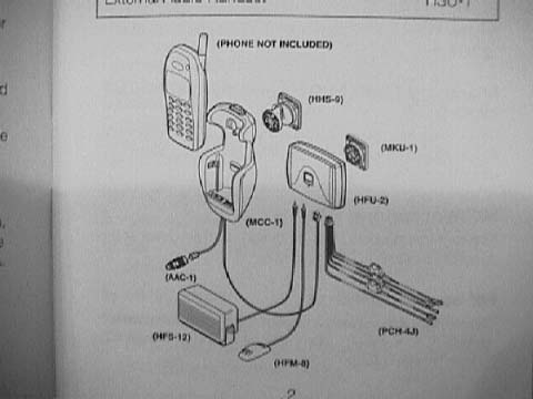
The Parts
I used the Nokia CARK-91H car kit as opposed to the CARK-91US, primarily for the privacy handset feature. In addition to the car kit, I used the following components:
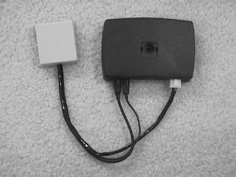
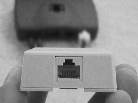
Now, as we take the wiring from the control module from the hands-free kit and tie them into the car system via the RJ45 jack box, we must make note of a) which pin is one on the jack, and b) which wires go to which pin. Holding the jack as shown in the photo, pin one is the leftmost one, and moves sequentially to the right (pin 8). We establish the following connections:
Now, pinout is important -- lines 7 and 8 are SHIELDED, therefore they are used for the speaker and mike connections. The RJ-45 coupler comes in a little later. You are now done with the cabin component for now. You simply take each wire from the control module and tighten it to the appropriate post inside the jack. To help prevent the wires from fraying, I tin each one to bind them with solder. Now, I know that cutting the wires on the speaker and mic may make you nervous, especially at the price the kit goes for, but its all very easy to do.
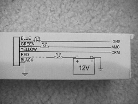
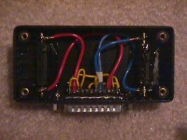
PIN 1 and PIN 15 routes the mic positive on the pre-wired Audi piece on the A-pillar to PIN 7 on the RJ-45. This eventually connects to the mic positive on the hands-free control module. PIN 16 and PIN 24 routes unswitched 12v power to PIN 6 on the RJ45. This will eventually connect to the RED wire on the hands-free power harness. THIS CONNECTION MUST USE THE 2 AMP FUSE THAT COMES WITH THE CAR KIT. PIN 6 and PIN 19 routes the speaker positive on the pre-wired Audi piece on the door (Bose systems) or to the stereo to PIN 8 on the RJ-45. This eventually connects to the speaker positive on the hands-free control module. PIN 23 and PIN 25 routes the speaker negative on the pre-wired Audi piece on the door (Bose systems) or the stereo to PIN 1 on the RJ-45. This eventually connects to the speaker negative on the hands-free control module. I made two slots in the top of the project case so the fuses could be accessed without opening up the case.This is optional. Make another opening for the DB25 connector. Attach the standoffs to secure the connector to the case. The cable will then connect to the project case. The serial cable was used so that I can connect one end to the DB25 connector that is in the trunk and route the box wherever I wanted without tearing up the trunk lining a second time. I then covered the wires and connections in two-part epoxy to minimize the possibility of vibration breaking a connection.
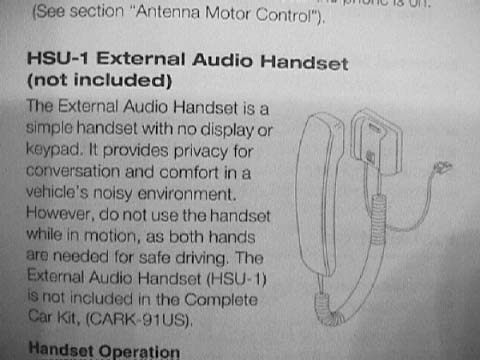
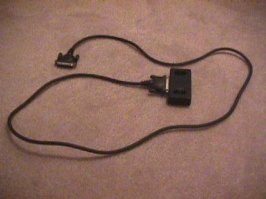
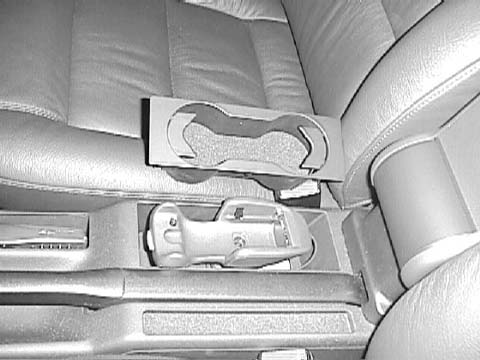
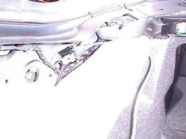
Now that the cradle has been located, I want to place the control module and RJ-45 box either under the dash on the hump forward of the lower vents (a lot of room there), or behind the glove compartment. I say want to; I haven't figured out how to get behind there yet. Perhaps someone can help me out with this in trade for this little journal. Anyway, with the module in the front, I took the main cable from the cradle, slid it between the carpet and the side of the console, and then ran the cable along side the console towards the front. I tucked it under the plastic console; there's a lot of room to do this without deforming the side. I then plugged it into the control module. The connector from the cradle looks like the RJ-45 plug on steroids. Now here's the interesting part. I UNPLUG the RJ-45 connector that is under the now vacated cupholder area. This takes the RJ-45 that is in the ARMREST BIN out of the loop. I then plug one of the RJ-45 patch cords into that connector under the cup holder area, route it along the same path as I did for the cradle cable and plug it into the RJ-45 jack. At this point, all of the wiring for the phone is now tied into the stereo and pre-wired parts! Now don't get too excited, because we still need to tie the system wiring into the RJ-45 bus. That is the magic of the DB-25 connector in the trunk. Before I get to the trunk, what about that connector that is left dangling under the spot where the cupholder used to be? AHHHH. Like I said, I hate to leave the installation looking amateurish. Well this is where the privacy set comes in. I take the OTHER RJ-45 patch cord, plug it into the female/female coupler, and attach it to the "dangling connector", route the cable along the same path as the other cables, and plug it into the remaining connector on the control module. That connector happens to be where the privacy handset would normally go. So what does this get you? Well, NOW YOU CAN PLUG THE PRIVACY HANDSET INTO THE JACK IN THE ARMREST BIN! No dangling cables! When the armrest is in the up position, your rear passengers can use the phone in the bin!
THE FINISHING TOUCHES The photos included in this article show the fundementals of the installation They do not reflect how I made the final touches that made the installation look OEM. Other than shortening the privacy handset cord and attaching a new RJ-45 connector to the end, the only other area that needs attention is the area under the cradle. That area is pretty unsightly. There are several options. Since I'm an architect, I had a Product Rep craft a piece of stainless steel with a swirled finish. The dimensions at the bottom are 7 1/16" by 2 ¾". The other option is to take a piece of carpet and attach it to some sort of stiff backing that can take the screws from the cradle base. In the end though you may want to go to your Audi dealer and order part 8D0-863-301-J-1EJ. It seems there has been over the years a number of variations of inserts for this cavity, one of them simply a bottom liner with the flecked pseudo carpet! Well, that's perfect. Just screw it and the cradle base down, make a slot for the cables from the cradle to the area under the lining, and it looks OEM. Oh yeah. Don't forget to tell them the color of your interior Well, that concludes most of my experience. I hope you all find it helpful, entertaining, and perhaps even fun. If you have a different phone than the Nokia, the fundamentals are here; it shouldn't be too difficult to make the appropriate modifications. Happy motoring!!!
|
|
Advertising |
Contact Us |
Cookie Policy |
Privacy Statement |
Terms of Service |
Do Not Sell My Personal Information
© 2020 MH Sub I, LLC dba Internet Brands |