| Tech Article Title
|
Author
|
Date
|
| Integrating a Nokia 6160 Cell Phone ('00 model)
|
ed@palisoc.net
|
1999
|
 |
| |
|
Introduction
|
| This document
is broken into two main sections, the first reviews the concepts and information
that was used to develop the approach to making the interface box for handsfree
car kits. The second part describes in detail the particular approach the
author took in making an interface box to work with the Nokia handfree carkit
for the 51xx and 61xx series cell phones. I reused some photos from my installation
into my old 1999.0 2.8, so please ignore any interior discrepancies you
see. |
| |
| Contents |
| |
Part
One: |
|
| |
- Disclaimer
- Overview
- Tools
- Parts
- The optional circuit
- The Interface Box
- Additional Steps
specific to the Nokia handsfree carkit
|
|
| |
Part
Two: |
|
| |
- Construction Summary:
The major parts of the project
- Building the Interface
Box
- Installation
|
|
| |
Appendix |
|
|
| Disclaimer: |
| |
The reader assumes
all liability and risk associated with using the information contained
in this document.
The information is
based on sources that were assumed to be accurate at the time this document
was written, apply to the specific needs of the author, and are tailored
to the particular A4 used in the article. Every effort has been made to
describe the intent of each step so that the information may be interpolated
for use with other model years, vehicle options, and different handsfree
kits; however, the author cannot anticipate every possible permutation
that readers may encounter. The reader should research any specific issue
that may modify the information in this document.
|
| |
| Overview |
| |
The
author's car, used for this installation, is a 2000 A4 1.8t with the following
options:
- Convenience package
- Sport package
- Quattro
- Bose system with
CD changer
- Head restraint
system
|
| |
I wanted to use the
pre-wired features that came with the car. More importantly, the final
installation had to look like it was factory installed. This meant that
I was NOT going to muck around with the wiring harness and start splicing
and cutting just to make the installation work. If there was not a way
to use the connectors as is, I was not going to attempt this project.
That may make some folks out there breath easier come time to sell or
return the leased car. In addition, if the reader would want to change
the cell phone in the future, the modular approach taken here, would facilitate
the changeover.
The car kit installed
by the author was the Nokia CARK-91H handsfree carkit for use with a 6120
(51xx and 61xx series). For those with other phones or brands, refer
to the appendix for further information.
The Audi has the
advantage of having integrated support for handsfree operation. This in
large part because Audi offers as an option a cellular telephone. Audi
has integrated the speaker output, microphone input, and stereo muting
during active handsfree operation into the car's systems; the stereo and
trip computer both display "PHONE" during use. Most
handsfree car kits that require "professional" installation have the same
requirements, namely:
- Unswitched 12
volt positive
- Switched 12 volt
signal
- Negative ground
- Speaker output
- Microphone input
Some kits such as
the Nokia support stereo muting; this is standardized as a ground sensing
circuit. To work, a stereo headunit that supports this mutes when a signal
wire is grounded; a handsfree carkit that supports this feature will ground
a signal wire when a call is connected. Kits may provide other features,
but for the Audi, they are largely unnecessary and therefore unused for
the purposes of this document.
Because of the limited
number of electrical requirements, most any carkit can be made to work.
Audi provides a standard DB25 connector in the trunk on the driver's side
for the OEM cell phone. The pinout for this connector is as follows:
- 1. Pin 7 of the
RJ-45 in the armrest
- 2. N/C
- 3. Ground
- 4. Unswitched 12
volts
- 5. Switched 12
volts
- 6. Pin 8 of the
RJ-45 in the armrest
- 7. N/C
- 8. Pin 2 of the
RJ-45 in the armrest
- 9. N/C
- 10. STEREO MUTE
- 11. Pin 3 of the
RJ-45 in the armrest
- 12. Pin 4 of the
RJ-45 in the armrest
- 13. N/C
- 14. Microphone
(-)
- 15. Microphone
(+)
- 16. Unswitched
12 volts
- 17. Ground
- 18. Pin 5 of the
RJ-45 in the armrest
- 19. Speaker (+)
- 20. Microphone
shield
- 21. N/C
- 22. N/C
- 23. Pin 1 of the
RJ-45 in the armrest.
- 24. Pin 6 of the
RJ-45 in the armrest
- 25. Speaker (-)
As you can see, this
connector is extremely versatile; the wiring is direct and does not interface
with any critical elecronic systems other than than incidental connections
to the radio. It should also be fairly obvious how the connector can be
utilized to integrate a handsfree kit into the car.
One additional item
featured in this document is a means of adjusting the Audi microphone
output to match the car kit microphone input requirements. The Audi microphone
has a built-in preamp that overdrives most kits. The circuit described
in this document is optional; the microphone in the headliner can be switched
out with the microphone that comes with the carkit, but this limits you
from changing phones in the future. The rest is fairly straight forward
wiring.
Those not interested
in a handsfree kit can use this pinout information to redirect signals
or power into the connector in the armrest; remember that the wiring to
the armrest is direct and does not pass thru any critical systems. To
put it in the most basic terms, to make the handsfree kit work, you are
marrying the power and signal requirements of the carkit with the power
and signals available thru the DB25 connector via an interface box.
|
 |
| |
| Tools |
| |
The following list
outlines the tools I used in conjunction with this project:
PC Board (optional,
see following sections)
- PC acid etchant
- PC Resist decals
- Cordless dremel
tool
- Various size drill
bits
- Dremel cutting
wheel
- Soldering iron
- Rosin core solder
- Rosin flux
Interface Box
- Cordless dremel
tool
- Various size drill
bits
- Dremel cutting
wheel
- 3/4" Power drill
- Wire cutters
- Wire strippers
Car Interior Installation
- Phillips head screwdriver
- Rachet driver &
extender
- 8mm socket
- 10mm socket
|
| |
| Parts |
| |
This section and others
to follow are broken into 2 levels of complexity and parts requirements:
BASIC -
Minimum parts required
ADVANCED
- Basic plus tunable microphone input, convenience components, and privacy
handset in armrest. For manual muting switch, or powered connector in
armrest for other gadgets, refer to the appendix.
|
| |
| |
Basic
parts requirements |
|
| |
Carkit.
The author used a
CARK91-H Nokia handsfree carkit that includes:
- Control module
- Cradle with antenna
and main data connector
- External speaker
- Eexternal microphone
- Otional handset
(see below)
- Power harness
- Several mounting
pads and miscellaneous screws
|
 |
| |
DB25 male/female
STRAIGHT THRU cable.
Length is dependent
on placement of interface box; this placement will be determined by wiring
length limitations of the handsfree carkit. The author located everything
under the rear seat - 6'-0" was sufficient. The picture shows the unfinished
interface box attached to the end.
|
 |
| |
DB25 male connector.
The author used the
solder type, but a crimp type is also available.
|
 |
| |
Project box.
The author used one
from Radio Shack measuring 3"x2"x1", but use whatever size fits and you
feel comfortable with.
|
|
| |
1 & 2 amp fuses
and holders
Only if they were
NOT included with the carkit.
|
|
| |
|
|
| |
Advanced
parts requirements |
|
| |
In addition to the
basic requirements, there are author specific approaches that are outlined
in this section; the parts listed here are for the optional circuit.
Single sided copper
coated PC board (optional - circuit and/or the use of a PC board is the
discretion of the reader.)
- One 10uf capacitor.
- One 1uf capacitor.
- One 10k ohm resistor.
- One 50k potentiometer.
- Optional two 1
amp thermal circuit breakers to replace the 1 amp fuses
- Optional one mini
2 amp fuse and holder to replace the 2 amp fuse
- RJ45 8-pin patch
cord (for tying in the privacy handset connection to the armrest)
The following is complete
parts list the author ordered from www.mouser.com
|
 |
| |
PART |
QTY
|
DESCRIPTION |
|
| |
ME442-76-0100 |
2
|
MOUSER
FUSE CIRC.BRKR 250VAC 1A |
|
| |
5768-53007 |
1
|
LITTELFUSE
FUSEHOLDER PCB HORIZONTAL |
|
| |
5768-97002 |
1
|
LITTELFUSE
AUTO FUSE MINI FUSE 2 AMPS |
|
| |
72-T70YP-50k |
1
|
DALE
SINGLE-TURN TRIMMER 1/4" SQ V/ADJ 50K |
|
| |
ME271-10k |
1
|
XICON
1/4W 1% METAL FILM RESISTOR |
|
| |
571-7479122 |
1
|
AMP
AMPLIMITE D-SUB 25P PLUG TIN |
|
| |
140-LLRL50V10 |
1
|
XICON
LOW-LEAKAGE RADIAL ELECTROLYTIC CAPACITOR |
|
| |
140-LLRL50V1.0 |
1
|
XICON
LOW-LEAKAGE RADIAL ELECTROLYTIC CAPACITOR |
|
| |
571-13809360 |
1
|
AMP
MINIATURE CONNECTOR |
|
| |
|
|
| The
Optional Circuit |
|
| |
As stated before,
the Audi microphone has an integrated preamp circuit that boosts the level
of output. In addition, the Audi microphone expects a line level voltage
of 12 volts.
The green wire
of the nokia kit supplies 12 volts and is meant to operate a motorized
antenna; it can source 300 ma. The unique feature of this wire is that
it only supplies the voltage when the phone is in the cradle and has been
turned on. This wire is protected by the 1 amp fuse or circuit breaker.
If you are using
a carkit other than the Nokia, you can substitute a connection from pin
5 of the DB25 to supply SWITCHED 12 volts from the car.
This voltage, via
the 10k ohm resistor, provides the necessary line level to the Audi microphone
via pin 15 of the DB25. The DC voltage is decoupled and isolated from
the circuit by using a 10uf capacitor with the positive lead connected
to pin 15. The negative lead of the capacitor connects to one end of the
50k potentiometer. The other end is connected to qround (pin 3). The Nokia
microphone positive input is connected to the middle post of the potentiometer,
allowing for variable adjustment of input level. To ensure that all voltage
is decoupled from the carkit, an additional 1uf capacitor is used between
the potentiometer and Nokia input; the negative lead connected to the
potentiometer post.
This circuit is
optional; you can eliminate it and connect the carkit microphone
positive wire directly to pin 15 of the DB25 if you solder the carkit
microphone in place of the Audi microphone. You also don't have to use
a PC board. A bread board, or even no board need be used if you isolate
the components from each other.
|
 |
| |
|
|
| The
Interface Box |
| |
Basic
Approach |
|
| |
This will accommodate
most carkits. Here is a quick summary of the necessary connections made
inside the interface box to the male DB25 of the interface box. The color
of the following wires refer to the Nokia carkit power harness. Interpet
as necessary if you are not using the nokia carkit.
- Red - Unswitched
12 volts. Connects to pin 16 on the DB25. This provides power to
the carkit. Isolate with the 2 amp fuse.
- Blue - Switched
12 volts. Connects to pin 5 on the DB25. This provides the carkit
with a means to determine when the car is turned off. Isolate with a
1 amp fuse.
- Black - Ground.
Connects to pin 3 on the DB25. Self explanatory
- Speaker positive
(red)
- Connects to pin 19 on the DB25.
- Speaker negative
(black)
- Connects to pin 25 on the DB25.
- Microphone positive
(red)
- Connects to pin 15 on the DB25. See section on the optional circuit
that I installed between the microphone wire and pin 15.
- Microphone negative(bare
copper) - Connects to pin 14 on the DB25. I used heat shrink tubing
to protect the wire.
The green wire
is used in the optional circuit to provide 12 volt line levels.
|
 |
| |
Additional
Steps Specific To The Nokia, non Nokia Stereo Muting, and armrest power.
|
| |
Privacy Handset/Data
connector
The privacy handset
uses the same connector as the one in the armrest. To this end, the connections
are straightforward. An RJ45 patch cord is used with a connector at one
end that plugs into the handsfree control module, the other end wired
into the interface box as follows:
- Wire for pin
1 of the Nokia connector - goes to pin 6 of the DB25
- Wire for pin
2 of the Nokia connector - goes to pin 1 of the DB25
- Wire for pin
3 of the Nokia connector - goes to pin 24 of the DB25
- Wire for pin
4 of the Nokia connector - goes to pin 18 of the DB25
- Wire for pin
5 of the Nokia connector - goes to pin 12 of the DB25
- Wire for pin
6 of the Nokia connector - goes to pin 11 of the DB25
- Wire for pin
7 of the Nokia connector - goes to pin 8 of the DB25
- Wire for pin
8 of the Nokia connector - goes to pin 23 of the DB25
NOW THIS IS VERY
IMPORTANT! Either Audi or Nokia uses an inverted pinout. To compensate,
and for the purposes of the connections listed above, I consider the
RIGHTMOST pin of the connector ON THE NOKIA CONTROL MODULE to be pin 1.
Make sure you properly
trace the correct wire that CONTACTS the RIGHTMOST pin of
the Nokia connector ON the CONTROL MODULE to pin 6 of the DB25.
Failure to properly wire these connections will result in the carkit not
functioning correctly.
|
  |
| |
Nokia
Stereo Muting |
| |
The Nokia carkit supports
stereo muting. Again, the color of the following wires refer to the Nokia
carkit power harness. Interpet as necessary if you are not using the nokia
carkit:
- Yellow - Stereo
mute. Connects to pin 10 on the DB25
|
|
| |
Non
Nokia Stereo Muting |
| |
For kits that do
not support this feature, it is possible to implement its equivelent in
two ways:
- Use a third party
mute device. These work by sensing current drain when the phone is in
use, and then provide the grounding necessary to activate the mute feature
in the radio. I am aware of one available at autotoys.com
- Wire a manual push
button to activate stereo muting. One possible approach to do this is
to take advantage of the connector in the armrest.There
is also a connector UNDER the center console that ties the armrest to
the car. Either one can be used. Simply wire one RJ45 pin to pin 3 of
the DB25 to provide ground, and another RJ45 pin to pin 10 of the DB25
to provide stereo muting. To provide MANUAL stereo muting, wire these
two RJ45 pins via cable and connector to an on/off switch to complete
the circuit when needed. You can perhaps wire this into a replacement
for one of the dummy switches on the center dash. This can only be done
if the RJ45 in the armrest is not being used for anything else, such
as the privacy handset connection described above. At this point, you
can also take the opportunity to use the RJ45 as a power source. DO
NOT do this without using a 1 amp fuse, as the gauge of wiring used
is very small.
Example of mute switch:
Connect pin 23 to pin 10 of the DB25. Connect pin 8 to pin 3 or pin 17
of the DB25.
|
|
| |
|
|
|
Construction
Summary: The major parts of the project
|
|
Carkit
The CARK91-H/US is pictured. |
|
|
Interface
Box and 25-pin STRAIGHT-THRU Cable. I got my cable at CompUSA. |
 |
| |
Antenna: includes:
- Antenna mast
- coupler repeater
box
- 10 feet of coax
with a mini-uhf connector
A glass mount antenna
acts as a conduit enhancing the signal flow in and out of the car. Just
mount the antenna mast to the outside of the car windshield with the doublestick
tape then mount the "repeater box" on the opposite side of the windshield.
No hole drilling through the windshield required. Too many options. I
am looking into a patch antenna or a bumper antenna for a more stealthy
look. i might even cut the connecting post on the cradle so the atnenna
won't deactivate when I put the phone into the cradle.
|
  |
| |
|
|
| Building
the Interface Box |
|
| |
Start by preparing
the wires from the control box. I cut the wires to about 10 inches.The
wires and connectors from right to left are:
Power harness:
3x2 molex connector includes unswitched 12v (red), switched 12v (blue),
ground (black), stereo mute (yellow), 12v aux supply (green).
Privacy handset/data
port: RJ45 8 pin wiring. I used a CAT5 network patch cord for this.
It does NOT come with the handsfree kit.
Microphone connector:
2 wire positive and negative. negative is bare copper that must be protected
using shrink tube or similar.
Speaker connector:
2 wire positive and negative. Red is positive, black is negative.
|
 |
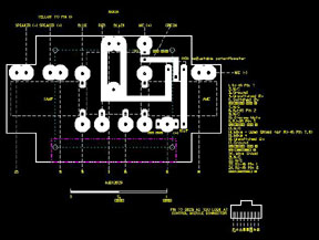
| |
The wiring
diagram is illustrated on the right. Review the Interface Box overview above
for the specific wiring to the DB25. |
|
| |
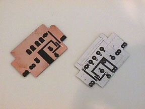
The PC board
method |
|
| |
Make
an accurate image of the PC board by print or copy. This is then temporarily
glued to the fiberglass side of the PC board, NOT the copper side. Next,
drill the holes for the components thru the board, so you can locate the
positions of the parts. You then use the holes to lay out the copper pattern
using the resist decals.
|
 |
 |
| |
Once the
pattern is laid out, you then remove the unwanted copper in a bath of copper
etching solution. Clean the copper trace. |
 |
| |
Make sure
the PC board you have just made fits the project box. Your application may
vary from the pictures, depending on the box you chose. The image pictured
shows the board in the box, copper side DOWN. At this time, you want to
make the openings for the wires that need to come into the box, and the
hole for the DB25. Thsi way you can remove the board while you cut and not
ruin the board in the process. |
 |
| |
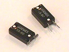
The first
part to install on the board are the thermal circuitbreakers. These work
by tripping when the amperage is exceeded or you short out a connection.
They work much like the ones in your breaker box at home, but these reset
themselves after a couple of minutes. They may trip as you solder them,
as the heat from the soldering iron will trip them. The upper right breaker
is how they come. The lower left is how I modify it prior to installing
them. I bend the thicker base out flat, then bend the thinner leg back on
itself, leaving a gap. This gap is used in the next step, to make a way
to solder on a wire to then connect to the board. One tip - lightly sand
the legs before you bend them, so that soldering is easier. |
 |
| |
Next,
use some epoxy to glue the breakers onto the fiberglass side of the board.
Notice that the gap in the bent legs align with the holes in the board.
Take some wire - I used the excess legs from the trimmed 10k ohm resister
- and make shepards hooks.
I then ran it thru the gap into and thru the hole in the circuit board.
I then soldered the wire to the legs of the breaker, and the wire to the
board. Make sure that the solder doesn't get excessive between the breakers,
since the 2 amp fuse fits in that space. |
 |
 |
| |
Install the 10k ohm
resistor, the adjustable potentiometer (blue square component in image),
and capacitors onto the board and solder them.
CRITICAL NOTE: The
positive/negative orientation of the capacitors are very important. Both
the 10uf and 1 uf capacitors has the NEGATIVE lead going to the potentiometer.
The POSITIVE leads go to the wires leading away from the circuit board.
|
 |
| |
Next, install
the mini fuse holder. Here is a picture of the completed circuit board.
The fuseholder has a somewhat large center post. Make suer the hole is large
enough for it to pass thru, and don't force it. |
 |
| |
From then
on, it's straight forward wiring and soldering. Here's a shot of the box
in progress. Tip - start by soldering the wires from the control module
first, otherwise you'll have a tough time getting behind to the backside
of the board to solder the remaining wires. Use the schematic and wiring
information presented earlier in the document. |
 |
| |
A
little tight, I know. You will adjust the microphone input by turning the
potentiometer to suit your taste. The wiring that I did, has most of the
wires going to the board, then from the board to the male DB25 connector.
The eception to this is the 8 wires for the armrest. I soldered them directly
without first running to the PC board. Remember, you do not need to use
a box this small. YOu may want to try out others. |
 |
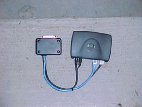
| |
Here's
a picture of the final interface connected to the control module |
|
| |
Installing
into the Car |
|
| |
I ran the cables from
the handsfree cradle under the carpet along the side of the drive tunnel,
and pulled it through the hole pictured on the right.
I then ran the DB25
cable behind the trunk trim on the drivers side, behind the rear passenger's
bolster, into the rear seat area. The bolster easily unclips. I used the
existing cable ties to neaten up the wiring.
|
  |
| |
For the cradle, I
ordered stock Audi trim pieces that fit in the same space as the cupholder
did. For onyx interiors the part number is:
8D0 863 301 J 1EJ
For opal grey, the
part number is:
8D0 863 301 J 3PF
As you can see, the
last four digits identify the interior color. I then epoxied this piece,
which is a bit flimsy, to a stiff material, in my case a pice of steel.
The plastic part is covered in carpet fleck, but is too weak to handle
a cradle base. Notice the cutout that leaves room for the cable to get
by the plate, so it can go under into the center console.
|
 |
| |
Removing the center
console is easy. Unbolt the armrest. You can see the three bolts when
you undo the rear ashtray, and the cupholder. Then unscrew the two bolts
that are under plastic covers right by the shift. Finally, undo the emergency
brake handle and boot by simply sticking a small flathead screwdriver
as pictured, and pulling out the plug. The covers then slide right off.
You also need to pull up on the shift boot to losen the front edge of
the center console.
You also need to undo
the small plastic cover at the back of the front seat slide rail. pop
off the cover with the small screwdriver, and undo the screw. CAREFUL!
It strips easily, so don't force it or overtighten when you place it back.
|
   |
| |
With everything
undone, it is very easy to lift the carpet to run the wires under it. I
could stick my arm in there. One thing to look out for. Make sure the cables
from the cradle pass BEHIND the emergency brake connector. If you goofed,
you don't need to pull the calbes, just undo the connector, move the cables
then reattach the connector again. |
 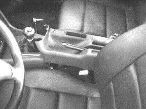  |
| |
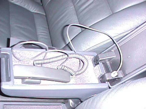
This is
what the final installation looks like. |
  |
| |
The antenna.
No need to go into detail here.There are too many options to go over, so
you need to research this one yourself. Suffice to say, there is room between
the headliner and glass to push the coax into it. The TSB for the OEM Audi
install says to do just that. |
|
| |
|
|
| APPENDIX |
|
| |
This section
is done as a mini-FAQ. I hope it covers most of the questions I've seen
on Ausiworld over the last year or so... |
| |
Can I use a carkit
other than the nokia?
Sure can. It may
not support the stereo muting feature on it's own, but you can either
use a third party device, or make a manual pushbutton that will perform
the same function. See the information above.
|
|
| |
I don't have a
Bose system. What's the difference in how to implement the handsfree kit?
The Bose system
has a dedicated speaker, but is still controlled by the radio. This means
that if the radio DOES NOT MUTE, the speaker is dead. When the mute is
activated, the speaker output can be heard.
For the NON-BOSE,
the speaker output is routed thru the radio, and is user selectable from
the right to left front speakers. This is done by the controls on the
radio. Read the manual on how to do this.
Other than that,
the wiring is IDENTICAL from the perspective of this interface box.
|
|
| |
I can't solder.
Can I still do this FAQ?
No. Hire a pro,
and give them this info. It may cost you though.
|
|
| |
What if I don't
want to mount the cradle where you show it. What do I need to know and/or
do?
The limitation
is the length of the cable from the cradle. If you locate it too far,
it won't reach into the rear seat area. In this case, get a longer DB25
cable, and place the interface box in the front area. This will give you
alot of options for the cradle. You'll just have to run the DB25 cable
a longer way, that's all.
|
|
| |
If I wire the armrest
for power, and NOT the privacy handset, or I am not doing the carkit,
but am interested in the connector, what can I do with the 8-pin connector
in there?
There is alot you
can do with power in the armrest. Yu can supply power to the pins so you
can pull power to a G-Tech, radar detector, you name it. It doesn't have
to be power. You can wire a video recorder in the trunk, and use the wiring
to tie the board camera into the cabin. Plug and play. Personally I like
the idea of a power source and a manual mute button. This way I can mute
the radio, and unmute it without changing the volume.
|
|
|