Once removed from the dash, the compartment was disassembled into the box, door front, and door back. The back of the door was discarded and replaced with the front panel PCB. I decided to re-use the latch button to retain a factory appearance.
This servo is designed for use in model aircraft to raise and lower the landing gear. It travels 180 degrees, has lots of torque, and it's nice and small. No, it's not terribly heavy, but there is some friction to overcome, plus the arm has a large radius of about 1.5" to provide the needed 3" of travel. RC servos typically aren't that powerful and are usually used with shorter servo arms.
Here you can see the guts of the motorized drawer including the installed retract servo. The sides were fabricated from black UHMW. A slot at the base rides on the chassis plate. A plastic piece was cut away from the rest of the original storage compartment box. The simple arm and slot mechanism has two nice features for this application. First, linear speed is slowed at the ends of the travel. Second, it essentially locks the drawer when open, so pushing on it won't cause it to slide back in. The chassis is constructed of 1/8" 6061 aluminum plate that also serves as part of the slide mechanism.
I took apart a spare Firewire cable and salvaged the dock connector (unfortunately you can't just pick these connectors up at your local Radio Shack).
Here's the dock connector mounted on the PCB. The connector wasn't designed for PC mounting, so it was pushed through a slot in the board and then soldered in place on the top side.
With the dock connector mounted on the board, small jumper wires were used to connect the pads to the tiny pins on the connector. (1)Audio line in out, including a floating signal ground. Using the separate signal ground instead of the vehicle's chassis ground helps to reduce hum and alternator whine.(2)+12V supply to power and charge the iPod. The iPod includes an internal regulator that can handle 8-30v, so powering it directly with the vehicle's 12v supply is fine.(3)The Firewire TX pin sends out 3v even when the iPod is asleep. It's used to control the audio relay and for the interlock feature.(4)Ground
A little black paint and some rubber feet complete the connector board.
This piece of UHMW (Ultra-High Molecular Weight Polyethylene) was machined with a router table to provide a snug fit for the iPod; the clearances are just enough to allow the iPod to slide freely in and out.
Here's the dock base with the PCB mounted on the underside. The holes in the corners of the board were drilled slightly larger than the screws to provide a little wiggle room. With the screws still loose, the iPod was inserted to precisely align the dock connector, and the screws were then tightened.
A little metal polish and a piece of terrycloth on an orbital sander turned the 6061 aluminum into a thing of beauty!
The finished dock assembly looking all spiffy. And yes, I did polish the screws too.
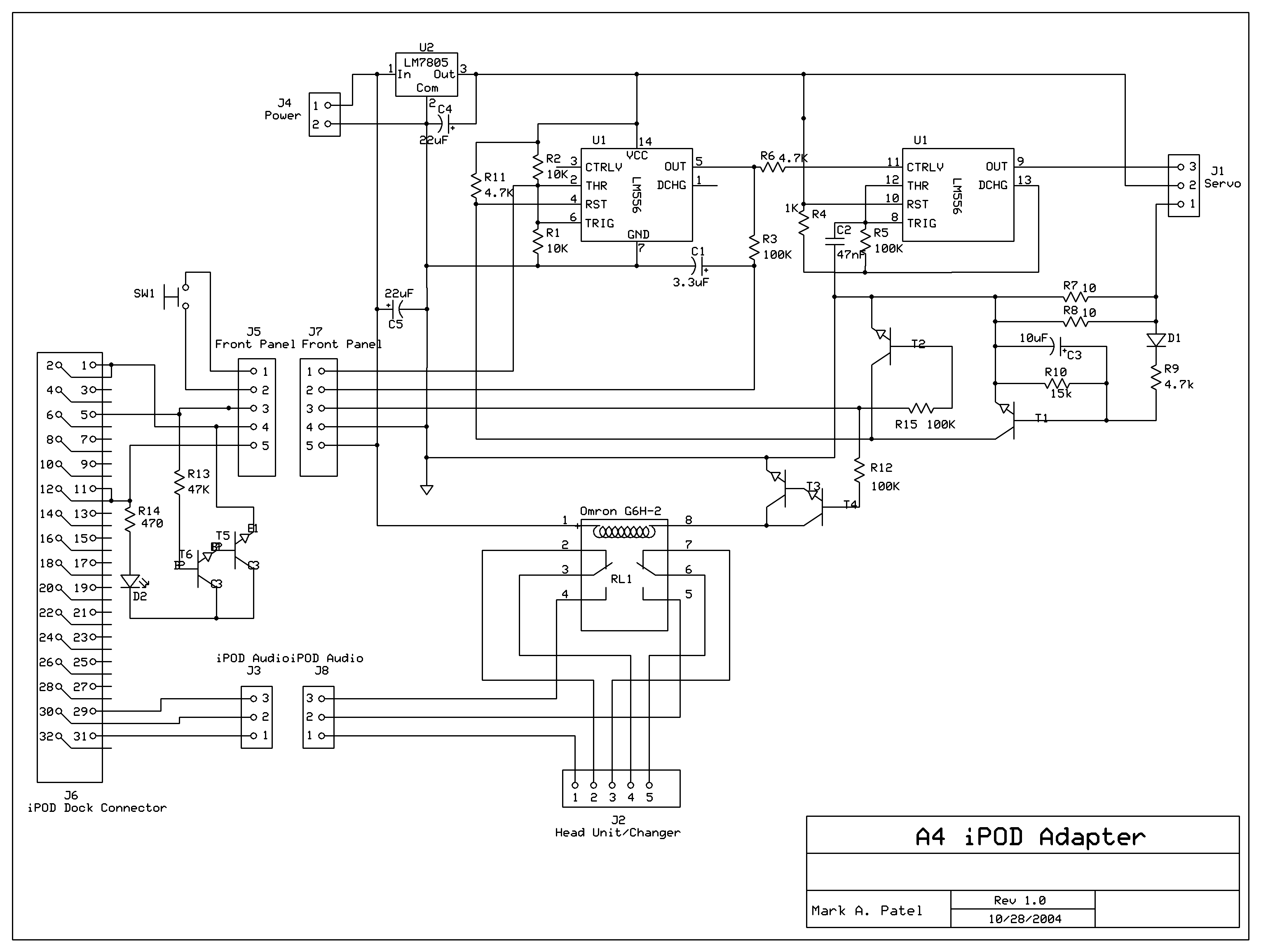
The main PCB includes a signal relay to switch the CD changer's audio lines and control circuitry to open and close the drawer. (1) DPDT signal relay switches between the CD changer and the iPOD's line out signal.(2)A single LM556 dual timer IC provides the state control and also generates a PWM signal to drive the servo.(3)A 7805 regulator provides a constant 5v supply for the control circuit and servo, and also isolates it from voltage fluctuations during engine starts.
This is the front panel PCB that was mounted behind the original compartment door front. The small SPST switch is positioned exactly where the mechanical latch mechanism was so the original OEM plastic button could be used.
Here's the front PCB mounted on the end of the drawer. The mounting holes are oversized to allow fine tuning of the fit (there's not much clearance with the surrounding dash facia).
The front cover was part of the original compartment door and required some minor modidications for its new role. Some plastic around the button opening needed to removed to accomodate the SPST switch on the PCB. Small UHMW blocks were glued on to secure the cover to the front panel PCB. A small hole was added for the status LED.
This is the harness that connects the CD changer to the head unit. The red and white wires are the audio lines that have been cut and stripped.
I used a spare USB extension cable to complete the harness. USB connectors have 4 conductors plus a shield, so it's perfect for handling the line level audio in/out.
In the closed position, it looks like a stock A4 dashboard (except for the tiny LED next to the open/close button)
Press the button, and it extends out of the dashboard in about two seconds. Pressing the button will close the drawer. Jam detection circuitry was used to sense an obstruction while closing the drawer; it automatically reverses if it senses too much resistance. The iPOD is easily inserted into the adapter. The precise fit and dock connector make a secure mounting that has yet to come loose on even the bumpiest roads. The LED lights to indicate that the iPod is fully inserted. Pressing the close button does nothing if the iPod is present to prevent damage.
Artwork for the main PCB (component side view)
Below is a small version of the Schematic. Hover your mouse over varous areas to get a breakdown of that area's function.


