| Tech Article Title |
Author |
Date
|
| OEM Power Rear Sunshade Install |
Boston Driver |
2006 |
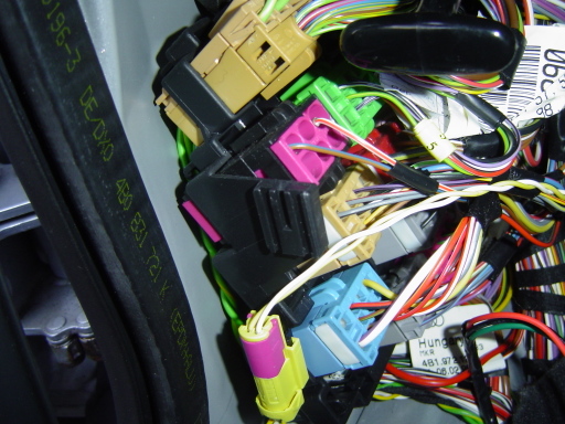
First, you have to find one of these wiring harnesses...
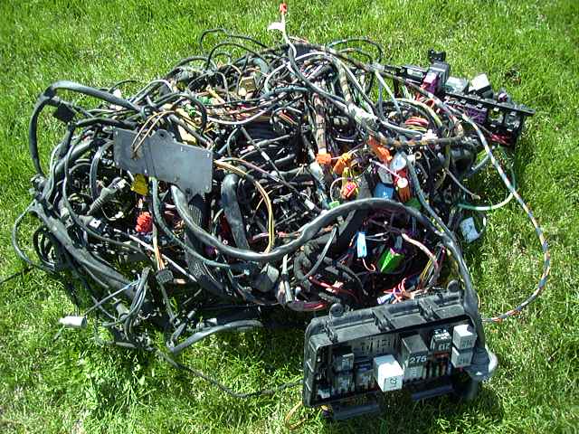
Just kidding!!!
The install is not too complicated, but at times, I felt like I was dealing with that mess above. The reason this isntall was at all time-consuming was mostly because of the number of interior trim pieces that have to be removed to do this installation. Of course, it is well worth the time and effort to DIY if you can source a rear shelf with the sunshade already in it. Separately, the components are quite expensive.
I did my install in stages, since I swapped out the non-shade shelf from my 2002 4.2 for the rear shelf with the sunshade from my 2001 2.7T, so at first, the priority was to get the rear shelf properly installed in the 2.7T that was for sale. I also ripped out the various wire connectors from the old car so I could reuse them in the 4.2.
Okay, the install write-up here is broken down into the following stages:
1) Removing the C/D-pillar trim and rear seat
2) Removing the rear shelf
3) Pre-wiring for the sunshade
4) Installing the new shelf
5) Running wiring to the lower A-pillar
6) Switch installation and final wiring
Parts required:
Rear Shelf (98-01) [4B5 863 411 AS 6PP]
Rear Shelf (02-04) [4B5 863 411 AR 7H8]
(Note: not sure why the part numbers for the rear shelf are that different, but for what it is worth, I installed my 2001 2.7T rear shelf into my 2002 4.2)
Sunshade [4B5 861 329 MSE]
Motor [4B0 969 733]
Control Unit [441 907 491 A]
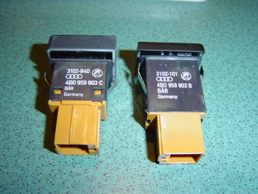
Dash Switch (98-01) [4B0 969 903 B]
Dash Switch (02-04) [4B0 969 903 C]
Connectors [various part numbers to be updated later once I get home to ETKA]
Wire AWG 18 and AWG 22
In-line wiretaps
Button-style wiretaps
Tools required
T-25 torx driver
Pliers
Wire cutters
Radio removal tools
1) Removing the C/D-pillar trim and rear seat
The rear shelf is anchored to the car with simple metal clips on the front edge and underneath the rear shelf and two very large hooks on the side. Sounds easy, right? Well, not so easy, since those two hooks on the side are hidden under the C/D-pillar trim. In addition, the out-board seatbelts run through holes in the rear shelf, and the lower anchor points must be released to feed the belts through the holes for removal. So, this stage requires removal of the C/D-pillar trim and the rear seats. I will cover the rear seatbelt removal in the next section.
D-pillar trim removal
You have to remove D-pillar trim, which spans from the B-pillar to the lower corner of the rear window.
Remove the little "AIRBAG" trim on the upper B-pillar trim to reveal a T-25 torx bolt that has to be removed.

Then, remove the coat hanger. With the coat hanger pivoted to the open position, use a philips head screwdriver to remove the screw.

Now remove the coat hanger block to reveal another T-25 torx bolt. Remove that bolt.
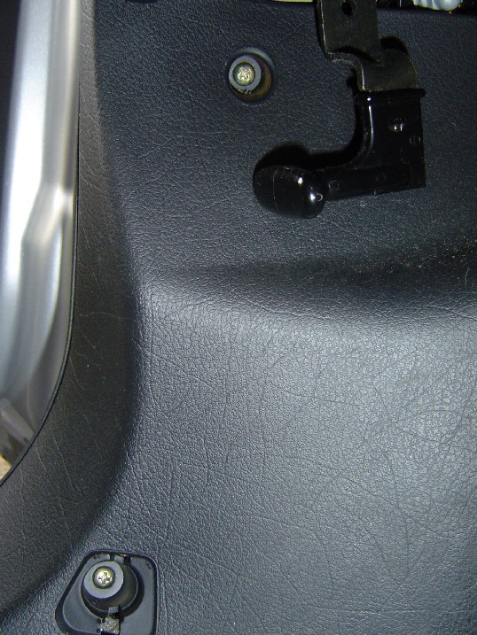
Remove the rear grab handles by removing the T-25 torx bolts hidden under the square caps that you can see when the handle is down. Just use a thin screwdriver to open those caps, and you will see the two bolts hidden under there.

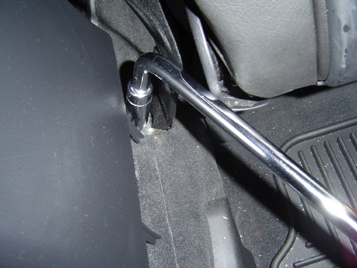
Then, Looking at the rearward grab handle hole, you will see a brass colored washer.

Grab that with some pliers, and pull hard toward the front of the car. You should feel it pop.

Then just pull the trim away from the car frame, toward the center of the car, to release the single metal clips located just below/rearward of the clip you release with the cable. This picture below shows the clip that was released with the cable glued to the brass washer. Using pliers, remove that from the slot in the car's frame so you can reinstall it in the D-pillar trim.
C/D-pillar trim removal
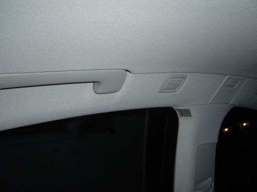
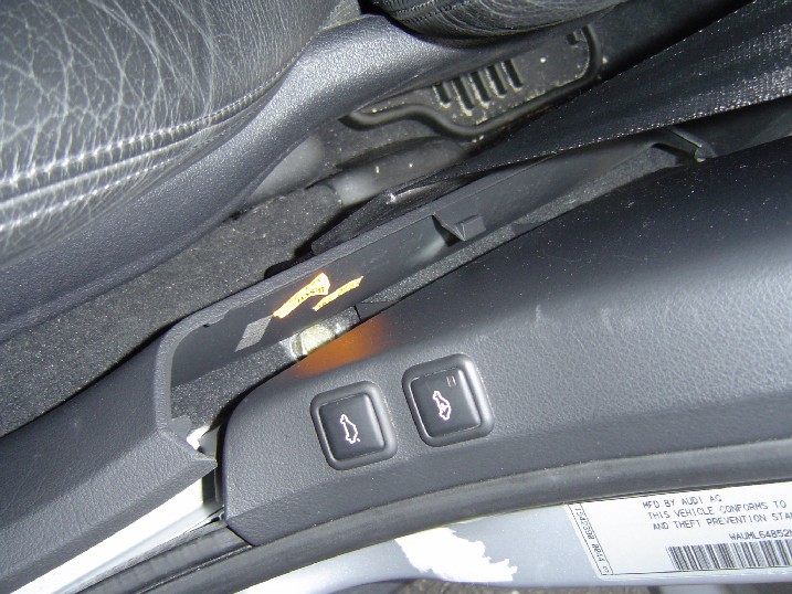
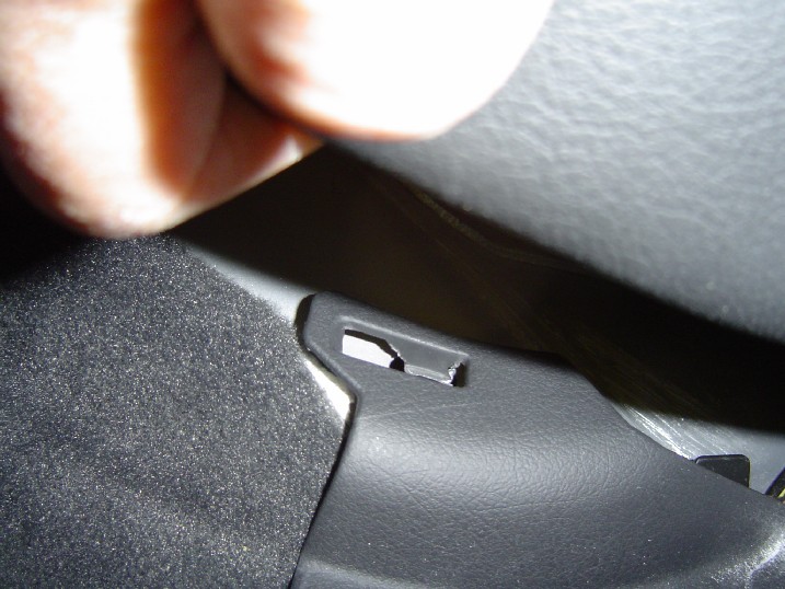
This trim piece is the triangle trim around the triangle window, and is what actually retains those BIG curved tabs of the rear deck. Along rearward edge of the C/D-pillar trim, you should see a few T-25 torx bolts tucked up there, maybe hidden by the side curtain airbag. You can see them in the pic below, just below the airbag. Remove those bolts, and then pull toward the center of the car to release the metal clips.
Rear seat removal
The rear seat has to be removed because the outboard shoulder belts go through the rear shelf. Poor design IMHO. Here is a post I did about the rear seat removal.
With the rear seatback removed, also release the lower anchor points of the outboard seatbelts. With the side bolsters (the side cushions closest to the rear doors), use a 17mm socket to remove the lower anchor bolt for each outboard seatbelt.

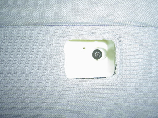
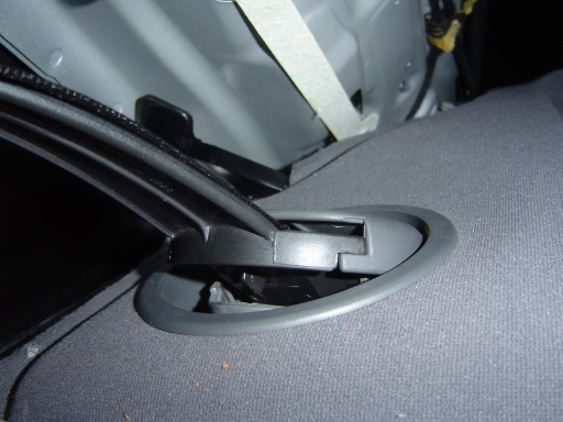
The seatbelts then can be fed down through the holes in the rear shelf. Remove the plastic caps that cover the holes, pictured below. Careful with those plastic caps that cover the hole in the rear shelf...they break easily. However, if you break them, they are cheap to replace (about $2 each...I broke one oops!). Just use a small screwdriver and gently pry the tabs just below the slot where the seatbelt passes through, and under the seatbelt guide show in this pic.
2) Removing the rear shelf
Rear shelf removal
There are three metal clips along the forward edge of the shelf that are released by pulling toward the front of the car, and another three metal clips underneath, approximately midway between the front and rear edge of the rear shelf. Very easy to remove, just pull the shelf to the front of the car, and the metal clips should release.
Sorry, no pic of those clips or the rear shelf removed, but here is the under-frame of the shelf, and you can see one of the slots where the metal clip was located on the forward edge of the rear shelf.

3) Pre-wiring for sunshade power and control
Okay, now that we are done removing stuff, time to begin installing stuff. With the rear shelf and rear seat side bolsters off, this is a good time to run the wire for the rear shade. Three wires are needed here with the connector to the rear shade control unit, including: 1) power, 2) ground, and 3) control. You need enough wire to run from the 3rd brake light to the lower A-pillar, probably 20 feet to be safe...easier to cut extra off than to add.
I will qualify my install with the following disclaimer: I got all the connectors from my previous car along with as much wire as I could fish out, so my wires are tapped into the existing OEM wires with in-line fuse taps.
Starting with the connector in back that goes into the control unit under the rear shelf, leave the connector hanging by the 3rd brake light, and run the three wires (red/blue=power, brown=ground, black/brown=control) along the rear deck...

Then run the wires along the driver's side C/D pillar area. I use a long zip-tie to fish the wires through the existing wire ties so the new wires are secure.


Then run the wires down behind the rear seat side bolster...

Loop up the excess wire, and leave in the rear foot-well area for later. We'll run the wires under the door sills and lower B-pillar later.
4) Installing the new shelf with power sunshade
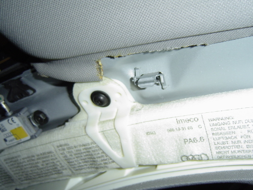
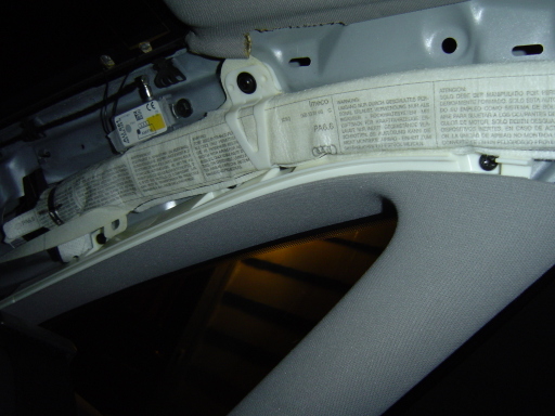
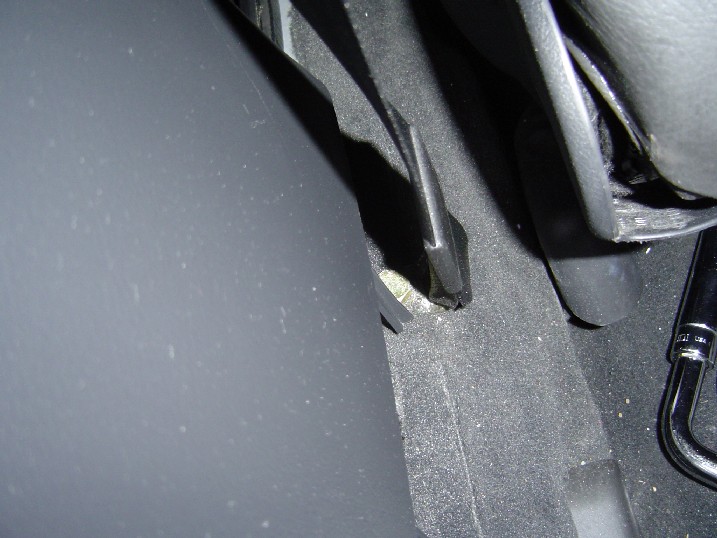
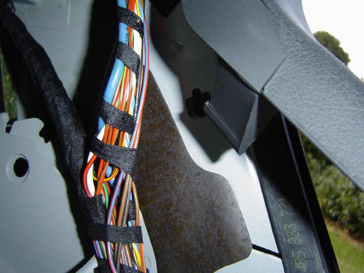
First, inspect the inside edge of the front of the shelf to make sure the clips that fasten into the slots along the front edge of the metal rear shelf are in place. Using extreme care (this thing is heavy) slide the shelf into position. Make sure that the 4 tabs on the rearward edge slide into the slots along the bottom of the window (see the picture below), and make sure you do not pinch the wire for the park-assist speaker (like I did...I had to remove the shelf and repair the wire...see it sticking up in the picture?)...
Once the shelf is snapped into place, there are three torx bolts that need to be fastened under the shelf...

Reinstall the rear seat and the C/D-pillar trim. I would suggest that you install the seat and side bolsters first so you have a nice surface to sit on when you install the pillar trim. One tip: make sure you seat the two tabs on the bottom of the C-pillar (the long piece) into the slots on the outer sides of the rear shelf. I found that at night, with lights on the interior of the car, you are able to see the reflection of the slots in the rear window.
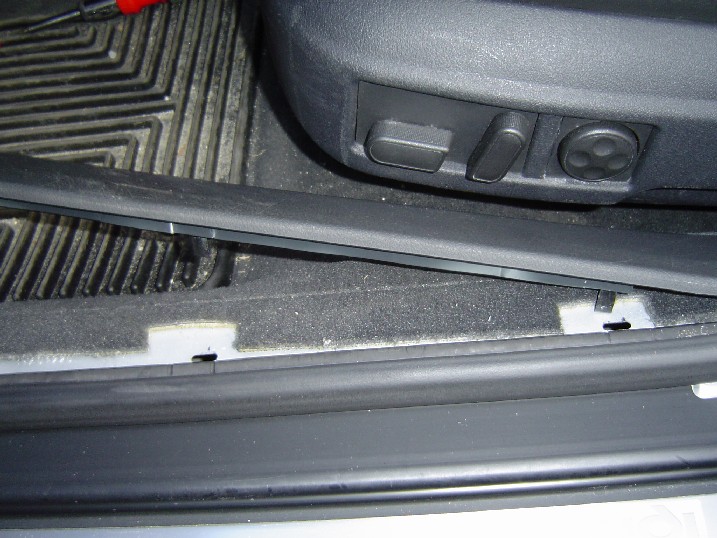
5) Running to wires to the lower A-pillar
I ran the wires along the floor under the carpet along the lower edge of the door openings. All this requires is to remove the plastic trim for the lower A-pillar, the long flat trim that runs along the lower edge of the door front/rear doors and under the lower B-pillar, and loosening the plastic trim that is next to the seat bottom.
Lower A-pillar removal:
Remove the little plastic cap on the lower A-pillar trim to expose one of the screws that has to be removed.

Remove the two Philips-head screws.
Remove the trim by pulling out towards the rear of the car first, then remove the top part of the trim from the rubber door gasket. There are two metal clips that fasten the trim to the door gasket (sorry for the blurry pic).

Lower B-pillar trim removal
Open both doors on the driver side of the car, and just grab the inner part of the trim with your fingers and lift up. Simple metal clips are used to fasten the front portion and rear portion.

Once the flat portions are free, then pull the center portion towards the inside of the car to release the tab that is hooked under the plastic center trim.
Remove the seatbelt bolt
The lower B-pillar trim hides a 17mm bolt that secures the front seat belt. I decided to run the wires along the rail but just under the carpet, which requires that this bolt be removed. There is not a lot of room to work with, and this bolt is tight, so I used my Audi-brand 17MM lug bolt wrench to free the bolt, then a regular socket wrench to do the rest.
Removing the lower C-pillar trim
Similar to the other trim, this is held in with a few clips and tabs. Just pull the trim toward the front of the car. Once the upper part is free, lift up on the front corner of the rear seat bottom to release a tab that is hidden under the seat. Remove the trim.
Running the wires
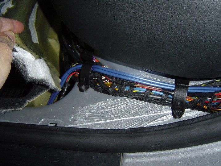
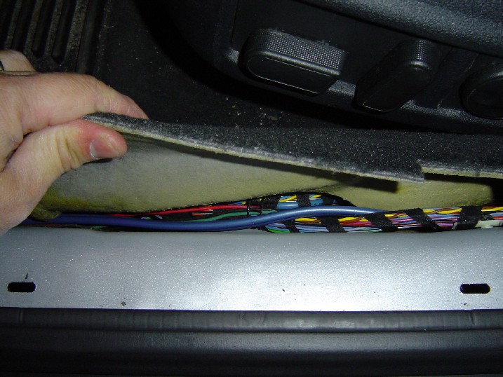
Now that the path is clear, time to run the wires! I ran the wires along the side rail, tucked under the carpet [Note: these pics taken from my DVD player install, but you get the idea].
I ran the wires to the front near the deal pedal, and coiled up the extra length and ticked everything under my floor mat until I was ready to finish the wiring. Reinstall the lower trim pieces in reverse order of removal, starting with the lower C-pillar, the lower B-pillar, but leave the lower A-pillar removed.
6) Switch installation and final wiring
Now that everything has been run to the front of the car, time to install the switch and make all the required connections. This will require removal of the lower dash panel, removal of the radio, removal of the switch bracket just above the radio, and removal of the cup-holder above the radio.
Lower dash panel removal
Remove the dash panel to expose the battery leads. There are 5 bolts that secure this panel. Two are hidden under the upside-down U-shape trim just above the steering column, one is in the fuse panel on the side, and two are located in the lower corners of the panel. To access the two upper bolts, pull the trim over the steering wheel straight back. Remember, you are removing the BOLTS, not the philips head screws (which are for the instrument cluster). Here is a pic of the panel removal (courtesy of TeddyBGame).

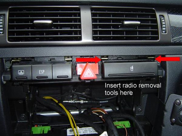
Radio Removal
Using the proper tools, remove the radio by inserting into the slots in your radio or Nav unit. [Note: This pic taken after I installed the switch, but you get the idea]

Removal of hazard trim, cupholder, and switch bracket
Now that the radio is out, you can more-easily remove the trim surrounding the hazard switch. Using a plastic putty knife, start at one of the lower corners and gently pry outward. There are 6 clips that hold that sucker in place, and chances are you will break at least two of them in this process [sorry no pic].
Once the trim is removed, you may now remove the cupholder. Using the radio keys or something else thin and flat, insert them into the slots in the upper corners as pictured here:
Then remove the wire that provides the icon light:

Remove the switch bracket in the same manner, but you might need to pop off one of the blank buttons and use a pair of needle nose pliers to pull the bracket assembly out. This is where you need an extra set of hands, to release the tabs in the upper corners that lock the bracket in place, and to pull the bracket out. Once the bracket is out, you are ready for the switch install and wiring.
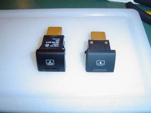
Here is a pic of the rear shade switch. The one on the left is for the 2001 and earlier (glossy plastic) and the one on the right is for the 2002 and later (rubbery plastic).
Here are the part numbers:
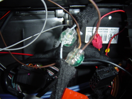
There is a wire connector for the sunshade switch that has 4 wires: one is for power, one for ground, one for the shade control unit, and one for accessory (which tells the switch to light up when the lights are on). Instead of trying to figure out where to tap the wires unde the dash, I took a bit of a shortcut for the ground and accessory. I used the wires from the cupholder, since it is close and serve the same purpose. Here I tap into the ground (brown) and the accessory (gray) wires. Phone wire taps rated for AWG22 wire work great!
Now I connect everything to the switch harness (note, I cut the harness out of my last car, so I am just using taps to add wire length as needed).

I ran the wires down through the tunnel where the switch bracket goes, then down the back of the radio cavity, and to the lower dash area. Then I was able to insert the switch into the bracket and connect the wire harness I just completed.

So, now you have two more wires to connect, power and control. The power wire can just run to one of the switched power leads under the dash. That will come later, but simply attach a ring connector to the end of the wire. The control wire must run to the wire connector shown below, which also handles the power wire for the shade motor itself (the wires I left in the end of step 5). I am going to call this Connector A, which has a male (left) and female (right) side.
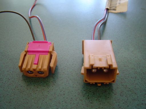
Here is where I needed to pay more attention to make sure I made the right connections.
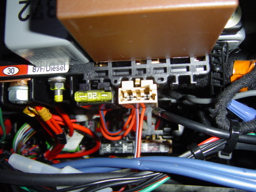
First, the wire for the control from the dash switch needs to run to the male end of Connector A (the black/brown wire). Then, a red wire for power must be run to a dedicated fuse holder shown below, which I will call Connector B.
Then another wire can run from Connector B to one of the power leads under the dash. Once the wires are connected, Connector B can be snapped into place as shown below.
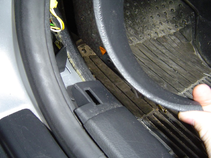
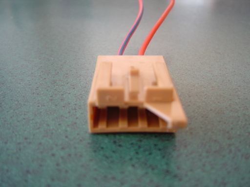
The power and control wire from the female end of Connector A can be connected to the wires left from the end of step 5. Once those connections are made, snap Connector A into the spot shown below, just above the yellow connector in the lower A-pillar area.

Lastly, take the ground wire that was run from the back of the car to a ground source under the dash, and connect the power wire from the shade switch to one of the battery leads. Insert a 10AMP fuse into Connector B, power the car on, turn on your parking lights and see if the switch lights up.

Click for a short movie of the sunshade in action
|