| Tech Article Title
|
Author
|
Date
|
| Integrating the Genie Intellicode Mini-Transmitter into the Audi A4
|
Edward Palisoc
|
1999
|
INTRODUCTION
Tearing into an expensive car (again), or even worse, never worked on a car at all, makes for an interesting experience. The following article outlines my journey. Several things to note concerning this article:
You assume all risk from using the information contained in this article
This article was based on an 1999.0 2.8 Audi A4 Quattro with the following options: Bose sound system with 6 disc changer, Tiptronic, All other options except sport seats and trip computer.
I am a neophyte when it comes to electronics and soldering
PLEASE verify parts numbers with your dealer or supplier before ordering! With that out of the way, here's what I did to make it all work.


THE GOAL
It's important to me that whatever modification I do to my car, there is no evidence of it being a modification. As with the Nokia phone install I wrote about before, I didn't want the integration of the garage door opener to be obvious or cheap in appearance. We all pay too much for this car to have things look out of place. If there was not a way to use the features or opportunities available, I was not going to attempt this project. That may make some folks out there breath easier come time to sell or return the leased car.
This article is composed of the following sections:
Parts Summary: outlines the overall components needed to complete the project.
FAQ Summary: outlines the list of FAQ's I referenced on the AudiWorld site to complete the project.
Tools Summary: outlines the tools I used for the project.
Details: description of each major component outlined in the Parts Summary, and explains the steps involved preparing each component.
PARTS SUMMARY


|
Mini Remote
(For Intellicode Products Only)
Description: 2-Function Mini Remote Control with Intellicode.
Manufacturer: Genie
Model: GMIC90-2BL
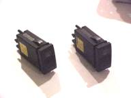
Defroster Switches
Description: Timed Operation Momentary Switch
Manufacturer: Audi
Part Number: 4D0 941 503 01C
Wire Connector Block
Description: Connector Block that Accepts and Plugs into Switch
Manufacturer: Audi
Part Number: 8L0 971 972
Wire Connectors
Description: Terminates 18 gauge wire and Plugs into Wire Connector Block
Manufacturer: Audi
Part Number: N 904 219 02
18-Gauge Wire
Description: 18 Gauge wire
Manufacturer: Belden (doesn't really matter)
Part Number: Like I said....
|
FAQ SUMMARY
Instructions for removing the radio can be found here:
http://www.audiworld.com/faq/faq_elec/faq8.shtml
TOOLS SUMMARY

|
Multimeter
Crimpers / wire stripper
Soldering iron
Flux (non-acid)
Radio pullers (mine came courtesy of my dealer (Jim Ellis, Atlanta)
Mini screwdrivers
Optional, but came in handy - batterypowered dremel tool with cutting disk
|
DETAILS

|
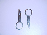
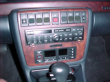
The first task is to remove the radio. Audi makes stamped metal tab tools, and make removing the radio a breeze. Convince your dealer to cough one or two up, since they tend to have a bunch
lying around. If not, there is a FAQ listed above that describes the procedure for removing it
without the tools pictured. I did not have any luck though, but perhaps you may fare better than I
did.
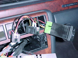
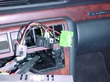
Once you have the radio out, you can better access the switches on the right side. The three just to the right of the hazards are dummies, and can be easily removes with a flat screwdriver before removing the radio, or pushed out from behind once the radio is out of the way.
Now remove the passenger side seat warmer switch by first pushing up on the back of the switch
housing, then pulling it out from behind with your fingers in the radio slot. The switches are held in place with spring clips (you'll see what I mean if you bought the switches, or looked closely in the following photos), and may require some force.
With the switch pushed out, pull the switch out of the connector block, and set it aside for later when you reassemble everything.
The genie garage door opener runs on 12 volts; therefore, is perfect for being tied into the car's system for permanent power. The intent is to tap into the seat warmer switch for two power
sources:
1. switched power to run the garage door opener
2. power to the lights in the switch, so the switches light up with the headlights are turned on.
I decided to tie the door opener to switched power instead of direct unswitched power for two
reasons; crude security (keys are required to operate), and I didn't want to wire into the hazards
(the only immediate source of unswitched power).
This arrangement means that only three taps are required into the seat warmer switch - ground,
switched power, and power for the lights. The seat warmer switch has six (6) contacts - the ones that I tapped into are as follows:
contact no. 1: 12+ volts for lighted switch LED
contact no. 2: ground
contact no. 5: switched 12+ volt power
The contacts are numbered on the back of the connector block in VERY small numbers - look on
the back of one of your connectors you purchased. PLEASE VERIFY THIS INFORMATION WITH A MULTIMETER! It is possible that wiring changes may occur during the production line, and between model years. With the ignition alternating between on and off, contact no. 5 should show 12 volts when the key is turned, and contact no. 1 should show 12 volts with the headlights turned on.
|

|
Next, open one of the switches - it's easier if you use a small eyeglass screwdriver to lift under the snap tab at the back of the housing. The housing is not glued together, and should open easily. The picture to the left has the case partially open. Note the spring clip that holds the switch in place in the console.
|


|
The best thing is to gut the switch PCB; that is, desolder all of the components not necessary
from the circuit board - but NOT the LED's and the contact switch! The picture on the left is of the gutted board with some of the rerouted wiring in place. This is where the Dremel tool came in
handy. The board has two relays, one large - it can be difficult to desolder - I ended cutting most
of it away before desoldering the remains.
Before anything else, program your garage door opener to recognize your transmitter BEFORE
CONTINUING. If something goes wrong, you may not know if it is the transmitter, the project
wiring, of what. Verify that the transmitter is in working order before you start modifying it.
Now if you open up the mini transmitter, you'll notice that the circuit board is almost the same
size as the switch ciruit board. in fact, it'll fit in the housing! The images on the left shows the sandwiched boards. You'll need to notch the transmitter circuit board so it won't block the travel of the push button action. Just line up the notches with the cutouts on the switch circuitboard. It is important to note that notching the board cuts two circuit tracings - these go to the LED for the mini transmitter. IT IS IMPORTANT that you properly reroute these tracings to the LED's on the switch circuit board (the clear LED's - the red one is for the night lighting), or the transmitter WILL NOT WORK. The circuit that drives the LED must be complete. I wired the LED's on the second switch inseries to the ones in the first switch using contact no 6. Ground is already passed on thru contact no.2, so you do not need two contacts.
Now, you have to desolder several parts from the transmitter, namely the battery contacts, and
the switches. you will be rerouting the switch contacts to the one on the switch circuit board.
Here is the second caveat - they also may change circuit board layouts, so it is important that
you check for yourself the electrical paths to accomplish what the goal is. You want the contacts
on the switch circuit board to close the connection on the transmitter board.
Now reroute the negative and positive power requirements for the transmitter to points on the
switch circuit board so that they connect to the proper contacts, ie. ground from the transmitter
board to contact no. 2. Test everything with the multimeter, using the continuity setting.
At this point, one of two things happen. I have two garage doors, so the transmitter can operate
both. This means I need to wire up another switch to pass the contact switch from another switch
to the one I just rewired. To do this, I used the other contacts on the rewired defogger switch to
pass along the electrical connections. If you only have one garage door opener, you're in luck,
you don't need to wire up another switch.
For those that do have to wire up another switch, this one only needs to pass along the closed
contact connection to the other (master) switch/opener. I used contacts 3 and 4 to do it. In the
main rewired switch, I simply connected contacts 3 and 4 to the other switch on the transmitter
board.
|


|
You must now make the wiring for the connector blocks. Here, a picture is worth a thousand
words. If you have two switches, just connect contacts 1 and 2 in serial so that the light will work with the headlights. the "secondary" switch does not need the switched power since that only is used to power the transmitter in the first switch housing.
Close up the housings for the switch and test to make sure the pushbutton action is not
catching.
You MUST use the special Audi wire terminators - they are the only things that will fit in the
switch connector. The ones in the seat warmer connector are easily removed by jamming a
VERY small eyeglasse screwdriver between the connector housing and the wire terminator - it
too uses a spring clip to hold it in place. jamming it in folds down the tab, so do it top and
bottom. once the termitator is out, cut off the old one, join your splice and audi wire with a new
one using the crimper, and reinsert int the housing. CAREFUL - there is not alot of wire to make
mistakes with. Cut off too much or screw up, and you could be stuck with not enough wire to get
it all back in place. Again, I had two openers to operate, so you'll notice wires in series to power the night lights in the switches, and signal connections for the second opener.
At this point IT IS IMPORTANT TO TEST THAT YOU ARE NOT SHORT CIRCUITING ACROSS
CONTACTS! Use your multimeter often to verify that your rerouting and connections are accurate.
Before snapping the switches into place, plug the switches into the connectors and do a trial run. Then close it all up and enjoy.
I know it seems complicated, and it is to some extent. Many of you nay not think the project is
worth the trouble. Be it as it may. The concept is relatively simple, but it takes time and patience. I found the trouble satisfying and worth the effort. I hope you do too.
Happy driving!
|
|