|
|
N122 To my knowledge, this part is found exclusively on 97-99.5 A4 1.8T models. However, older 12V V6 engines use a similar part. Email me for specifics. Disclaimer Usual disclaimer applies here, I am not responsible for any of your work. This procedure is done at your own risk, and my write-up is merely a guide to help you do it (as model years and options vary). That said, this isn't rocket science, so there's very little risk of anything going wrong. Background A few months ago, my N122 module failed. Problem came on suddenly and was characterized by horrible idle and a blinking check engine light (CEL) / Malfunction Indicator Lamp (MIL). In researching the Audiworld archives for possible sources to my problem, my attention immediately turned to my coil packs. My VAG-COM told me that I was misfiring on cylinder 2. I immediately tried the typical swaps (plugs, ignition coil) between cylinders to no avail. Cylinder 2 still dead. At that point, my search took me to the Power Output Stage module N122 (p/n 8D0 905 351 or 4D0 905 351). I've seen at least four different terms used to describe this part (see heading above). This part is located on top of the factory air cleaner box as indicated here:  Geeky stuff The wiring diagram for the ignition system is here:  Those with experience reading electronic schematics will see that the term "ignition amplifier" is a bit of a misnomer because this N122 module doesn't amplify anything. It's a simple switch. It takes impulses from the ECU (b1, c1, d1, e1) and, in turn, connects the primary coil of each ignition coil (e.g., terminal 1 of coils N, N128) to ground via terminal 3 on the 5-pin connector on the module. When current can flow through the primary coil (from terminal 15 to 1 to ground at ground connector 83), this will excite the secondary coil (from spark plugs P to terminal 4a to ground at ground connector 18). Then end result is BANG, spark plug firing. The N122 operates just like a FET (field effect transistor). When an impulse is detected at the "gate" input (at the 5-pin connector) to the N122, a conductive path is created between the corresponding "source" terminal (at the 4-pin connector) and "drain" terminal 3 on the 5-pin connector. This procedure simply statically verifies this functionality. Just a note, my pseudo-educated guess for the reason why Audi and VW have been seeing coil pack problems pertains to this functionality, which was relocated from this N122 module into the individual coil packs in 2000. Thus, while newer A4 owners have to deal with coil pack problems, us older A4 1.8T owners deal with N122 output stage problems. But I digress. On to troubleshooting. Once you've swapped spark plugs and ignition coils between misfiring and known-good cylinders and verified that the misfire stays on the same cylinder, this procedure will then verify for you whether the problem is indeed a faulty N122 module. For this procedure you'll need: Things Needed 1.5 Volt battery (any size, but larger will be easier to physically handle) 1/4" female speaker crimp terminal (optional if you don't have a spare set of hands) Multimeter Foot long piece of speaker wire Tape Procedure First thing you do is strip the ends of the speaker wire and tape one end of the wire to the battery. Tape one wire to the + end of the battery and the other wire to the - end of the battery as shown (obligatory watch for scale). At the opposite end of the + battery wire, crimp on the 1/4" speaker terminal. The opposite end of the - battery wire is simply stripped.  The next step is to wrap the - battery wire around the common/ground DMM probe. At this point, battery voltage can be measured simply by touching the + DMM probe to the speaker terminal. Cheap radio shack battery doesn't even put out a full 1.5 volts. No matter. Now set the DMM to measure resistance on a KOhm scale. 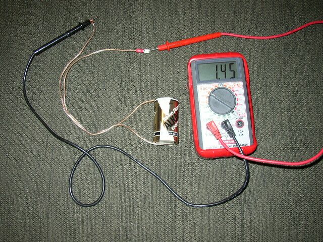 Next, we hook up the speaker terminal to one of the input "gate" terminals on the 5-pin connector. At the same time, touch the common/ground DMM probe to terminal 3 on this same side. This common/ground DMM probe stays on terminal 3 throughout this procedure. Only the speaker terminal and + DMM probe change positions to measure continuity for all 4 cylinders.  On the 4-pin connector side, touch the + DMM probe to the output terminal directly opposite the terminal to which the speaker terminal is attached. In this image, the opposite side connections are omitted for ease of picture taking. Just bear in mind, the right-most terminal on the 5-pin side corresponds to the left-most terminal on the 4-pin side. In this image and the image above, we are checking resistance (continuity) for cylinder 4. The whole setup is shown below. 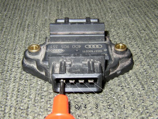 Here, I'm getting a reading of about 270 ohms. When the car is running, the ECU probably outputs something like 3.3 or 5 volts. My guess is that if we applied this much voltage in this test, the resistance would drop closer to zero ohms. But for purposes of checking proper operation, our 1.5 volts does the job. On my N122, I got somewhere close to 300 ohms for cylinders 1, 3 and 4...  But for cylinder 2, my DMM shows a 1, indicating open loop, no continuity, no ground connection, and hence, no spark. Bottom line, dead N122. 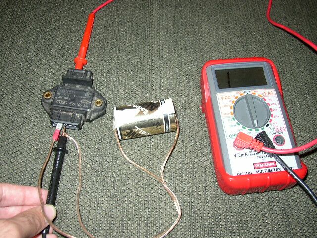 In performing this test, you should see similar resistance numbers for all four cylinders. If you find that resistance for any cylinder is abnormally high or completely open, then the N122 is dead. Call the dealer, visit your favorite auto parts website, or find a friend with a spare (Thanks Steve!) and swap out the part for a new one. |
|
Advertising |
Contact Us |
Cookie Policy |
Privacy Statement |
Terms of Service |
Do Not Sell My Personal Information
© 2020 MH Sub I, LLC dba Internet Brands |