Disclaimers
- You are performing this modification at your risk. This particular
modification is categorized as super easy.
- The description as shown here is for a US-version, 98.5 A4 2.8 quattro
with manual transmission and all features. Your car may be differently wired
if it is not of the same category. All A4s from the 99.5 model year on have
this feature standard, you don't need to do this!
- You may not really want to do this. Some people may be disturbed by the
idea of having a red light on at all times. Since the light is very gentle,
I already got used to it.
Purpose
Ever since driving my dad's new A6, I wanted it. I wanted to see my hand when
touching the radio when driving at night. Wanted to just barely see things
around me. To be able to find the sunroof switch or the map lights in darkness.
This LED based light will illuminate the area directly below the dome light. No
visible changes on the interior lighting will be performed. All work can be done
in the comfort of your home, short of removing and re-installing the lamp unit
of course.
This description includes some bug fixes. On some cars, in the original
version, the sunroof stopped functioning properly. Thanks to Rich Quinlan for
coming up with the bug fix!
Requirements
- For this to work, you must have a sunroof.
- A pre-99.5 A4. If you have a 99.5 or newer, you already have this
feature.
- About 1 hour, depending on skill
- Soldering iron and accessories
- One super-bright 5mm red LED (such as Radio Shack part #276-087A). Not
thicker than 5mm, please.
- One resistor in the 80 - 560 ohm range, based on preference and LED used, see
calculation below.
- One small diode (such as Radio Shack #276-1101A micromini silicon diode)
- Some thin wire
- Philips screwdriver
What LED should I choose?
First of all, the LED must be red as otherwise your night vision will be
impaired. Second, the LED should be 5mm in diameter because otherwise it will
not be a perfect fit for the dome light. The most important part is the light
output of the LED: anything above 1000mcd will work (2000mcd or more is better,
leaves you more space to play). All packages specify the light output. The
proper value is about 1000-2000, but feel free to get a 3000 or even 5000mcd LED
because you can always reduce its light output by increasing the resistor value
above the minimum (see formula below). I have one 2000mcd LED running at about
80% output.
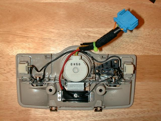
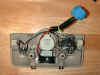
Take out the dome light. To do this, first pull off the Plexiglas, which just
snaps out. Loosen two screws which attach the unit to the ceiling. Pop out unit
by pressing the two metal springs and pulling down. Disconnect the black power
cord at the base of the light, and the sunroof wires (blue connector) between
roof and ceiling cloth (this part takes some tweaking, watch your fingers).
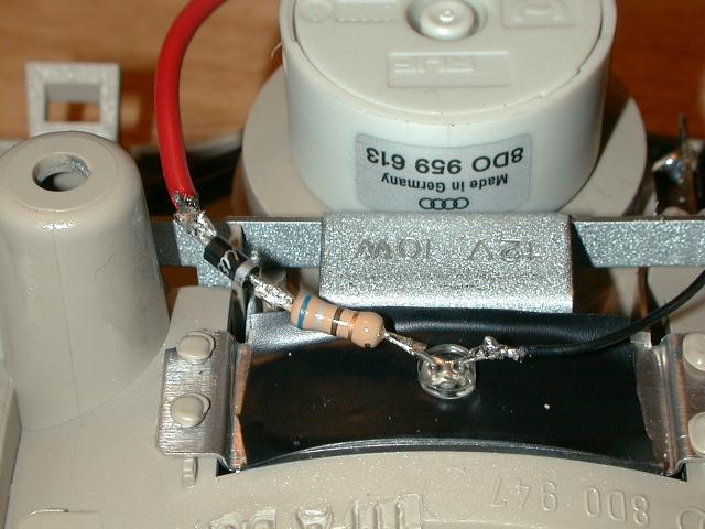
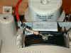 Place
unit on desk. We need to stick the LED through the center hole above the center
light bulb. The LED diameter is 5mm and actually just perfectly fits. I suggest
you put some isolator tape under the LED as to make sure the wires don't touch
the metal. Make a tiny hole through the tape and then push the LED through this
hole. This will nicely hold the LED in place. Mark the Anode (+), longer leg,
and then cut both legs to be really short. Attach the resistor of your choice to
the Anode. Put the diode in series with the setup (doesn't really matter which
order) - the stripe at one end of the diode should be facing toward the LED, see
picture.
Place
unit on desk. We need to stick the LED through the center hole above the center
light bulb. The LED diameter is 5mm and actually just perfectly fits. I suggest
you put some isolator tape under the LED as to make sure the wires don't touch
the metal. Make a tiny hole through the tape and then push the LED through this
hole. This will nicely hold the LED in place. Mark the Anode (+), longer leg,
and then cut both legs to be really short. Attach the resistor of your choice to
the Anode. Put the diode in series with the setup (doesn't really matter which
order) - the stripe at one end of the diode should be facing toward the LED, see
picture.
What is the diode doing there?
The diode was put into the circuit after the first implementors had problems with the sunroof switch not functioning after the modification. When you do your math, you will realize that even though the LED is a diode, it's reverse current is too small. The volatge used for our circuit is taken from a control circuit and it is possible that it would cause a direct flow of current thru the diode in the undesired direction - thus the added diode. I didn't realize it at first either, and it worked for me, but some folks had problems. Lacking a proper documentation of the sunroof circuit, this diode ensures that the LED circuit is fully isolated from what the Audi engineers had in mind.
How do I pick the right resistor?
Good question. First of all, a resistor is specified for a given wattage (W),
current (A), and / or voltage (V). And of course the resistance. The reason why
I don't specify W, A, and V is that pretty much any resistor will do. We will be
drawing so little current at such a small voltage, that the tiniest resistor
will absolutely do (we will be dealing with less than 200mW, less than 1/4W).
The tolerance is also negligible for our purposes.
The only thing that matters is the resistance. This value of the resistor
depends on two things. First, the resistor must have a minimal value because
otherwise you will fry your LED. This value can be computed from the voltage
which we are supplying, the voltage the LED can handle, and the current the LED
takes. We will be tapping into the sunroof power wire, which leads around 4V
(3.8 - 4.2) as strange as it sounds. The general formula is:
R = (U - UL) / IL
where R is the minimum resistor value, U is the voltage we are supplying, UL
is the maximum voltage of the LED (marked on the box), and IL is the current of
the LED (also on the box). For instance, my Radio Shack super bright LED lives
at 2.4V at 20mA. If we are feeding it 4V, the minimum resistor value is (4 -
2.4) / 0.02 = 80 ohm. If you go below this resistance, bad things will happen.
Now this is the minimum resistor. Thing is that the super bright LED's are
really bright, and we probably don't want that much light. So by increasing the
resistance we decrease the current through the LED and it gets dimmer. My LED
wanted a minimum of 56 Ohm, and I ended up with 270 after finding 560 too dim.
You should experiment.
What if I want more than one LED?
Ok, here is where the fun begins. First, ask yourself why
you would want to do this. One option is to have tiny LED's through drilled
holes at the map light switches (I thought about that one), or two more LED's in
the map lights. I think this is overkill but some people apparently wanted to
know.
I would use identical LED's. Then we have the same voltage for all of them,
that's a start. In computing the resistance, we just add their max. current
together and stick it into the IL value above. Thus, three identical LED's on
one resistor, IL = 3*LED current as written on the pack. Attach all the anodes
to one end of the resistor.
If you want different LED's, you need to compute each resistor individually.
Do all math independently and attach all resistors to the sunroof power source,
feeding each LED from its own resistor.
Procedure
Why do we tap the sunroof?
The sunroof wire has many good habits. If we used the "constant
+12V" wire that we have in the light, we would have the LED run all day,
all night, even if parked. At 2.4V and 20mA, we would drain the car battery
already after six months (so even if you don't have a sunroof, you really can do
this if you don't mind having a dim red light on all the time, just compute the
proper resistance for +12V). The sunroof is on whenever the ignition is on, plus
10 minutes or until the door is opened, whichever comes first. So this is pretty
much our perfect power source.
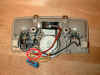
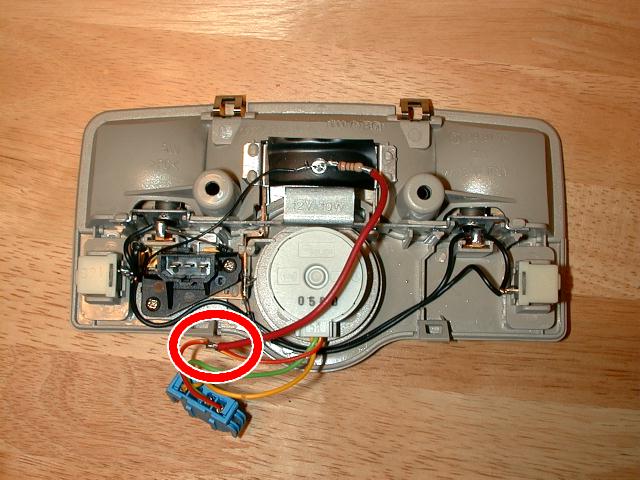
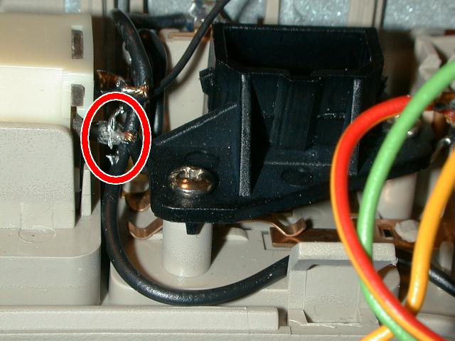
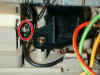 The
wire we are looking for is the red one (red with thin yellow stripe on some
models - it's the wire that goes to the right hand pin of the sunroof connector,
the closest to the passenger side). Splice into it and attach a piece of wire,
leading to the diode, and from there to the resistor. (Only the first
image in this description shows the diode included in the setup). Then tap
the ground wire and with a second wire attach it to the Cathode of the LED. The
ground can be found at the bottom (when inverted on the table) of each of the
map light switches, see circle.
The
wire we are looking for is the red one (red with thin yellow stripe on some
models - it's the wire that goes to the right hand pin of the sunroof connector,
the closest to the passenger side). Splice into it and attach a piece of wire,
leading to the diode, and from there to the resistor. (Only the first
image in this description shows the diode included in the setup). Then tap
the ground wire and with a second wire attach it to the Cathode of the LED. The
ground can be found at the bottom (when inverted on the table) of each of the
map light switches, see circle.
 Now
install the good thing. Make sure you attach the Plexiglas diffuser. Best is to
park inside absolutely dark garage and see whether the light level is good
(ignition on). During experimentation phase it is a good idea not to press the
sunroof plug firmly into place, as removing it is a bitch as I am sure you
noticed. If there is no light, you may have tapped the wrong wire or confused
cathode for anode. If not happy, increase or decrease the resistor value until
happy. Once satisfied, make sure you put the original wire loom around the
sunroof wire as it is prone to chafing at the cutting edge. Secure the light
with both screws.
Now
install the good thing. Make sure you attach the Plexiglas diffuser. Best is to
park inside absolutely dark garage and see whether the light level is good
(ignition on). During experimentation phase it is a good idea not to press the
sunroof plug firmly into place, as removing it is a bitch as I am sure you
noticed. If there is no light, you may have tapped the wrong wire or confused
cathode for anode. If not happy, increase or decrease the resistor value until
happy. Once satisfied, make sure you put the original wire loom around the
sunroof wire as it is prone to chafing at the cutting edge. Secure the light
with both screws.
Beware, people can now see where your hands go at night :-)