| The Design |
|
|

The two circuit boards (the "brain"
and the remote display board). The sensor has been already soldered in
place.
|
The documents for the design started with
the application circular from Motorola. The document outlines the ease
of taking the output of the pressure sensor and outputting it to an LED
display driver. The problem is that the MPX5100 that the circular
uses, is only good for 15 psi. Most chipped turbos can surpass that by
quite a bit. Turns out that the MPX 4250AP
is rated for 36 psi, and made to monitor manifold pressures in turbos;
it's an MAP (manifold absolute pressure) sensor. Keep in mind that this
sensor differs from other types; it measures pressure against an near
vacuum, so at sealevel, it's generating an output equivalent to 14.7 psi.
There are others that are non absolute, but this sensor can potentially
be made to read vacuum as well, or a psi less than normal atmosphere.
That project is for a later date.
Taking this schematic outlined in the circular, I used a PCB-CAD design
program called Eagle Editor to
make files that I could output to a company that could fab the boards.
The software is freeware if the files made are not used for profit, and
there are size limitations. Needless to say it fit the bill. There are
two files that get generated, a schematic design
file, and a board layout file. These
are then used to make output (plot) files that are used to actually make
the boards. The board layout is actually two boards. To save costs, I
made both onto one piece of fiberglass, and then cut it myself along the
heavy horzontal line.
The design also offers the ability to change the visual display. There
are two modes, selectable by a jumper. You can set it to either have a
single moving dot, or a bar graph. When jumpered, it will show a bar graph.
To minimize the number of wires needed to go to the display, I used a
common anode approach to reduce the wires to 11 (one neg per LED, and
one common source). The closest was a 14 pin ribbon cable.
|
|

The pressure sensor. Very small package.
|
The parts required for the project are mostly
available, but the pressure sensor was a bit hard to source. I got them
from www.newark.com. Here is the entire parts
list, with where I got them from, the quantity, the parts numbers, and cost.
It does not reflect the cost of the PCB boards (35.00 each), nor shipping
and taxes. |
|
Code
AP1
C1
C2
C3
R1
R2
R3
R4
R5
R6
U1
U3
|
Item
MPX4250AP
0.1uf Capacitor
1uf Capacitor
1uf polarized Capacitor
Red LED's
Yellow LED's
Testpost- red
Testpost- blue
Testpost- green
Testpost- white
100 ohm resistor
1.2k ohm resistor
2.7k ohm resistor
215 ohm resistor
1k ohm trimpot - multiturn
100 ohm trimpot - multiturn
Connector - DIP14L
Connector - 2x7 PCB
LM3914N
MC78L05ACP
Cable 14 wire
Jumper Header 2 wire
Jumper Shunt 2 pin
Shielded 20ga wire Belden type 8762
6-32"x1/2" stainless steel machine bolt
6-32 hex nut - stainless steel
4x2x1 Project box
4mm Vac hose - silicone
Crimp Clamps
Zip ties
|
Quantity
1
1
1
1
8
2
1
1
1
1
1
1
1
1
1
1
1
1
1
1
4 ft
1
1
4 ft
2
2
1
10 ft
6
1 bag
|
Supplier
www.newark.com
www.mouser.com
www.mouser.com
www.mouser.com
www.mouser.com
www.mouser.com
www.mouser.com
www.mouser.com
www.mouser.com
www.mouser.com
www.mouser.com
www.mouser.com
www.mouser.com
www.mouser.com
www.mouser.com
www.mouser.com
www.mouser.com
www.mouser.com
www.mouser.com
www.mouser.com
www.mouser.com
www.mouser.com
www.mouser.com
local
Home Depot
Home Depot
Radio Shack
Local - NOPI
Local - Grainger
Local
|
Part No.
07F9899
80-T350A104K050
80-T350B105K050
140-XRL50V1.0
351-3232
351-3252
151-207
151-205
151-208
151-201
271-100
271-1.2k
271-2.7k
271-215
72-T63YB-1K
72-T63YB-100
151-2P14
517-3914T
526-NTE1508
513-NJM78L05A
517-3365/14FT
538-22-03-2021
571-3828115
local
30699-9648
30699-1991
270-1802
Local
Local
Local
|
Cost/unit
$ 25.00
$ 0.30
$ 0.32
$ 0.05
$ 0.30
$ 0.30
$ 0.28
$ 0.28
$ 0.28
$ 0.28
$ 0.09
$ 0.09
$ 0.09
$ 0.09
$ 2.82
$ 2.82
$ 0.77
$ 2.00
$ 8.18
$ 0.22
$ 0.28
$ 0.30
$ 0.09
$ 0.39
Same
Same
$ 2.96
$ 1.00
$ 0.39
$ 3.99
|
|

The pressure sensor with the leads bent.
Notice the flat top is "up". The pins have been prepped for
insertion onto the PC board.
|
I started by preparing the sensor. The leads
must be bent down so that they fit into the holes on the board. |
|

The board partially populated. The
ribbon cable connector is on the extreme right edge.
|
Locate the sensor on the board.
Place and solder the other components one by one, double checking that
they are going in the right place. The board layout file can be used to
locate the position of each component, and it's value are easily determined
by clicking on it.
I also then locate the ribbon cable connector. Be careful, as it is easy
to snap shut. IF this happens, it's tough to unlatch it. You will need
pliers to clamp it onto the ribbon cable.
|
|

The ribbon cable is attached. Note
the pin one indicator on the ribbon cable. This will orient towards D!
(first led) on the remote display board.
|
Next slide the ribbon cable into the connector. Make sure
it seats properly, so that when you squeeze the connector closed with the
pliers, it will clamp onto the correct wire. It's easy, just take your time.
Be careful not to squeeze too hard, as you are clamping onto the pins on
the solder side, and you don't want to create a short or damage the tracings. |
|

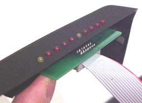
The ribbon connector on the remote
display board.
|
Next solder on the connector onto the display board. DO NOT
attach the ribbon cable yet! you need to prep the project box and slide
the cable thru the cable slot you will cut into it BEFORE you attach the
display board. Make the mistake, and you'll ruin the connector, and possible
the display board. The connector is one use only, and I have never successfully
reused one. Set it aside for now. Don't solder the LED's yet. |
|
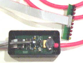
The "brain" with the vac
hose and display board.
|
An almost completed gauge. The project box needs to be prepped
to recieve the board. You will need to cut a slice in the bottom edge to
have the ribbon cable slide thru, a hole above it for the power cable, preferably
with a strain relief conector, and a hole for the vac hose to go into the
box. A side note. The nuts on the bottom of the board that holds the sensor
frimly to the board will conflict with two plastic standoffs. Simply cut
these away. |
|

Notice the blank boards in the background.
|
This is the main (only) tool I need. Note the cutting wheel.
It's a cordless Dremel. |
|
|
| |
|
| The Remote Display |
|
| |
|
|

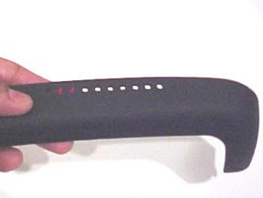
The column cover housing before the
display is inserted.
|
The display was made for the flexiblilty to locate it wherever
you'd like, within reason. In general, this portion of the document illustrates
how to place it into the plastic housing of column cover. |
|
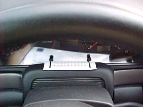
Align the template. Notice that the
heavy lines align with the adjustment sticks.
|
Take the template and center the heavy
lines with the adjustment stick coming out of the instrument cluster.
Also align the back edge of the paper template with the back edge of the
plastic cover. It is important that you not "eyeball it" after
taking the cover off. The sticks are NOT centered on the palstic cover,
so if you center the display holes with the cover, it won't look right.
Spray the back of the template with an adhesice, like Sprayment, or Photomount,
found at any art supply store. You can also use rubber cement, but the
idea is to provide complete adhesion of the template, because once you
start drilling, the paper template will shift if not held down well around
the holes.
|
|
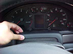
Template removed for clarity.
|
Now remove the plastic cover. It simply pulls towards you
with little force. |
|

The cover simply pulls forward.
|
Then lift up. |
|

The column with the cover removed.
|
Notice the opening and gap in the center where the ribbon
cable will emerge. |
|

The LED alignment as they will be located for the two
display options.
|
This photo shows the placement of the LED display. This particular
one is a variation that does NOT require drilling. It will simply stick
up more, and sit closer to the instrument cluster lense. |
|
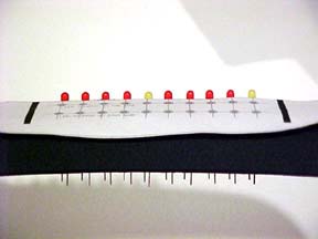
Notice the LED leads. They have not been trimmed yet.
|
A closer shot. Notice the two rows of holes for drilling.
The row closest to you should not be used, as there is not enough room to
get the board in there, unless you cut a hidden flange. This version of
the display will require some cutting of the flange to make room for the
ribbon cable that will need to wrap under the board to get back to the column
area. |
|

Notice the bottom plastic flange. You'll need to notch
it the width of the ribbon cable to give it room to pass. The leads on
the LED's have not been trimmed yet.
|
This is how the non-drilling method is located. There is enough
room between the clear plastic and the cover to do this. It will look up
over the cover as shown in the previous photo. |
|

Another shot showing the bottom flange.
|
Here it is again. Notice too, that the LED's mount on the
top side of the boards, along with the connector. The ribbon cable would
tightly wrap back around and exit under the board. That is where you'd notch
the bottom flange. |
|
You can see the holes clearly. Two LED's are located
for reference.
|
Now, if you are doing it by drilling the platic cover, it
can be a bit nerve wracking. TAKE YOUR TIME. This piece runs about $45.00
if you screw up. Using the template, FIRST USE AN EXACTO BLADE to indent
the centers of the holes. This will help prevent the drill bit from drifting
and scratching up the plastic. Use a dremel, and if you don't have one,
get one. Start with some very small bits. You may need to look up the dremel
tool accessories, but you NEED to start with very small holes to make it
align cleanly. Go to progressively larger holes until the hole is the same
size as the LED. A small bit bigger is okay, and as a matter of fact, mine
is, so don't get too nervous. |
 |
Here are the LED's in the holes. The final height is a bit
lower, as you'll see in the final photo. One IMPORTANT NOTE. The plastic
has a curve, so don't cut the LED leads too close, or you won't be able
to adjust the height! The LED's will then get progressively lower, and you
won't see the middle range. |
 |
Here's a photo with some of the LED's lit. They are much brighter
than the picture shows. |
|
Here's the board in the cover, using the drilling method.
Notice that the ribbon does NOT need to be folded back to come out in
the same place if you had to do the non-drill option. Either way has the
same amount of clearance with the instrument cluster, and the board itself
protrudes the same amount as shown.
|
Now, the main difference between the two mounting approaches,
other than the drilling, LED height, and forward loacation, is that the
drilling method requires soldering the LED's to the bottom side of the board.
This is easy, as the boards are two sided, and allow for soldering on either
one. The IMPORTANT thing to watch for is the orientation of the positive
lead of the LED. The LONGER lead is the ANODE, or positive connection, the
shorter one is the CATHODE, or negative connection. The design utilizes
a COMMON ANODE approach, so all of the long leads connect to one another.
Each cathose runs directly to a pin. With the LED's on the bottom and the
solkscreen image on the top, double check the orientation of the LED's so
you're readng them from left to right, with the cover facing you properly. |
| |
|
| |
|
| Calibration |
|
|
|
Calibrating the boost gauge is fairly easy. I have included the base
values I used to calibrate them, and they have been consistent with every
board I've built; however, if you prefer to do it your self, then here
are the steps involved. You MAY want to do this if you live in a very
high altitude area. For the most part I'd say you can go with the values
I've measured and documented here. You also may want to recalibrate to
cover a different scale range; if you have a low boost chip or a supercharger,
then you may want the scale to read up to only 10 psi. The maximum of
the sensor is 36 psi, but you need to subtract out the atmosphere pressure
of 14.7 leaving a net top end of 21.3 psi. The sensor is an absolute device,
meaning that at rest, the sensor is putting out a voltage relative to
ATMOSPHERE, or 14.7 psi, give or take depending where you live.
Calibrating entails matching the voltages of the hi and low ends of the
display chip to the output of the sensor at the levels that represent
the psi at those levels. For zeso, you want to match "at rest"
psi voltage levels, and at the top end of th scale, you want the voltage
to match what the sensor generates at 20 psi.
So these are the steps involved:
1. Power up the "brain" with a 12v supply. You can use the
car's battery, or another 12v source. A good one is a 12v battery from
a garage door opener. Yes, they make 12v batteries the size of a AA battery.
2. Get a DMM (Digital MultiMeter), and place the negative probe on the
GND test point. Place the positive probe on the SENSE test point. These
are labeled on the board. Get the voltage. I used 1.758v for the boards
I made.
3. Now place the positive probe on the 0-CALIBRATION test point. Adjust
the ZERO CALIBRATION (100ohm) multiturn potentiometer until the voltage
at this testpoint matches what the sensor read. The zero calibration is
done.
4. Now apply a 20 psi load the sensor. Use a piece of hose and a handpumpe
or other source. Use a GOOD, ACCURATE regulator and gauge to get the PSI
to where you want the full scale to read (all the lights). Now place the
positive probe on the SENSE testpoint again. Get the new reading. I used
4.45v for the boards I made (this reflected 20 psi).
5. Now place the positive probe on the FULL-CALIBRATION test point. Adjust
the FULL CALIBRATION (1k ohm) multiturn potentiometer until the voltage
at this testpoint matches what the sensor read. The full calibration is
done, and you've completed the calibration procedure.
|
| |
|
| Putting it in the car |
|
|
The following picture outlines the major hose and vac lines in the A4.
The location for tapping in the boost gauge is the small length of hose
(about 4-6 inches) that runs between the Fuel Pressure Regulator (8),
and the intake manifold (24).
|
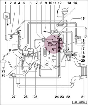 |
1-EVAP canister
2-From fuel tank
3-Evaporative Emission (EVAP) canister purge regulator valve -N80-
4-Check-valve for EVAP canister
5-Air cleaner
6-Turbocharger
Check boost pressure page 21-46
7-Combination valve for secondary air injection (AIR)
8-Fuel pressure regulator
9-To power brake booster
10-Check valve
11-Vacuum booster
12-To Leak Detection Pump (LDP)
13-Vacuum reservoir
14-Distributor piece
15-Check valve
16-Secondary Air Injection (AIR) solenoid valve -N112-
17-Crankcase vent
18-Check valve
19-To tank Leak Detection Pump (LDP) -V144-
20-Check valve
21-Charge air cooler
22-Throttle valve control module -J338-
23-Recirculating valve for turbocharger -N249-
Checking page 21-40
24-Intake manifold
25-Pressure unit for boost pressure regulation
26-Wastegate bypass regulator valve -N75-
27-Mechanical recirculation valve
28-Pressure control valve for crankcase ventilation
29-Secondary Air Injection (AIR) pump motor -V101- |
 |
Here is the kit, it includes:
1. Boost Brain with Power and Ribbon Cable
2. LED display board
3. A bunch of crimp clamps
4. A 5/32" T Connector
I recommend buying extra black 1/8" width zip ties
|
| |
Step 1. Remove the Knee Bolster:
There are four 8mm bolts to be removed. You can only see bolt #1
without removing trim pieces. Remove the two trim pieces to expose
bolts 2 and 3 with a flathead screwdriver. Remove the fusebox cover
with a flathead screwdriver to access bolt #4.
Once the bolts have been removed pull the knee bolster straight toward
the driver seat. There are two cables connect, one is for a light
and the other is for the VAG interface. Once you pull the knee bolster
off, it is easy to disconnect these cables.
|
| |
|

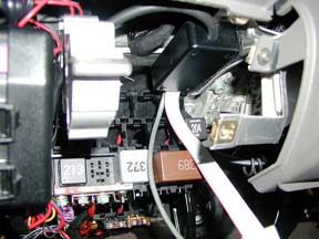
Picture of the mid-engine firewall.
|
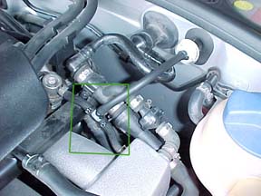
Step 2 Run Boost Line:
I apologize for the blurry pic. To run the boost line is pretty
easy. I have a 99.5 A4 so my car has a mechanical accelerator.
1. Open hood and remove plastic cover above the battery and ECU.
2. Find the mid engine gasket shown in the picture to the left.
It is located slightly off center. There is a nipple of rubber
perfect for our boost line. Cut off the tip.
3. Run line from engine compartment to the battery compartment.
4a. In my 99.5 there are no additional gaskets in the firewall
to get the boost line to the passenger compartment. In the 2000+
MYs there is a gasket free that you should be able to see and use.
4b. For pre-2000 MY cars, you need to drill a hole in the firewall
or use the hood release cable gasket located next to the driverside fender.
See to the left. You can cut a hole to run the line through.
5. Hint: To run the hose I stuck a nail in the tip of the
hose to reinforce/stiffen it. I fed in about 1-2 feet of hose then
guided it into the passenger area with a bent hanger.
6. Apply silicon caulk to any rubber gasket you cut.
|
 |
Step 3 Where to mount the brain:
There are a few options here and again this is personal preference.
I spent about 20 minutes trying different locations. In the end
I affixed via Zip ties and Velcro, the brain to the steering support structure.
1. Attach boost hose to "the brain". If you want
open the box and attach the boost line, then zip tie the connection and
trim. I did not as the connection was tight enough.
I tested the connection up to 30 psi without the hose coming loose.
|
 |
Step 4 Run Power Line:
1. Run power cable through the hole already (see photo).
2. Attach ground wire to a grounding bolt. Aground bolt is
any bolt that is connected to a metal bulkhead/chassis component.
There is one at the bottom of the fuse box.
3. Attach the power line to a 15 amp circuit. I recommend
a non-critical circuit such the cigarette lighter. See owners manual
for the associated fuse.
|
|

|
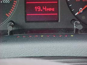
Step 5 LED display:
There are many different possibilities for mounting, Will chose to put
his on the dash by the A pillar. It worked nicely as a HUD gauge.
It reflects off the windshield. I chose to drill into the plastic
cover.
|
 |
Step 6 T connector splice:
Here comes the scary part. The one where you cut a hose on your
engine. I recommend using wire snips.
1. Finish running the boost hose, by zip tying the hose to neighboring
hardware, hoses etc. Be sure not to kink, or make hard corners
with the hose as this will restrict flow.
2. Pull the excess line through. Trim the hose making sure
you leave yourself a few extra inches of hose.
3. Cut the Fuel regulator hose. Place a clamp along each
hose segment. Insert T connector. Move clamps up. Using
an vise, electric, or other wrench, crimp the connectors.
4. An alternate is to tie into the hose opposite from this one,
closest to the other edge of the manifold. It runs to the BPV, and can
help in detecting problems with the valve.
|
| |
Step 7 You are DONE!!
1. Reassemble your car, aka the knee bolster and engine compartment.
2. Take your car for a drive and enjoy.
3. Don't keep flooring it to make all the pretty lights to come
on. TRUST me my fuel economy dropped 4 mpg =)
|
| If you have any questions, feel free to e-mail me at: |
ed@palisoc.net |