|
|
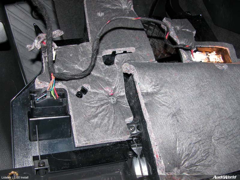
Be careful as you lower the panel so you don't damage the wire ECU diagnostic connector. Disconnect the two harnesses and set the knee panel aside.
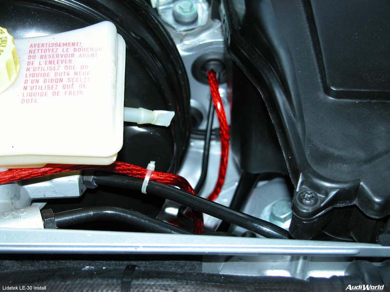
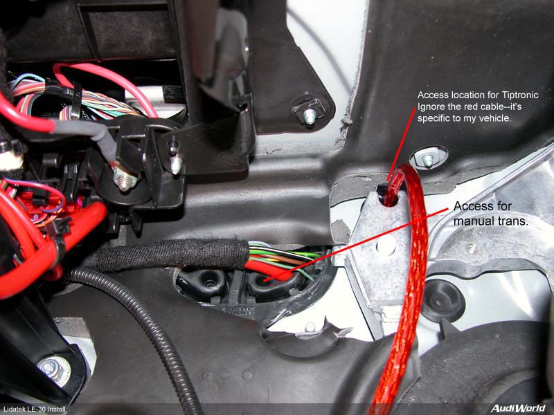
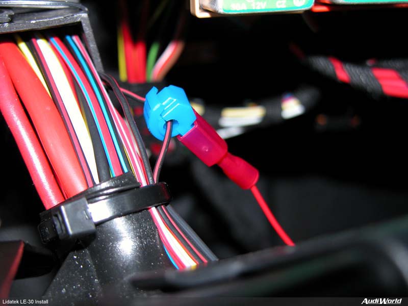
Route the cable through the firewall. On Tiptronic cars there's an unused grommet that is easily accessible right between the brake booster and the ECU box (left picture). Poke a hole through the grommet and insert the cable through it. It's more difficult on manual transmission vehicles as the grommets are harder to reach (the one shown for Tiptronic cars is not available). It's easiest to work from the inside with a manual transmission. Push some spare wire through then use it to guide/pull the harness through. If you use the grommet in the picture on the right the wire will come out right under the ECU box. It's a pain to reach but it's doable. Alternatively, the wire can be routed through the ECU box as the bottom is open directly into the passenger compartment. Next, connecting to power. Remove the two bolts that hold the fuse box. Drop it down and gently open the back by releasing the two lock tabs.
Looking at the fuse box in it's normal position, the top right fuse (should be a small 5A fuse) is switched power. It's a black/red pair of wires. Follow the pair of wires out of the fuse box case an and connect into one of the wires with supplied power tap. Close up the fuse box and put it back in. Secure the ground wire for the LE-30 under the top bolt for the fuse box. With double-sided tape, mount the speaker on a flat surface under the dashboard. I mounted the power switch with double-sided tape right above the fuse box. If you wish, you can use a bracket or drill a hole for it. It's such a small switch I didn't bother. The LE-30 comes with a status LED. I opted not to install the LED as the beeping speaker tells me all I need to know (based on my experience with the LE-20). If you wish to mount the LED two easy locations are available
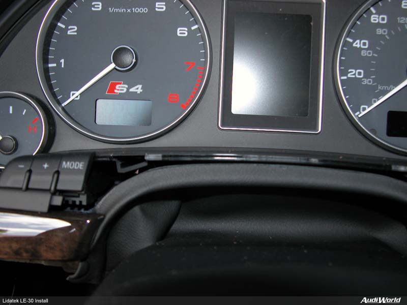
The trim at the bottom if the instrument cluster pulls straight out. Drill the correct size hole and route the wire. Nice and tidy. Or...
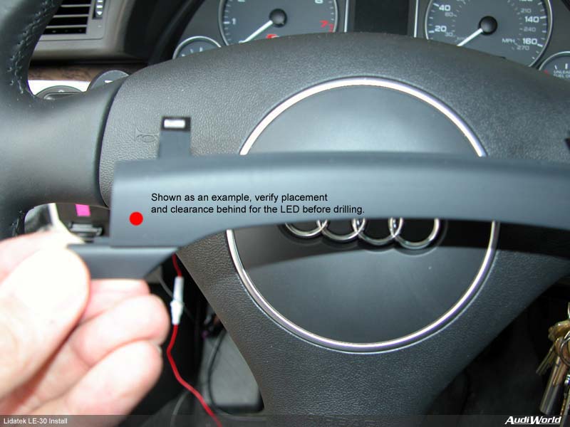
Pop out a spare switch cover if you have one (use a small screwdriver from the top), drill a hole and route wire. With the lower panel already removed, reaching behind the dash to grab the wire is a snap.
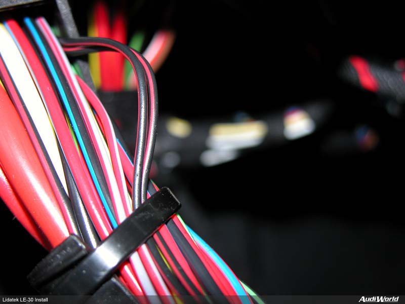
Gather up all your wiring and plug the connectors into the interface box. The first transponder goes into T1. Second, if so equipped, T2. R1 is for a rear transponder. Far right connector is for the LED. The connection between the power and speaker plug is not used at this time.
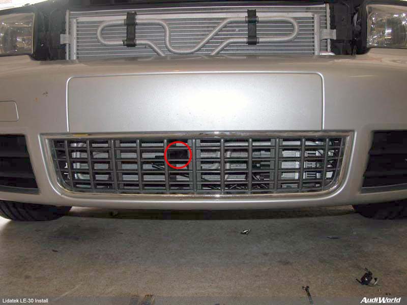
Attach the interface box to the back of the metal knee pad reinforcement. Tidy up and secure your wiring both inside and out with the supplied zip ties. Make sure the wires won't interfere with anything. Power up the system. The system will chirp once and then beep once for each installed transducer. Reinstall the lower knee panel (don't forget the wiring harnesses on the panel) and the fuse panel cover. The knee panel slips into a guide at the rear of the panel for support--be sure it's in correctly. Put the engine covers back on, weatherstrip and the front grill. Completed install. Enjoy! [1][2] |
|
Advertising |
Contact Us |
Cookie Policy |
Privacy Statement |
Terms of Service |
Do Not Sell My Personal Information
© 2020 MH Sub I, LLC dba Internet Brands |