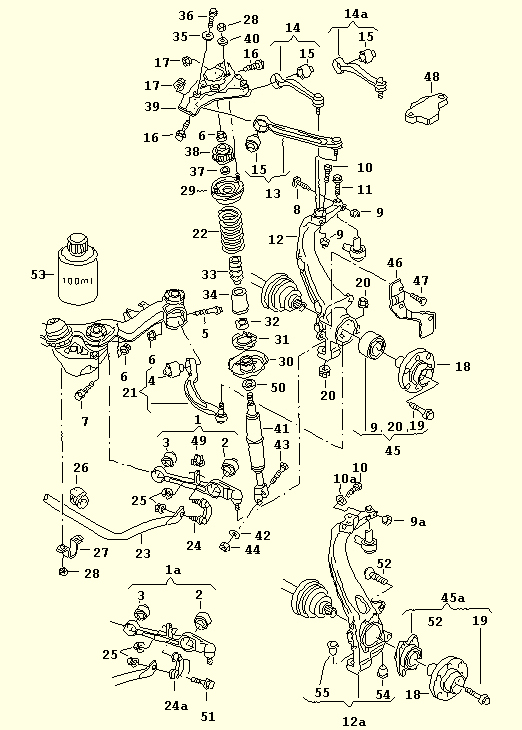
The parts book diagram showing all the front suspension parts.
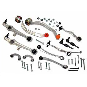
A Complete control arm set with NEW BOLTS and TRE's (Tie Rod Ends)!
Yay, get ready for some work!
So your control arms are shot and your ride sounds like a 1930's Ford that squeaks all over. No problem, if the squeaking are your control arms then here is your write-up to replace them.
It is a good idea to replace the TRE's as well when you this as an alignment is a very good idea after ANY suspension related work. With new TRE's and CA's you wouldn't have to go back to the shop to get an alignment down the road when you replace either one.
Here is Chris Haigh's write-up on how to replace the TRE. Go by his write-up on how to remove and replace the TRE's and use mine for the control arms. Most Control Arm sets will cost around 500$, you get what you pay for so watch out for those 200$ sets on eBay. After all it's the suspension that keeps your tuned and personalized car on the road.
Your Control arms need replacement anyways if the boot looks like this which is torn up and fluffy.
Here are some other ways to check which arm is clunking.
1) Jack car up on side that's clunking.
2) Do not remove wheel. Make sure steering rack is locked (ie key out of ignition, and turn steering wheel to lock it)
3) Grab the wheel by the 9 and 3 positions and wiggle it back and forth as it would turn by the steering. See if there is any play - there should be basically none. If you do have play, look at your control arms and feel around to see if anything is clunking or moving excessively.
Click here for a video of this test.
Click here for a video of a test for lower control arms.
In case you need to get the "knuckle assembly" aka wheel bearing housing out for a wheel bearing repair this should guide you to the removal of that as well.
Enough for the stuff here is what you need:
Breaker bar + extension if needed
17mm hex or smaller bigger depending on your year for the axle bolt
Ball joint removal tool
Set of wrenches
Maybe some air tools
Pb blaster or any other bolt rust breaker spray
Torque wrench
Basically a good garage should have all of the above and maybe even more
Here we go:
I am writing this guide several months after I had done the actual work. There might be some steps missing or not pictured as some of the stuff is a basic unbolt and bolt back on.
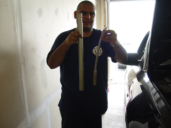
1. In order for the whole knuckle assembly to come out you need to loosen up the axle bolt that is attached to the CV boot. Its either 17mm hex (allen) or 24mm head bolt. Check that one out before you start and get the right size tool. That thing is in there TIGHT so an extension might be a very good idea as shown here:

2. Get your vehicle on JACKSTANDS not a floor jack, to many people had been injured and or killed without the use of stands. Invest 20$ in a set of them, they are cheap and safer than the hydraulic jack an article by Andy on where to jack up your car can be found here
3. Remove the wheels on both sides to expose the complete front suspension assembly.
4. Follow the previously mentioned TRE article to remove the TRE http://www.audiworld.com/tech/wheel29.shtml
I had some problems with the passenger side and ended up taking mine to the shop to get it removed. Here is what I ran into when doing my TRE
5. The front should look like this now with the TRE removed:

6. Since you will take out the complete front suspension you will should remove the brake disc and caliper as well.

In case you want to pain the caliper this is the perfect time for that as well. There are write-ups on how to remove the front brakes but here is a quick refresher.
Caliper is held onto the bracket with 2 hex bolts
Caliper is held onto the knuckle with 2 17mm IIRC bolts which are tight on there.
Brake disc is loosely held onto the knuckle with the caliper bracket, once that is loose you should be able to remove the disc. In case the disc is stuck due to rust tap it slightly with a hammer and a screwdriver like a chisel, it should come of that way.

Inspect your brake hoses for any cracking or damage, if you find some REPLACE THEM IN PAIRS! Otherwise hang the caliper now somewhere with a zip tie or have an old flowerpot of box to rest it on the ground. Don't let the caliper hang by the brake hose alone.

This is a good idea.
7. The next item on the list is the so called pinch bolt holding the upper control arms to the knuckle.

A close up

This bolt has been an issue with a lot of people to remove. If your car had been exposed to salty winter roads you will most likely have some issues removing it. I had no issues removing it but spray it with Pb blaster and follow Carson's idea as well:
/quote: Hitting the area around the pinch bolt with a hammer to loosen it up helps (read the directions on the can of PB, useful info)
You can also try turning the pinch bolt with a wrench after you get the nut off the end of it, it will either break the bolt loose or twist the head off the bolt, if it starts to twist stop what you're doing immediately. From experience, most of the time when I have to remove the pinch bolt from a steel wheel bearing housing I gotta haul out my HD Snap-On air hammer./end quote
8. After the pinch bolt is loose remove the upper control arms from the knuckle, they are just "pushed" in. With road salt and dirt in them they could be very had to remove so a tool like this might be helpful:
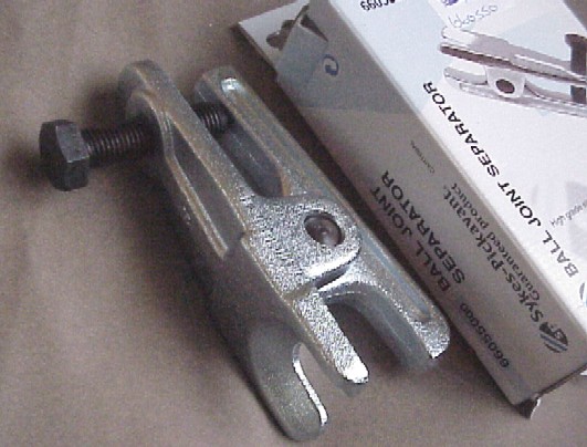
These are ball joint separators and range from 11$ to 100$ in price, you get what you pay for in quality. Your local car place might have them for rent as well.
9. Now its time to loosen that tight axle bolt up some more. When I did the work on Kevin's car I forgot to loosen them up with the car on the ground. I ended up breaking the bolt loose in the air and bended the breaker bar pretty good. So don't forget to loosen that bolt up before you lift the car into the air! Here are our results:

10. With the bolt loose. Tap it slightly with a hammer to "push" the whole CV joint out of the knuckle. I turned the bolt a like 2 turns, tapped it with hammer back to the bearing and turned again and so on... be gentle as the wheel bearing sits in the knuckle assembly. Depending on the mileage that you have on the car it's a good idea to replace both bearings as well since those are known to fail at some point and time.
You should be here now:

The knuckle is still connected to the car by the lower control arms while everything up top is loose and removed.
11. The upper control arms are attached to the strut mounting plate and we were unable to remove the bolts because of tightness, we ended up removing the plate. It's attached with 3 bolts as shown here:

Remove those bolts and the top will become loose. In order to take the strut tower out you will have to remove the lower bolt that is attached to the control arm. Also be very careful to not over torque those when you reinstall the whole thing.
The upper control arms showing some damage on the boots when we wedge something in there to remove them.
Remove the old arms either on the car or on the mounting plate.
12. Here is a picture of the lower control arm assembly connected to the knuckle. Now comes the removal of the ABS sensor (already loose in the 1st picture) if you want to. The abs sensor does NOT have to be removed but it's a good idea of cleaning it while you in here All that is needed is to disconnect the sensor cable.


In the top picture it shows the ABS sensor already removed. The abs sensor is just "pushed" into the whole where it sits the rest of its live and gets exposed to rust so it might be a bit hard to remove, but ours just pulled right out.
The connector for the sensor is stashed behind the fender well as seen here:

There is a rubber plug that you need to pull out, when doing so you will expose the connector, disconnect it and tuck it somewhere into the top of the control arms as shown.
13.The only thing that is holding the knuckle now to the car are all the lower bolts from the control arms and the reversed C sway bar link and the strut/suspension.

The rear control arm goes in from the top while the front control arm is pushed into the knuckle from the bottom. The reversed C is the sway bar link and connects to the control arm. Those are basic unbolt and removal steps now.
That is how the arms will look with the knuckle removed

You might need to use the joint tool again as the lower arms might be even tighter than the uppers. I had no issues with either, but this tool with be a life saver!
Unbolt those and take the knuckle assembly out

14. If you went the way that we did you car will look like this now:


15. In case you cant get one of the bolts out and you are stuck like this:

You will need to loosen up the green circled plate holding the sub frame on the side. No need to totally remove me but loosening it up will give you enough clearance to remove the bolt.

We loosened our bolt barely an inch and it worked

Remove lower front and lower rear control arms you complete the removal of all the control arms

that is it! Reinstallation in the reverse order!

Couple of notes in the end:
While doing this you can do several things:
Repaint Calipers
Change out brake hoses to stainless steel ones
Change out brake pads and rotor
Upgrade the front brakes to A8 rotors and TT carriers
Spray paint the whole fender well BLACK again while everything is removed for a cleaner look
Flush your brake fluid out
Oil change
Engine mount replacement
DV replacement
Just to mention a few things!
Torque Specs for reassembly:
Kevin always get on me for not using a torque wrench so here are the specs taken from Bentley Manual
Upper front; 50 Nm + 1/4 turn into mounting bracket
Upper rear; 50Nm + 1/4 turn into mounting bracket
Upper pinch bolt; 40 Nm (not TRE pinch bolt)
Lower front; 80 Nm + 1/4 turn into subframe
Lower rear; 90 Nm +1/4 turn into subframe
Lower control arms into steering knuckle; 100 Nm
Mounting bracket (shock tower assembly)
Upper bolts from inside the engine bay; 75 Nm
Lower nut and bolt into control arm; 90 Nm
Sway bar end link;
Lower connection to the sway bar; 100 Nm
Upper connection into the control arm; 40 Nm + 1/4 turn
Rear Sub Frame; Large Bolt 110 Nm + 1/4 turn small bolts; 23 Nm
A few tips for the reassembly. Don't torque down your new control arms "dry" that means without being attached to the knuckle assembly when reinstalling. Doing so will make it hard to move them around as needed.
USE antiseize on the following parts: Pinch bolt, TRE threads and the bolt holding the TRE into the knuckle.
CPP has a set of full metal suspension parts that are likely to last a whole lot longer than anything else. Their website with all the information except prices is here
Kris Hansen added grease fittings to his arms in terms of long term life. He has those included in his Upper Control arm write-up found on his website
Passatworld (VW Passat and the Audi A4 are basically the same mechanically) has a small Control Arm Faq that is Listed on the website
There is an active recall on the front lower control arm that will be replaced for free if certain conditions are met found Under this post
Thanks go out again to all the people whose pics have been used.