|
|
After years of use, many cars AM/FM reception quality starts to suffer. In my case, I could get no AM stations and only a few nearby FM stations, which often faded in an out. The problem is the rear AM/FM antenna booster located in the rear headliner just above the rear glass. Plastic molded on the circuit board cracks from heating/cooling in the car and pulls surface mount components up off the board. The board is designed to select the strongest signal from 3 antennas on the rear glass. One option is to replace the part, (# 8E5 035 225 D) but it will often break again and it is expensive. (~$250). Here’s a quick and nearly free way to restore reception quality. You will lose the diversity function, as you will only use one of the antennas, but in my case FM reception turned out to be just fine. AM reception was also improved. Note that if you live in a city with many tall buildings, where multi-path is a problem, you might want the diversity feature that the circuit board provides. Tools required: Soldering iron / solder, wire strippers, needle-nose pliers, liquid electrical tape Step 1. Remove the rear headliner. There are 5 clips across the front. Just pull down to remove. If one falls out of the headliner, just re-insert it for later.  Step 2. Disconnect the three connectors on the right and the ground connector in the center of the PCB board. Remove the PCB board (it is held in with 6 clips). This will reveal several contact pads on the glass.  Step 3. You will need to re-use one of the three connectors on the edge of the board. You can see my board with the plastic cracked below.  Turn the board over and remove the plastic covering where the connectors are soldered to the board. Each connector has 5 pins. Using your soldering iron, heat up the pins while pulling the connector away from the board. This may take some time to free the pins from the board. 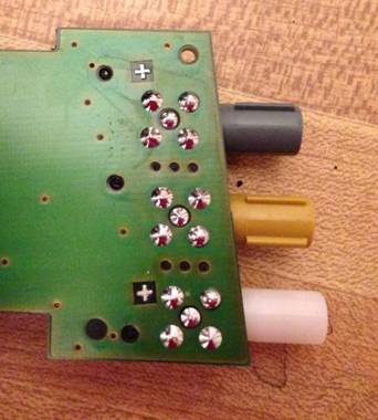 Step 4. With the connector removed, solder two wires to the pins. One wire (the antenna connection) should go to the center pin. The other pins are ground, and any of them can be used for the other wire. I bent the wires into a J shape to wrap around the pin. I used 22 gauge, solid conductor wire. The length should be about 8-12 inches.  I clipped the other ground pins to keep them out of the way.  Step 5. Put a glob of liquid electrical tape on top of the pins and along the wire. This will insulate the connection as well as provide strain relief. Let dry until hard.  Step 6. Choose antenna. Antenna 1 is a long wire running horizontally along the glass. Antenna 2 is in the top (not shown) and looks like a J. Antenna 3 is a L on the right. You can touch the antenna wire to each pad while listening to a weak radio station to see which you prefer. In my case Antenna 3 wasn’t great but the other two were about the same. At the same time you can optionally remove the ground wire using a Torx screwdriver so that it doesn’t rattle.  Step 7. Solder the antenna wire to your antenna of choice and the ground wire to one of the ground pads. Be careful here, these pads are very thin and too much heat will melt off the coating. I originally wanted to connect to Antenna 1 but ended up ruining it and couldn’t get a clean connection. I was able to connect to Antenna 2 by just briefly applying heat to the wire and the pad. I pre-coated the wire with solder. As an afterthought, a better way to do it would be to use the original circuit board which had spring connectors for the pads, and solder the wires to these spring connectors. 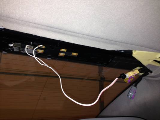 Step 8. Plug the connector into the yellow jack. The others you can leave floating. Tuck wires up and optionally use some tape to stick them up to keep them out of the way. Step 9. Check radio functionality and restore headliner by snapping it back into place.
|
|
Advertising |
Contact Us |
Cookie Policy |
Privacy Statement |
Terms of Service |
Do Not Sell My Personal Information
© 2020 MH Sub I, LLC dba Internet Brands |