When you click on links to various merchants on this site and make a purchase, this can result in this site earning a commission. Affiliate programs and affiliations include, but are not limited to, the eBay Partner Network.
I have successfully installed a custom PCV and catch can system, in my allroad, that is working great. Here is some of the what, how, and why:
First I removed all the SAIP stuff (secondary air injection pump). That crap just gets in the way. I got block off plates from ECS. I think there are posts somewhere on how to do this. Doing that didn't even throw a code on my car.
Here is what the stock PCV system looks like:
here is my schematic interpretation of the components:
After a lot of studying and some trial and error this is what I am using:
the directional arrows indicate vapor flow during throttle on conditions. Notice that it is two separate systems. One is the out gassing of the crankcase through the catch can and PCV into the intake manifold. The other is the in gassing from atmosphere air (nipple on the side of the "Y" pipe) into the valve covers. I think this set up is working really well. The piston blow by gasses get sucked out through the crankcase breather, to the catch can, then through the PCV valve, and into the intake manifold. Then, fresh air comes in from the valve covers, which get the air from the filtered atmosphere air from the "Y" pipe. I got the idea for this schematic from a GM aftermarket LS6 schematic. Two previous schematics that I used ended up not venting properly and led to horrific smoke from the tailpipes. This was from increased oil pressure in the turbos caused by positive crankcase pressure.
I should have taken some pics with the "Y" pipe off, but I didn't think of posting till later.
I used 1/2" and 3/8" oil hose, and black nylon plastic plumbing fittings (got them from USplastics)
I used a small two port Mishimoto oil catch can.
I'll explain the valve cover/ atmosphere run first:
Here's a pic at the passenger side valve cover:
In this picture I disconnected the electrical connector for the N75 valve so you can see the stock connector and pipe from the valve cover inlet to the fitting for the N75 valve tee. At that tee I connected 1/2" oil hose (it took a good deal of heat and twisting and pushing). From there the 1/2" hose bends toward the driver's side where it joins a 1/2" black nylon tee:
The hose on the passenger side of the tee came from the passenger side valve cover.
The hose on the top of the tee goes to the PRV and the "Y" pipe (atmosphere is what I call it, between MAF and TB):
The hose on the driver's side of the tee goes to the driver's side valve cover:
Again; heat gun and lots of twisting to get the 1/2" oil hose onto stock fitting.
Now for the crankcase breather, PCV, and catch can plumbing:
I have to explain some of it because I didn't take pics, sorry.
The crankcase breather is located under the intake manifold (see picture of stock PCV system, the lowest hose, in middle, went to this). It is like a snorkel that sits on top of the valley area between the heads. Just like the valve cover vents I used 1/2" ID oil hose that I attached to the stock connector fitting. From the fitting I used a 5" section of hose, then a 90 degree barb fitting and a section of hose to the catch can.
I used 3/8" ID oil hose for the catch can to intake manifold run. I figured their shouldn't be oil in it, so it shouldn't clog with oil sludge, so I could use thinner diameter, and also; the intake manifold connector fitting and PCV valve is a smaller diameter, and fit the 3/8" hose.
See the previous picture of the stock PCV system... Notice the central canister that all the tubes go to.... Notice the top middle tube and fitting. I used this fitting (just cut the plastic tubing off it with a knife). I also cut the PCV valve out of the tube near this fitting. Notice how this fitting angles toward the passenger side. I used a 5" long piece of 3/8" diameter oil hose on this fitting. Then I connected a 3/8" 90 degree angle hose barb fitting and angled it towards the driver's side and the catch can location.
From the 3/8" 90 degree fitting I attached in this order: 2" piece of 3/8" hose, PCV valve, then 3/8" hose to catch can.
here's a picture of these two hoses:
They are the ones right under the coolant res.
Here's a pic of the catch can:
That's an aftermarket fan control module on top of it (another story, maybe I'll post that project later).
Underneath the catch can is a drain, which consists of: npt barb fitting, 1/4" ID oil hose that I routed behind driver's side intercooler, and a simple shut off valve (in picture of plumbing parts)
I couldn't find any good DIY PCV valve-catch can posts when I started this project. It took a lot of studying and a couple mistakes before I got it right.
That's an aftermarket fan control module on top of it (another story, maybe I'll post that project later).
Thanks for sharing your project.
What piques my interest most right now is your aftermarket fan setup. I installed JH Motorsport's viscous fan replacement, and the wiring has never been 'right'. I'm only just now beginning to grasp what I'm dealing with�aside from very modest personal understanding of automotive electronics.
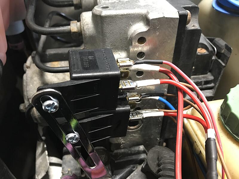
To my relatively untrained eye, it appears you have implemented two separate fuses and two separate relays for a two speed fan, presumably replacing the viscous fan. I could be mistaken about any and/or all of that, but a series on youtube about a project car in Australia being wired from scratch also caught my attention when they mentioned using two relays for a very powerful fan in the project car. Haven't made my way through all of it yet (Episode 1 of Dave's Wiring VLOG�videos that continue to enhance the electrical education of a newb like me), but among other things, it's inspired the vision of better outcomes in my own experience with my own installation.
At this point I'm unsure if there were pre-existing, and still present, problems in my car, but JHM's wiring setup for the fan seems a little wimpy for the fan�and might explain why I've witnessed two single relays in succession completely melt. I'm wide open to the possibility/likelihood that other problems remain to be discovered.
At the moment, coming out of winter, I have disconnected the entire setup, planning to re-engage the issue before summer heat arrives.
Would you be willing to comment, or share what you've done on your allroad? I'm sure there are others who may benefit from your experience.
Very nice solution and diagrams, that makes sense and looks like an improvement!
I'm not knowledgeable about the 2.7t but I'll share what I did with my cooling fans on my 12v V6: My cars previous owner removed the viscous clutch fan and installed a slimline electric fan, with some questionable wiring and relays. I initially went to install a Hayden controller, but the wiring colors weren't right and I couldn't get it to work.
Instead, I ended up using the temperature switch in the bottom of the radiator. That's what it is there for in the first place, so you can use it as the trigger for the relays. You have to make sure you get higher amp relays, and I personally ran fresh (and fused) power wire directly to the relays.
Here's mine. It's not exactly "finished" as I wanted some confirmation that it would work. But it's a heck of a lot better than what I started with:
Last edited by Victorymike18; 07-08-2021 at 12:20 PM.
Instead, I ended up using the temperature switch in the bottom of the radiator. That's what it is there for in the first place, so you can use it as the trigger for the relays. You have to make sure you get higher amp relays, and I personally ran fresh (and fused) power wire directly to the relays.
I, too, chose to purchase a Hayden controller, but abandoned it since they insist on using their own temperature probe, shoved through the radiator fins. Like you said, we already have a working temperature sensor in the bottom of the radiator, and I didn�t find their solution exactly elegant. Here�s what I ended up doing. The allroad has an expensive fan control unit for its fans, rather than a simple relay/relays. Two pair of very beefy wires come out of the fan control unit�one powers the passenger side fan behind the radiator; the other pair power a pre-radiator fan on the left (sitting in front of the JHM replacement for the viscous fan. I had wrestled around with how to wire this for quite awhile until it suddenly dawned on me I could remove the pre-radiator fan (which seems to be redundant), and run those wires used to power it directly to the Hayden two-speed fan behind the radiator, and so far, that�s working perfectly. I�m in New Mexico, and we�ve already had a fairly brutal heat wave here this year.
I keep my eye on the temperature gauge, and everything continues to work well. The passenger side fan seems to provide all the air conditioner needs to deal with torrid temperatures, and it�s working as it always has. The JHM fan is more powerful than the one previously in front of it, and now that it�s wired properly, there haven�t been any problems. As Albert Einstein reminds us, the simplest solution is usually to best choice. Unfortunately the human mind tends to be attracted to most complex solution.
This is, after all, a conversation about Audis and their owners....
You summed up my thoughts exactly about the Hayden unit. Between the temperature probe, and mine looking like it sat on a shelf for 10 years, I really wasn't impressed. Once I remembered that we have the temperature switch already, the decision was easy.
You mentioned the fan controller, and I completely forgot about that. My buddy DesertSage (user on here) was asking about that recently. Is it a silver box of some sort, located around the driver side front wheel area under the frame rail? My solution completely bypassed it, though I probably could (or should) have worked it in.
I agree, these cars can be over-complicated in many areas. Thankfully, the fans can be simplified.
That�s the one, Mike. I replaced mine, and can�t imagine trying to get to it without at least removing the oil filter (my choice, and it was still a job). Apparently it�s a piece of cake with the car in service position.
That’s the one, Mike. I replaced mine, and can’t imagine trying to get to it without at least removing the oil filter (my choice, and it was still a job). Apparently it’s a piece of cake with the car in service position.
Guys: notice the new pictures below. I added a second Hayden fan controller.
I did the work a while ago, but here is what I remember: My fan set up was also based on the JHM fan delete kit. It came with a Hayden fan controller that I powered with an 8 gauge power wire, with fuse, directly from the battery. The relays got very hot, as did the power lead, and one of the relays ended up failing. The good news is that I figured it would happen, so I had extra relays in my glove box. Since then I added a second controller to divide up the heat. I had done calculations which told me that the Hayden FC was just barely adequate to power the three fans (JHM two speed, and two stock electric units). To power the new FC I cut into the power supply for the stock FC (a very beefy wire, maybe 4 or 6 gauge) which was unused since adding the JHM kit. This way each FC has it's own power supply and now the power leads don't get nearly as hot, nor do the relays. I have it wired so that one FC runs the JHM fan, and the other runs the stock fans. The controllers have high and low speed, and have adjustment screws to set the actuation temperature. The JHM fan has wires for high and low speed, so fairly easy. I have set the low speed for the other controller to actuate the front fan. It is the one I have set to run when the climate control turns on (see JHM instructions for fan delete kit, or you can find the lead by using a test lamp or meter on one of the harnesses behind the driver's side headlamp). Also, I used a disconnect fitting for this wire. That way in the winter, I disconnect it, so the fan won't turn on just because I have turned on the climate control. I don't think I need to cool the AC condensor when it is -10 degrees. Also, I ran a disconnect for the AC compressor, from the wire for it, through the firewall, to the dash where I added a switch. I don't think the AC compressor needs to run when I have the heat on. I have the inner stock fan connected to the high speed lead. It is fairly complicated to understand. I drew a schematic for myself to make it easier and to keep track of all the wire colors. Also I used heavy duty disconnects for the power and ground leads for the fans, so that it will still be possible to put the car into "service position" (removing front bumper and radiator carrier assembly). I also added a small bolt to the body, right in front of the power steering reservoir for grounds. Other info: notice the little toggle switch, it is an override switch. I can turn the fans on manually with it. I also added a flimsy little heat shied to keep the relays a little cooler. This set up has been working quite well for me, and I don't have to worry about that plastic mechanical fan blade grenading and destroying my radiator. I'm glad I got a catch can with a drain on the bottom of it because it would be a pain to remove it just to drain it. My car has 200k miles on it, and still runs strong.
 03-13-2018, 06:13 PM