When you click on links to various merchants on this site and make a purchase, this can result in this site earning a commission. Affiliate programs and affiliations include, but are not limited to, the eBay Partner Network.
As I'm progressing through my dashcam install by taking off the necessary panels and tying wires together, I'm now at the electronic portion of the install. I'm trying to find an ACC fuse that is rated 15A or higher so that I can tap in the Cellink NEO. The Cellink NEO has a 9A charging input, which is why I'm looking for something rated 15A or higher. I've already checked the footwell fuse box and the driver-side fuse box and couldn't find one.
Additionally, I checked the empty slots in the footwell fuse box using a multi meter to see if I can use them, but it seems that the empty ones are truly empty (one side has a "positive" side with 12VDC, but there's no metal clip on the "negative" side to complete a fused circuit). I have a B9 A4 Premium Plus made for USA. Any electronic experts here that can help out?
While connecting a Power Magic Pro to the dead pedal fuses (something I gave up on because I was only getting 11.9V from any of the fuses with the engine off, which isn't enough to trip the circuit in the Power Magic Pro and provide power to the dash cam while parked), I think I figured out enough for you to connect an auxiliary battery. Because there seems to be a voltage drop between the battery and the dead pedal fuses, using an auxiliary battery is probably the only way to power a dash cam while parked with the engine off.
First, I don't think you have to tap any of the existing fuses, and you may be better off using one of the empty sockets so you don't alter the current going to something else. Second, I believe it would be easier not to use fuse taps and instead wrap a wire around the left leg of a new fuse and stick it into an empty socket, but I'll describe how to connect fuse taps anyway.
There are three banks of fuses on the top row, and from left to right they are switched/hot/hot. There are three banks of fuses on the bottom row and from left to right they are unknown/switched/hot. I needed one switched and one hot, so I tapped into the middle bank in the top row (hot or battery) and the middle bank in the second row (switched or accessory). In both cases, I used empty sockets, and I chose sockets where it would be easier to route the wires from the add-a-fuses because in order to get the add-a-fuse seated into its socket you will have to carve out a channel in the plastic slats that are beside the fuses. I used a Dremel with a multi-purpose cutting bit to carve away the plastic, which was a challenge because my clutch pedal was in the way. It would be easier with an automatic transmission. I believe that the add-a-fuses need to be inserted with the wire exiting to the left, not the right. You can read more about that here:
If you install the add-a-fuse with the wire exiting to the left, then you only need one fuse inserted in the add-a-fuse for it to work, but if you insert it the other way with the wire exiting to the right you need a fuse in each socket of the add-a-fuse. So I believe that proves that the correct orientation is how I show it below. With one hot and one switched add-a-fuse plugged into empty sockets, it looks like this (which actually powered my dash cam with the engine on and the alternator providing higher voltage than 11.9V):
You mentioned that the right hand side of each empty fuse socket is hot (or switched hot), but the left side is empty (i.e. no metal terminal). That's OK as long as you have a separate ground wire and connect it to a good grounding screw (I used a screw beside the dash fuse panel in the driver's door jamb because it was easier to access than the screw under the carpet to the right of the dead pedal). When you connect to an empty fuse socket, the power will come up through the right hand terminal, through the fuse, into your device and out through your ground wire.
So there are two reasons I think you should avoid using add-a-fuses even if you plug them into vacant sockets:
1. Add-a-fuses require you to cut away the slats between the fuse banks.
2. The add-a-fuses I used didn't fit tightly into the sockets.
If I were you, I would buy the appropriate amperage mini-fuse(s), wrap the wire you need to connect around the left leg of the fuse and plug into a vacant socket in the appropriate fuse bank. If you wrap the right hand leg with the wire, then you will be bypassing the fuse. You want to wrap the left leg so the current goes from the hot side, through the fuse and into the wire.
Thanks for the writeup! Only 11.9V? You must be in a really cold area or your battery is defective so you should go ask Audi to replace under warranty. Or, you can get a Celllink NEO like me I believe in the second bank of fuses, the lower left are relays, not fuses.
In the case of the Cellink NEO I'm trying to install, I just need one fuse that is switched that is rated for 15A (if unused) or 20A (if using add-a-fuse). I don't mind if I have to use an add-a-fuse, as I own a dremel to trim away the plastic. And yes, based on my research, the wire should be pointing left as shown in your pictures since the "hot" side is on the right.
I am curious to understand more of what you mean about wrapping a wire around the left leg of the fuse, and inserting that into an unused slot:
1. How would I know if the slot I'm using is rated for 15A? I'm assuming that behind the fuse box, Audi used thinner wires for the lower amp circuits, and thicker ones for higher amps.
2. If I wrap around the left leg and keep it exposed/unprotected, are there any dangers of shorting/arcing? Any way to protect the wire and prevent risk of electric fire?
3. What about ground? Are you suggesting that if I tie the ACC wire for the Celllink to the left leg of the fuse, current will feed through the Cellink and use the ground connection of the Cellink to complete the circuit?
Also,
If you install the add-a-fuse with the wire exiting to the left, then you only need one fuse inserted in the add-a-fuse for it to work, but if you insert it the other way with the wire exiting to the right you need a fuse in each socket of the add-a-fuse. So I believe that proves that the correct orientation is how I show it below. With one hot and one switched add-a-fuse plugged into empty sockets, it looks like this (which actually powered my dash cam with the engine on and the alternator providing higher voltage than 11.9V):
The wire should always be pointing to the left, never right, since the "hot" side is on the right. You would still need 2 fuses if you're actually adding a fuse, not tapping into an unused fuse. If you are tapping an unused fuse with 2 fuses and you have the wire pointing to the right, you're essentially killing two fuses with one short circuit (2 birds 1 stone reference).
While connecting a Power Magic Pro to the dead pedal fuses (something I gave up on because I was only getting 11.9V from any of the fuses with the engine off, which isn't enough to trip the circuit in the Power Magic Pro and provide power to the dash cam while parked), I think I figured out enough for you to connect an auxiliary battery. Because there seems to be a voltage drop between the battery and the dead pedal fuses, using an auxiliary battery is probably the only way to power a dash cam while parked with the engine off.
First, I don't think you have to tap any of the existing fuses, and you may be better off using one of the empty sockets so you don't alter the current going to something else. Second, I believe it would be easier not to use fuse taps and instead wrap a wire around the left leg of a new fuse and stick it into an empty socket, but I'll describe how to connect fuse taps anyway.
There are three banks of fuses on the top row, and from left to right they are switched/hot/hot. There are three banks of fuses on the bottom row and from left to right they are unknown/switched/hot. I needed one switched and one hot, so I tapped into the middle bank in the top row (hot or battery) and the middle bank in the second row (switched or accessory). In both cases, I used empty sockets, and I chose sockets where it would be easier to route the wires from the add-a-fuses because in order to get the add-a-fuse seated into its socket you will have to carve out a channel in the plastic slats that are beside the fuses. I used a Dremel with a multi-purpose cutting bit to carve away the plastic, which was a challenge because my clutch pedal was in the way. It would be easier with an automatic transmission. I believe that the add-a-fuses need to be inserted with the wire exiting to the left, not the right. You can read more about that here:
If you install the add-a-fuse with the wire exiting to the left, then you only need one fuse inserted in the add-a-fuse for it to work, but if you insert it the other way with the wire exiting to the right you need a fuse in each socket of the add-a-fuse. So I believe that proves that the correct orientation is how I show it below. With one hot and one switched add-a-fuse plugged into empty sockets, it looks like this (which actually powered my dash cam with the engine on and the alternator providing higher voltage than 11.9V):
You mentioned that the right hand side of each empty fuse socket is hot (or switched hot), but the left side is empty (i.e. no metal terminal). That's OK as long as you have a separate ground wire and connect it to a good grounding screw (I used a screw beside the dash fuse panel in the driver's door jamb because it was easier to access than the screw under the carpet to the right of the dead pedal). When you connect to an empty fuse socket, the power will come up through the right hand terminal, through the fuse, into your device and out through your ground wire.
So there are two reasons I think you should avoid using add-a-fuses even if you plug them into vacant sockets:
1. Add-a-fuses require you to cut away the slats between the fuse banks.
2. The add-a-fuses I used didn't fit tightly into the sockets.
If I were you, I would buy the appropriate amperage mini-fuse(s), wrap the wire you need to connect around the left leg of the fuse and plug into a vacant socket in the appropriate fuse bank. If you wrap the right hand leg with the wire, then you will be bypassing the fuse. You want to wrap the left leg so the current goes from the hot side, through the fuse and into the wire.
I have a Blackvue DR-750S connect to my car via a PMP and it keeps running all weekend without using the car. I had issues at first, when the PMP was set to 12.5V but the installer came back and reset it to 12v and now it is ok. Also connected into the fuse box behind the left hand panel. I tend to use time lapse instead of parking mode as it was going off all the time. The motion sensor being far to sensitive.
Disclaimer: I am not an electrician, so everything I'm stating in these posts is an opinion or pure speculation.
When I tested 11.9V at the fuse panel with the engine off, the battery terminals measured 12.1V, so there is roughly 0.2V drop between the battery and the fuse panel. Yes, I live in a cold area (averaging 20 degrees F over the last week), but my car is parked overnight in a heated garage and I charge the battery with an external charger about once per month. The last time I charged the battery was three days before I measured 11.9V at the fuse panel, and the charger tops the battery off to 13.0V. Based on my experience with an XC90 over the past few years, I think the low voltage problem in both cars (the XC90 suffers from this as well) is due to modern start/stop systems which continue operating until the battery's voltage drops below some minimum threshold and then disengages until the alternator has a chance to recharge the battery above some higher threshold. My A4's start/stop was still working with the battery at 12.1V, so it seems that Audi's start/stop voltage threshold is pretty low. I would be interested to know what cuke2u's driving profile is like - are you primarily driving in the city with lots of start/stops or on the highway with fewer start/stops and plenty of time for the alternator to recharge the battery? My driving is primarily city, so start/stop engages every couple of minutes. Note that cuke2u was having problems when his PMP was set for 12.5V, indicating that the voltage at his fuse panel was frequently below that threshold.
Regarding the amperage ratings of the empty fuse sockets - honestly I have no idea what they are rated for, but it doesn't make sense to me that these empty sockets would be rated differently than the sockets that are in use. It makes more sense that every socket within a bank of fuses is rated the same, because these fuse panels are probably manufactured for lots of VAG cars (and probably other makes as well). Wouldn't it make more sense to supply all of the sockets in the bank with the same gauge wire (or more likely a piece of metal that distributes power to all of them) so that the different makes/models have the flexibility to insert whatever amperage fuse is required for each circuit? That would also explain why low amperage circuits are grouped together and higher amperage circuits are in a different bank. If Audi went through the trouble of using different gauge wires to power each socket, why would they power all of them and what amperage would they assume for the empty ones? In any case, using the add-a-fuse in a socket that already has a fuse poses the same problem as using an empty socket - in either case you are assuming a certain amperage rating for the socket. Let's say you locate a switched 20A fuse and you want to install an add-a-fuse there. How do you know that the socket is rated for higher than 20A? Your auxiliary battery draws 9A and you will probably be adding a 15A fuse, so that socket with the 20A fuse should be rated for at least 35A to support the add-a-fuse. To me, it seems safer to assume that all sockets in a bank with at least one 15A fuse are rated for at least 15A (and use an empty one) than that a particular socket is rated for at least 35A when there are no other 35A or higher fuses in that bank.
Perhaps you should tap into an empty socket of the upper left (switched) bank of fuses because there are 15A circuits in that bank whereas in the second row middle (switched) bank the highest rated fuse is 10A. However, it looks like using an add-a-fuse in the upper left bank might be difficult with the wire exiting to the left (though you could just wrap a wire around a 15A fuse and fit it into an empty socket in this bank or put two 15A fuses into an add-a-fuse and plug it into an empty socket backwards with the wire exiting to the right).
I have not personally wrapped a wire around a fuse leg, but here is an excerpt from the PMP instructions that describe exactly that. I assume there would be a way to wrap it so that the exposed wire is fully seated in the socket and only the insulation is visible once the fuse is inserted.
Regarding the ground question - I haven't seen your auxiliary battery's wiring diagram, but yes, I believe that the ground wire from your auxiliary battery's wiring loom will complete the circuit from the hot (right) leg of the fuse panel socket, through the fuse, through the ACC wire, into your battery and out through the ground wire. The PMP wiring loom has a ground wire too, and I completed a circuit the same way (using an empty fuse socket with hot on the right side and no terminal on the left).
By the way, I spoke with someone from BlackBoxMyCar today about returning my Power Magic Pro because the voltage at my fuse panel is only 11.9V, and they had never heard of that problem before.
Question for deekay11 - if the battery draws 9A, why are you planning to use a 15A fuse? Wouldn't it be safer to use a 10A fuse? Does the manufacturer recommend 15A?
By the way, I spoke with someone from BlackBoxMyCar today about returning my Power Magic Pro because the voltage at my fuse panel is only 11.9V, and they had never heard of that problem before.
I would say I am not surprised, when I first had the PMP fitted it was constantly turning off the cam due to the voltage creeping below 12.5v. But now, once adjusted to 12v, it seems to keep going longer however it'll still power down when I come to the car unlock it.
I do rather feel that today's start stop batteries are actually designed to go below 12v on occasions without having any issues, thus i feel that PMP might be a little behind the times. Having said that if you are constantly getting a measurement of 11.9v then I would be concerned.
Question for deekay11 - if the battery draws 9A, why are you planning to use a 15A fuse? Wouldn't it be safer to use a 10A fuse? Does the manufacturer recommend 15A?
The input for the Celllink NEO is max 13.5A. I'm assuming that only happens if the car battery voltage is low, which is a concern if I keep the car parked for a long time while travelling for work/vacation. I'd want to prevent unnecessary blowing of fuse as much as possible.
Originally Posted by SDakota
And if you're interested in more comments about using an add-a-fuse vs. wrapping a wire around the leg of a fuse, you can read this thread:
Regarding the amperage ratings of the empty fuse sockets - honestly I have no idea what they are rated for, but it doesn't make sense to me that these empty sockets would be rated differently than the sockets that are in use. It makes more sense that every socket is rated the same, because these fuse panels are probably manufactured for lots of VAG cars (and probably other makes as well). Wouldn't it make more sense to supply all of the sockets with the same gauge wire (or more likely a piece of metal that distributes power to all of them) so that the different makes/models have the flexibility to insert whatever amperage fuse is required for each circuit? If Audi went through the trouble of using different gauge wires to power each socket, why would they power all of them and what amperage would they assume for the empty ones? In any case, using the add-a-fuse in a socket that already has a fuse poses the same problem as using an empty socket - in either case you are assuming a certain amperage rating for the socket. Let's say you locate a switched 20A fuse and you want to install an add-a-fuse there. How do you know that the socket is rated for higher than 20A? Your auxiliary battery draws 9A and you will probably be adding a 15A fuse, so that socket with the 20A fuse should be rated for at least 35A to support the add-a-fuse. To me, it seems safer to assume that all sockets are rated for at least 15A (and use an empty one) than that a particular socket is rated for at least 35A.
I think I saw a video where someone showed the back of an older Audi fuse box, and it seemed like there were different sized wires. I don't know if they were ground wires, but your logic makes sense where there is a rail that provides power (I checked with multimeter to confirm the whole row of fuses provides power). Although in my opinion, it makes sense they have different size wires, because thicker wires cost extra $, so to save costs I imagine Audi only used appropriate wires for its respective system without overengineering. Also, the point of the fuse is to prevent the wire from burning, not protecting a device/system, so if there is a 10A fuse, I'm guessing the wire will realistically handle 15A, and not 30A.
As far as your math of adding the amps, I think that's only when both systems will be running at full load, which "should" be rare. But you're right, I wouldn't know if the socket is rated higher than 20A if I were to tap that fuse. Either way, in the case of the add-a-fuse, if the amps go higher than the fuse rating, the respective fuse should blow to keep the wire behind the fuse box safe. At least, that's what I'm speculating
 12-09-2018, 03:07 PM


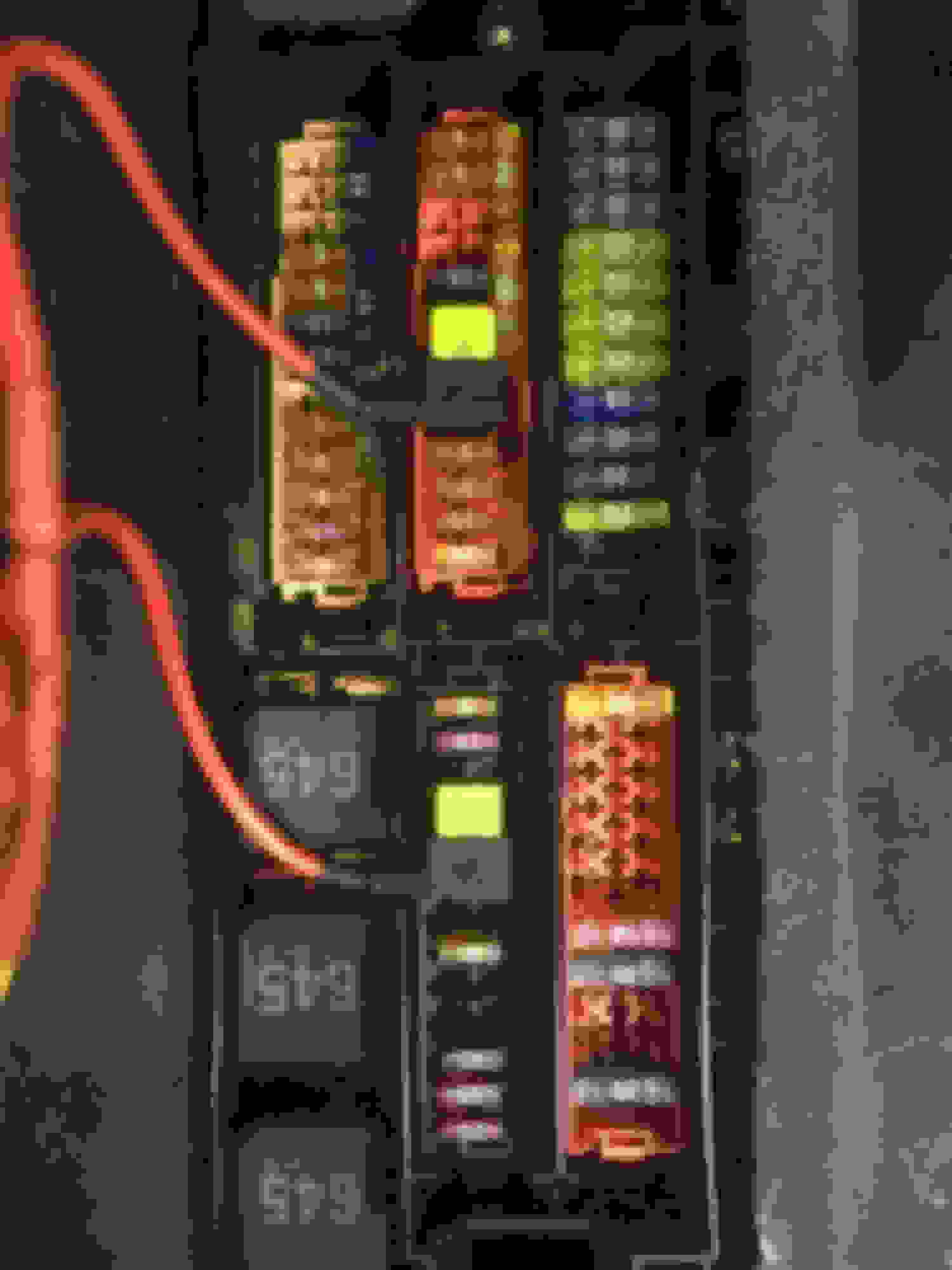

 I believe in the second bank of fuses, the lower left are relays, not fuses.