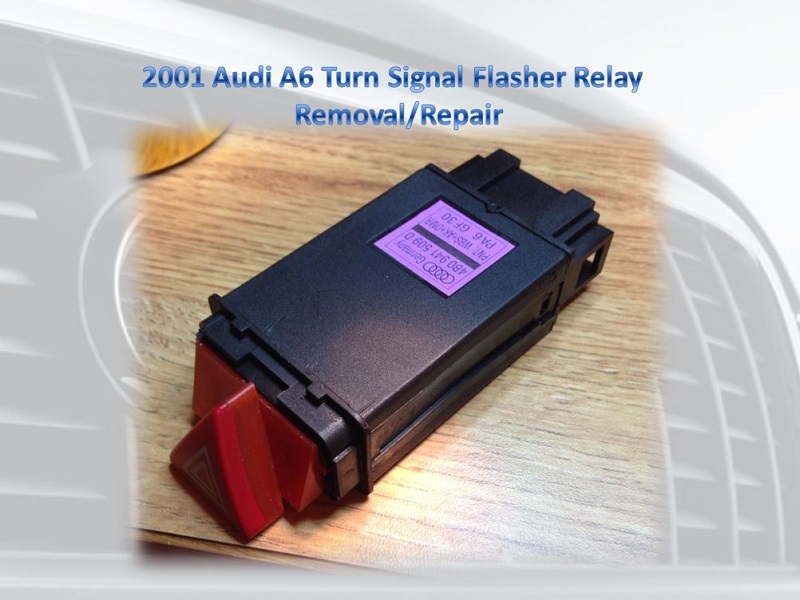
2001 A6 Blinker solid / Turn Signal Solid / Hazard Switch Repair
 05-24-2014, 11:30 AM
#1
AudiWorld Newcomer
Thread Starter

I have a 2001 A6. I repaired my blinkers by disassembling my hazard switch and removing and replacing the turn signal relay. The relay was encased and said "OMRON G8N-1". I found this relay from mouser.com and bought it for $10.30 plus shipping.
I made a Power Pont Presentation on the whole process that I went through. Hopefully this is helpful to those who might like to try to repair their hazard switches, before replacing them.
***Make sure you download the document, if you try to view it in media fire it doesn't come out right. The document is 12.33MB.***
2001 A6 Turn Signal Relay Repair
 05-26-2014, 11:12 AM
#2
AudiWorld Super User
Good Job . its nice to see someone contribute so much on their first post. i dont think having people download stuff to their computer is the right way to go though . Why not just attach a few pics to show what you did ?
05-26-2014, 01:12 PM
#3
AudiWorld Newcomer
Thread Starter
I converted the power point to a PDF. Hopefully this will be a better format for people. The PDF can be viewed and does not have to be downloaded if that makes people feel better. When I have more time I can post some pics with a write up.
Here is the link to the PDF version
Here is the link to the PDF version
05-26-2014, 02:31 PM
#4
AudiWorld Super User

Great presentation�.I think I would just buy a new one for about $45 plus shipping. But you did a beautiful repair job!
05-26-2014, 02:32 PM
#5
AudiWorld Super User
I'd like to see this in the tech articles section if only as a template for how a presentation SHOULD be done.
If you don't mind I sent it to staff@audiworld.com for that purpose, credit to MKnight002.
If you don't mind I sent it to staff@audiworld.com for that purpose, credit to MKnight002.
Last edited by SloopJohnB@mac.com; 05-26-2014 at 02:38 PM.
05-27-2014, 03:38 AM
#6
AudiWorld Newcomer
Thread Starter
Please use this presentation as you see fit!
I was going to make another on repairing the headlight switch (fog lights flickering on and off, and burnt out LED's). In the future should I just insert pics to a post? Or do another presentation like this one?
I was going to make another on repairing the headlight switch (fog lights flickering on and off, and burnt out LED's). In the future should I just insert pics to a post? Or do another presentation like this one?
05-27-2014, 03:46 AM
#7
AudiWorld Super User
"Welcome to the AudiWorld Tech section. Since 1996 we have written and collected articles containing specific information about do-it-yourself maintenance and other hard-to-find details.While we generate our own technical articles from time to time, AudiWorld Tech articles are generally based on the experiences of our readers. If you have performed specific upgrades or modifications to your Audi or have information that you believe should be shared with others, then you are strongly encouraged to submit that information for a Tech article. Submit articles by e-mailing to staff@audiworld.com"
Trending Topics
05-28-2014, 04:46 AM
#8
AudiWorld Newcomer
Thread Starter
I finally had time to pull pictures off the original presentation. It was suggested to me that this is the better way to go. The PDF and power point versions are still available at the links in my first posts.
BACKGROUND:
While driving to lunch one day I found that my blinkers suddenly stopped blinking and went solid. I confirmed this by getting out of the car and looking at the blinkers when engaged. They were solid for both left and right. I found a circuit diagram and found the flasher relay is integral to the hazard switch. Like so many of you do, I searched the forums and youtube for a fix. I confirmed the relay is in the hazard switch. After a few days of using the blinker switch manually to make the them blink, I suddenly found the blinkers quit coming on all together. CRAP! I thought maybe I broke the multifunction switch, but after �tapping� the dash a few times, the lights came back on solid. The blinker relay has died altogether. I found a �how to� on removing the hazard switch (too easy) and a video on how to disassemble the switch. The video was older version, and the relays were not encased. Mine are encased. I looked up how much a hazard switch would cost and found them to be from $25 (ebay) to $46 from various online stores. Being a �Do-it-Yourselfer� I decided to see if I could fix my hazard switch for cheaper, rather than buy a new one.
After it was all said and done I had spent $10.30 plus shipping, and the blinkers worked as designed.
DISCLAIMER: PERFORM THIS FIX AT YOUR OWN RISK. I AM NOT RESPOSIBLE IF YOU RUIN YOUR SWITCH (or car) PERMANENTLY. This was a fairly simple fix for me, but I do have some circuit board repair experience. I am not an expert at soldering, but I am not a beginner by any means. I also have an above average (self-proclaimed) understanding of wiring diagrams and circuits.
----------
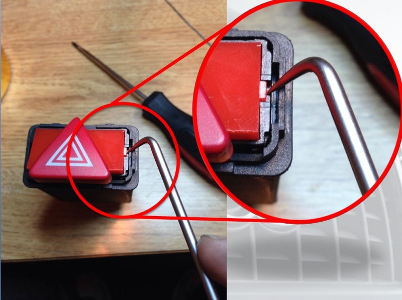
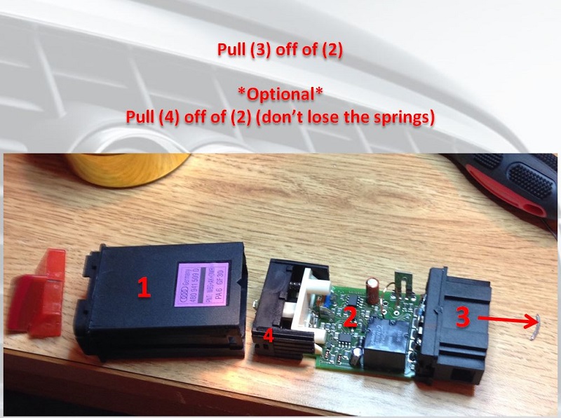
First you need to remove the red lens. One side is larger than the other, you can use a small screwdriver or a pick to pop the tabs on each side.
----------
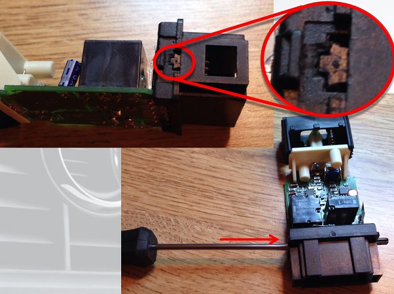
After red lens is removed, use a screwdriver to pop the tab shown, and repeat on the opposite side. Be careful not to break the tabs, they are very thin.
----------
----------
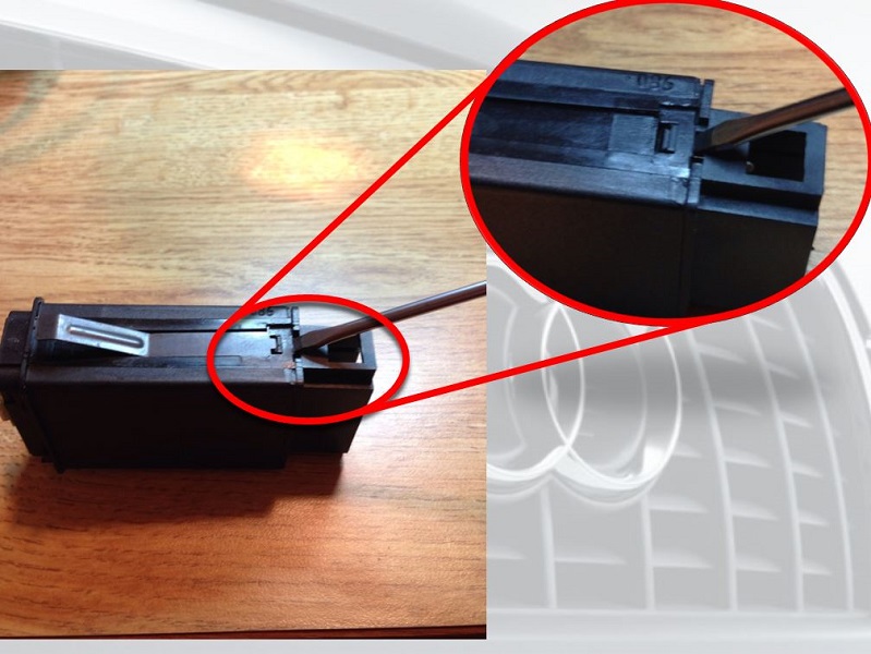
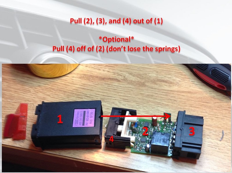
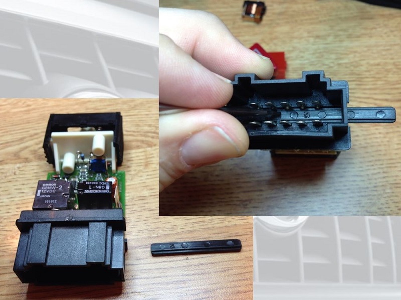
Remove the lock bar that holds the connector casing on the pins. Use a small screwdriver or pick to push through. You may be able to pull through at this point.
----------
The bar was in too tight for me to remove in the last step, so I inserted the screwdriver in the center and pushed it through.
----------
----------
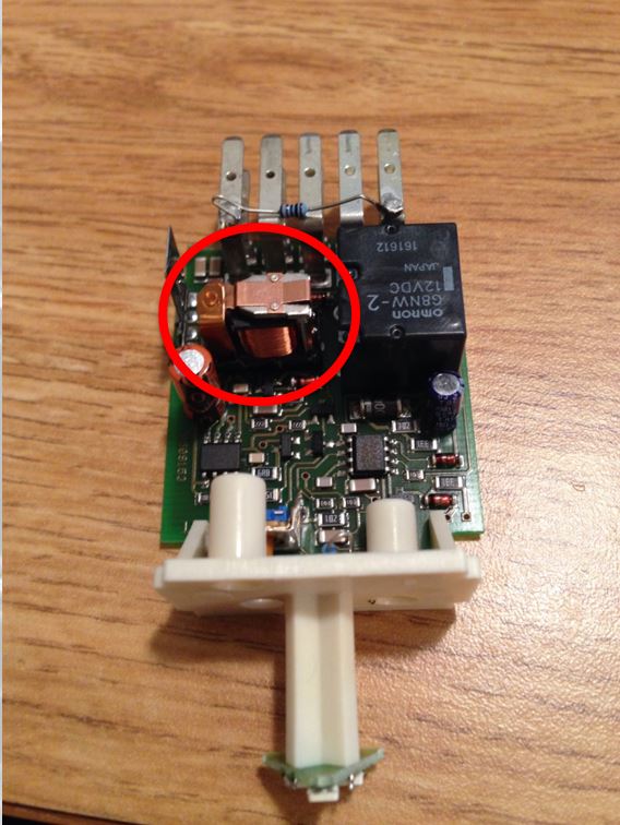
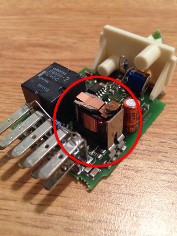
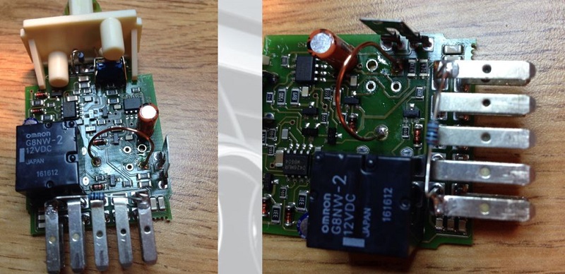
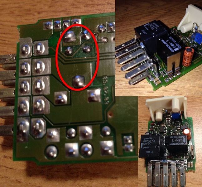
The circled relay is the turn signal flasher relay. It was encased like the one next to it, but I removed all the casing to check for corrosion. There was none so the relay just went bad. The casing was marked Omron G8N-1, after a little �Googling� I found that www.mouser.com sells a G8N-1. I ordered the relay with the hope that it would be the correct one. It cost $10.30 before shipping.
Until it arrives I decided to remove the relay and use a solid piece of wire to allow me to manually make the blinkers flash.
The other, bigger relay is the hazard flasher relay.
----------
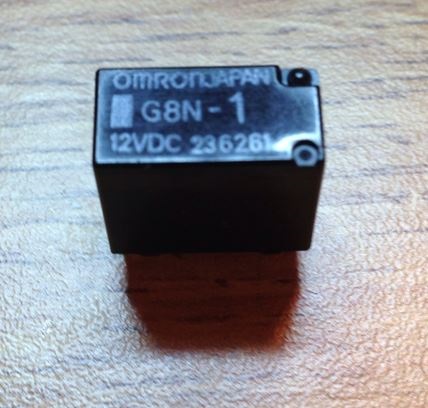
Omron G8N-1
Another view of the bad relay.
----------
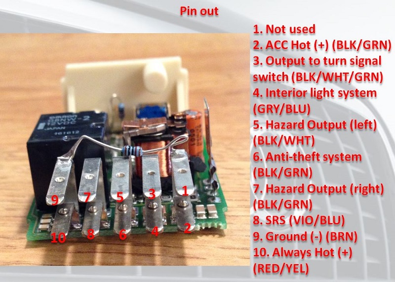
Hazard Switch Pin Out
----------
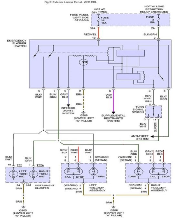
Hazard Switch Wiring Diagram (the quality is much better in the PDF version)
----------
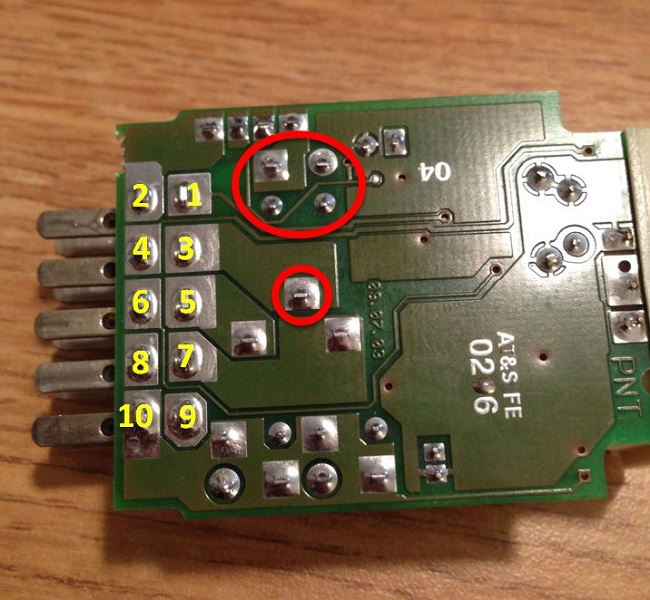
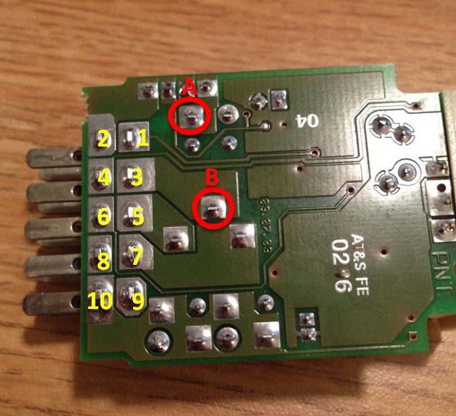
These 5 soldered points are the turn signal relay contacts. If you want to remove the relay you will have to heat these point up and de-solder them. The yellow numbers reflect where the connector pins are soldered to the board.
----------
Point A is the power input from the ACC +, point B is the power output when the relay is energized. These are the 2 points that I soldered a piece of solid wire between to allow power to be at the turn signal switch all the time.
***NOTE*** I did this because my relay was completely dead. If your relay is latching but not blinking this is not necessary for you. I do not recommend keeping this setup for an extended period of time. I don�t know the integrity of the piece of wire I used. Also using your blinker switch manually for a long period of time may cause premature failure of the multifunction switch .
----------
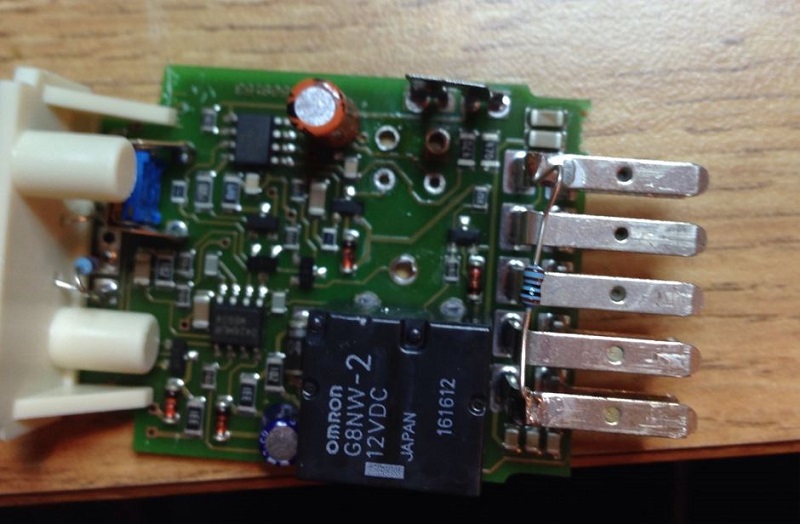
I soldered a piece solid wire between the 2 points to allow this circuit to be powered all the time. This allows me to use the turn signal switch to manually make the turn signals blink. This was a temporary fix until I receive my new relay.
***NOTE*** I did this because my relay was completely dead. If your relay is latching, but not blinking, this is not necessary for you. I do not recommend keeping this setup for an extended period of time. I don�t know the integrity of the piece of wire I used. Also using your blinker switch manually for a long period of time may cause premature failure of the multifunction switch .
----------
I ordered this relay from http://www.mouser.com/.
----------
As soon as the new relay arrived I removed the solid piece of wire and prepared for the new relay.
----------
Solder the new relay. Make sure all 5 points have good contact.
----------
At this point you are done. Re-assemble and try it out.

BACKGROUND:
While driving to lunch one day I found that my blinkers suddenly stopped blinking and went solid. I confirmed this by getting out of the car and looking at the blinkers when engaged. They were solid for both left and right. I found a circuit diagram and found the flasher relay is integral to the hazard switch. Like so many of you do, I searched the forums and youtube for a fix. I confirmed the relay is in the hazard switch. After a few days of using the blinker switch manually to make the them blink, I suddenly found the blinkers quit coming on all together. CRAP! I thought maybe I broke the multifunction switch, but after �tapping� the dash a few times, the lights came back on solid. The blinker relay has died altogether. I found a �how to� on removing the hazard switch (too easy) and a video on how to disassemble the switch. The video was older version, and the relays were not encased. Mine are encased. I looked up how much a hazard switch would cost and found them to be from $25 (ebay) to $46 from various online stores. Being a �Do-it-Yourselfer� I decided to see if I could fix my hazard switch for cheaper, rather than buy a new one.
After it was all said and done I had spent $10.30 plus shipping, and the blinkers worked as designed.
DISCLAIMER: PERFORM THIS FIX AT YOUR OWN RISK. I AM NOT RESPOSIBLE IF YOU RUIN YOUR SWITCH (or car) PERMANENTLY. This was a fairly simple fix for me, but I do have some circuit board repair experience. I am not an expert at soldering, but I am not a beginner by any means. I also have an above average (self-proclaimed) understanding of wiring diagrams and circuits.
----------
First you need to remove the red lens. One side is larger than the other, you can use a small screwdriver or a pick to pop the tabs on each side.

----------
After red lens is removed, use a screwdriver to pop the tab shown, and repeat on the opposite side. Be careful not to break the tabs, they are very thin.

----------

----------
Remove the lock bar that holds the connector casing on the pins. Use a small screwdriver or pick to push through. You may be able to pull through at this point.

----------
The bar was in too tight for me to remove in the last step, so I inserted the screwdriver in the center and pushed it through.

----------

----------
The circled relay is the turn signal flasher relay. It was encased like the one next to it, but I removed all the casing to check for corrosion. There was none so the relay just went bad. The casing was marked Omron G8N-1, after a little �Googling� I found that www.mouser.com sells a G8N-1. I ordered the relay with the hope that it would be the correct one. It cost $10.30 before shipping.
Until it arrives I decided to remove the relay and use a solid piece of wire to allow me to manually make the blinkers flash.
The other, bigger relay is the hazard flasher relay.

----------
Omron G8N-1
Another view of the bad relay.

----------
Hazard Switch Pin Out

----------
Hazard Switch Wiring Diagram (the quality is much better in the PDF version)

----------
These 5 soldered points are the turn signal relay contacts. If you want to remove the relay you will have to heat these point up and de-solder them. The yellow numbers reflect where the connector pins are soldered to the board.

----------
Point A is the power input from the ACC +, point B is the power output when the relay is energized. These are the 2 points that I soldered a piece of solid wire between to allow power to be at the turn signal switch all the time.
***NOTE*** I did this because my relay was completely dead. If your relay is latching but not blinking this is not necessary for you. I do not recommend keeping this setup for an extended period of time. I don�t know the integrity of the piece of wire I used. Also using your blinker switch manually for a long period of time may cause premature failure of the multifunction switch .

----------
I soldered a piece solid wire between the 2 points to allow this circuit to be powered all the time. This allows me to use the turn signal switch to manually make the turn signals blink. This was a temporary fix until I receive my new relay.
***NOTE*** I did this because my relay was completely dead. If your relay is latching, but not blinking, this is not necessary for you. I do not recommend keeping this setup for an extended period of time. I don�t know the integrity of the piece of wire I used. Also using your blinker switch manually for a long period of time may cause premature failure of the multifunction switch .

----------
I ordered this relay from http://www.mouser.com/.

----------
As soon as the new relay arrived I removed the solid piece of wire and prepared for the new relay.

----------
Solder the new relay. Make sure all 5 points have good contact.

----------
At this point you are done. Re-assemble and try it out.
The following users liked this post:
tgai (01-08-2021)
05-28-2014, 06:20 AM
#9
AudiWorld Super User
It really is an exceptional presentation�you could write for Bentley pubs but their editor would dumb it down to line drawings!
12-11-2021, 02:14 AM
#10
AudiWorld Junior Member

Join Date: Apr 2016
Location: Latvia, Jurmala
Posts: 26
Likes: 0
Received 0 Likes
on
0 Posts
Is it ok to cut of pin 10 (12v) wire and instead connect pin 2 with pin 10? working on;y when key is on? I have a large parasitic discharge thru hazard signal module, changet to new (chinese) came 2 times larger discharde. Its almost half of all car draw..

Thread
Thread Starter
Forum
Replies
Last Post
Audi_RKT....(Bedros)
A6 / S6 (C5 Platform) Discussion
6
11-03-2005 09:25 PM