When you click on links to various merchants on this site and make a purchase, this can result in this site earning a commission. Affiliate programs and affiliations include, but are not limited to, the eBay Partner Network.
My tech has removed, repaired and replaced the ZF 5HP-24A automatic transmission on one of my 2000 Audi A6 Quattro 4.2 V8 cars, and now the starter doesn't crank. It used to, before the festivities began. And no, we didn't remove and replace the engine as part of the work.
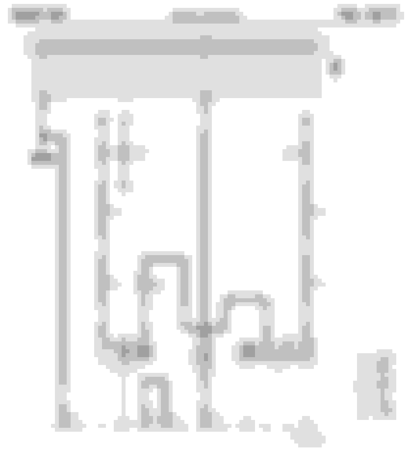
My guess is probably that the transmission "has to be in P or N to start" interlock is the problem but I'm trying to do better than guessing, so I've spent an hour or two staring at the wiring diagram on the electronic Bentley manual I bought, and wondering how to make sense of it all, including the page that's supposed to help me make sense of it all.
On this forum, the Bentley manual tends to be mentioned in the context where:
A. Someone is attempting a complex task and is asking not-so-bright questions to which the reply is sometimes "first, go buy a Bentley manual." I'm a computer geek and the advice "RTFM" was something that the guys often muttered in the Information Technology departments where I worked. Three of the letters refer to "Read the Manual" and the "F" is the first letter of an adjective.
B. Someone HAS bought the Bentley manual and announces it to be useless.
As an IT nerdy girl, I was often the only girl around, so when the boss asked who'd be willing to write the manual, I would always volunteer while the guys looked at me with gratitude but also like I was crazy.
One of the problems I have with manuals is that they tend to be written by people so savvy that they can't fathom the cluelessness of someone who needs a manual. So the best time to document something, it seems to me, is when the author is still clueless and can explain the problem situation well enough to where another clueless reader can relate. Then, on an intellectual journey, the author and the reader figure it out together.
Since I'm clueless as to how to read the Bentley manual and how to troubleshoot my non-cranking Audi, I qualify.
[If you know how to solve the problem please don't tell me yet; I'm trying to figure this out for myself like a 4-year old with an educational toy. But if you see a flaw in anything technical I'm writing here, then do please point it out to me.]
As context, I do understand troubleshooting and how to read wiring diagrams in the back of Haynes manuals. And when I was 20, I gave a friend a fixed bid on replacing his entire wiring harness, every piece of electrical wire in the entire 1972 Renault 16 TS. I'd quoted him $100 and it took me days and days to get it done, but I got it done, and done right. I learned a lot on that project, and electrics were the least of it. My point is that I'm specifically clueless but not generally clueless.
So, beginning with this diagram below, I didn't know how to start making sense of it. If you don't either, maybe this thread is for you.
I don't have Bentley's OK to post this. Since I make my living in the intellectual property field, I shouldn't be screwing people over as such, nor is this my intent. I'm hoping this is "fair use" and that more folks will buy Bentley manuals as a result of this post.
I'm used to seeing electricity flow in a sort of circle or rectangle, from positive to negative. So, I'm used to seeing a diagram with a plus and a negative in there somewhere and then I go trace from the positive through perhaps a fuse box and a couple of connectors and then there's the energy-consuming device, yay, and then down to ground with a little icon that looks like an old-school television roof antenna (indicating ground), done. Not so, in the Bentley manual. So, I couldn't even get started.
Gradually it dawned on me that this makes a lot more sense of I presume that positive is always at the top of the page, and ground a.k.a. negative is at the bottom. Aha! So, assuming that's valid, that's a good start.
**Edit: By reading more, I learned that he large block across the top is the fuse box or relay panel, and the numbered line at the bottom is chassis ground.
One funny thing I realized a few years ago while troubleshooting my 1984 BMW 318i is that the numbers on the wiring diagram have a lot in common with the numbers I saw on Mercedes-Benz wiring diagrams, and here's the Audi with, again, some very familiar looking numbers from many wiring diagrams I've seen: 30, 15, 31 ...
Looking at the "A" symbol, the battery, and it's positive side (at the top, aha, with negative being at the bottom, so yes, my premise is still holding water) the connection goes up to positive track 30. There's no switch. It's a direct connection. So, 30 is the perfect-girlfriend track (always positive, or if you prefer: always hot). So, now I have (and ideally, you as the reader, also have) learned something else: the 30 track is always positive. The 30 track spans multiple pages, powering multiple devices that require power to be on regardless of whether or not the ignition key is turned on.
The "hot when turned on" (the ignition key, I mean) track is either 31 or 15. I'm going to figure out which it is.
I'm starting with the circuit at the far left, from positive to component J31 and then to ground (number 2). J31 is the wiper/washer intermittent relay, it says at the bottom of the diagram that I can see but you can't, since I cut that off, sorry.) Even so, that's about as clean and simple as a circuit can get. So presumably, we would like the wiper/washer intermittent relay to be on only if the ignition is on, so I conclude that circuit 31 is when the ignition is on.
Circuit 15 is, as I recall, positive only when the ignition key is turned to the "start" position. it certainly wouldn't affect a wiper/washer intermittent relay, so more reason to think the "positive only when the ignition is on" track is number 31, not number 15. So far so good.
**Edit: By reading more, I learned that number 31 is a direct connection to ground, oops
So, as to the starter circuit: the battery (icon A) has three always-positive leads, one going to the alternator, one going to an always-positive wiring junction on the car, and one going to the starter. That's pretty standard, and logical. Hence the "30" by the thick cable leading to the starter (icon B).
The solenoid of the starter is basically a glorified relay that sends power to the circle-M (motor) inside the starter and from there to ground (number 11). Going down seems to always mean going to ground. (I mean that electrically, of course).
The other positive outside-world connections are 50 and 15a. One is the cause and one is the effect. I don't know which is which yet. One of them connects positive voltage to the starter master circuit (solenoid) saying "energize" and the other says "oh wow, I have voltage so this means the starter is energized." Many components do their thing once the starter energizes, so that makes sense to me. That's track 15 as I recall, and 15a looks really close to 15 so I might be onto something, here.
From 50 the current flows through something that consumes the energy (the solenoid) and then down to earth (number 14). That means 50 is the initiator and 15a gets told "hey, the starter has just energized." I conclude this from how the inside of the starer icon looks. 50 seems to be the master circuit and 15a seems to the the slave circuit.
It's interesting to me how much of electrical wiring theory has a double meaning. I can imagine matching BDSM master/slave encoding where the stern-looking guy has "50" tattooed on his bicep whereas the cute girl in stilettos has a "15a" lower back tattoo. And only if you read this thread, would you know why... yes, writing manuals is fun. For me, anyway.
Applying this to my Audi:
- If the 50 lead (the rot/schwarz as in red/black wire) shows positive when the ignition key is being turned to the "start" position, then the car is telling the starter "energize."
- If the 50 lead shows positive when the ignition key is being turned to the "start" position, and the 15a lead is not positive, then the internal wiring of the starter is not responding, hence is toast.
- If the 50 lead shows positive when the ignition key is being turned to the "start" position, and so is 15a, and the 30 lead is always positive like it's supposed to be, and the starter isn't energizing, then the motor of the starter is toast.
All this is a nice oversimplification on the premises that:
- "Positive" means "positive enough" as in "more than enough voltage and amperage" so it'd be prudent to make sure the car has a good battery with clean and tight terminals.
- "Negative" means "negative enough" as in a ground connection reliable from battery negative to ground on the engine to ground on the body. Verifying the engine-to-body ground strap would be prudent too.
That's as far as I got. I am guessing I'll find out that lead 50 isn't positive due to the ducks not being in a row enough to make it positive (e.g., transmission shifter position sensor reporting P or N). But, I''m not supposed to guess.
I hope this ends up being at least somewhat useful to someone. :-)
And yes, I know it's Memorial Day. A year ago I watched Full Metal Jacket and thought about life and about freedom not being free. This year I'm following Twitter feeds that show, day by day, the equivalent events of 1942, or 1944, or 1945. It's pretty stark how badly the ***** messed things up and how many Allied lives were lost unseating them. So as a German-raised girl living happily in my favorite country, the US of A, I think it's cool how nowadays the worst US-German conflict is as harmless as US redneck mechanics cursing Audi engineers....
~Tanya
Last edited by tanya_charbury; 06-05-2017 at 12:45 PM.
From memory (someone please correct me if wrong)
30-perfect girlfriend
15-hot with key
X-hot with key on, but dead with key in start position (headlights, blower, etc)
31-hot with key off
For your situation, I think your logic is pretty good. IIRC, 50 is closer to the block than 15a, basically hidden behind 30, the fat wire. So it's a good bet that the 50 wire was placed in the 15a terminal.
Terrific post georgeb944. I am mediocre at electronics, by no means expert. Your link is sure to be handy for persons attempting their early tries at diagnosis. Tanya's post was informative as well. I get a kick out of anyone when they go to the trouble of describing their logic track on a subject. Keep it up folks!!
I appreciate the encouragement. Perhaps a few years from now a dad will be teaching automotive electrics to his son and will refer to the "30" circuit as "perfect girlfriend" and they'll both wonder where that phrase came from.
This DIN wiring article is great, thank you. I can now imagine what Otto would have felt like in the late 1800s after he built his first four-stroke motor and then an Audi A6 Quattro 4.2 V8 came along and the driver says "keep going, you're off to a good start, some folks are just way ahead of you." :-)
I did NOT consider that maybe my tech had hooked the 50 wire to the 15a terminal. Ooooh, I can hardly wait to go try all this.
Victory!!! Thanks to the nice encouragement and guidance on this thread, the starter cranked and the engine started, yay! I’m a happy girl.
Knowing that the starter has TWO spade connectors …
.. was helpful. The spade connector to which to attach the voltage-bringing wire from the car (the wire with the yellow-ish square insulating plug) was, well, “the other one.” Knowing there are two options meant if one didn't work, the other one probably would.
In all the excitement I forgot to record which is which. However, I’m 90% sure the correct one is the horizontal one that’s closest to the engine block -- in other words, the one toward the right in the picture I took today, of an identical starter on a workbench.
It’s not a great picture because it’s hard to see the leftmost spade connector, for the same reason why, a friend of mine who flew in Vietnam explained to me, the time when it’s hardest to see a Russian surface-to-air missile is when you’re looking at it dead-on.
THANK YOU again, good people. :-)
~Tanya
Last edited by tanya_charbury; 05-30-2017 at 04:08 PM.
the correct one is the horizontal one that�s closest to the engine block -- in other words, the one toward the right in the picture I took today, of an identical starter on a workbench.
Correct.
That's usually how the mistake is made. Once the starter is mounted, the correct pin is hidden by the heavy wire from the battery. The installer sees only one pin and one wire, so the wire ends up in the wrong place.
 05-29-2017, 03:26 PM