2006 A6 4.2 Crankshaft Position Sensor
#1
Audiworld Junior Member
Thread Starter
Join Date: Sep 2017
Posts: 12
Likes: 0
Received 0 Likes
on
0 Posts
hi all,
I've been trying to replace my crankshaft position sensor on my 4.2 v8 for a while. I can't seem to find it anywhere. I was told it would be right on the bell housing when you take off the drivers side wheel well, theres nothing there. Has anyone done this and knows a step by step?
Thanks!
I've been trying to replace my crankshaft position sensor on my 4.2 v8 for a while. I can't seem to find it anywhere. I was told it would be right on the bell housing when you take off the drivers side wheel well, theres nothing there. Has anyone done this and knows a step by step?
Thanks!
#2
hi all,
I've been trying to replace my crankshaft position sensor on my 4.2 v8 for a while. I can't seem to find it anywhere. I was told it would be right on the bell housing when you take off the drivers side wheel well, theres nothing there. Has anyone done this and knows a step by step?
Thanks!
I've been trying to replace my crankshaft position sensor on my 4.2 v8 for a while. I can't seem to find it anywhere. I was told it would be right on the bell housing when you take off the drivers side wheel well, theres nothing there. Has anyone done this and knows a step by step?
Thanks!
I can't imagine it being harder on the 4.2, seeing as you claim it's located where it is.
#3
AudiWorld Member
hi there this is by elsa
Camshaft Position Sensors, Checking
This procedure is used to check Camshaft Position (CMP) Sensors -G40 and G163-.
Special tools and workshop equipment required
t Multimeter -V.A.G 1526 A- or equivalent.
t Voltage Tester -VAG1527B- or equivalent.
t Adapter Cable (121-Point) -VAG1598/31-.
t Connector Test Set -VAG1594C-.
Test requirements
l Ignition switched off.
Procedure
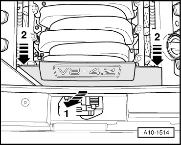
– Remove the front engine cover- arrows -1- and -2-.
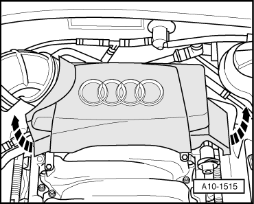
– Remove the rear engine cover -arrows-.
– Disconnect the relevant Camshaft Position (CMP) Sensor electrical harness connector.
Cylinder bank 1 (right):
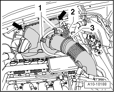
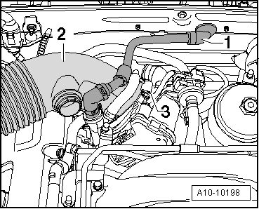
– Remove the fuel hose -1-.
– Disconnect the electrical connector -2- from the Mass Air Flow (MAF) Sensor -G70-.
– Remove the Mass Air Flow (MAF) Sensor -G70- from the air duct hose -3-.
– Remove the upper part of the air filter housing with the Mass Air Flow (MAF) Sensor -G70--arrows-.
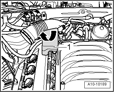
– Remove the resonator -1- in direction of the-arrow- from the air duct hose.
– Disconnect the brake booster vacuum hose -1- at the bulkhead.
– Loosen the clamp -3- and remove the air duct hose -2-.
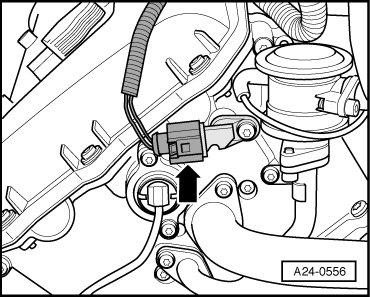
– Disconnect the electrical harness connector -arrow- from the Camshaft Position (CMP) Sensor -G40- at rear of the right cylinder head.
Cylinder bank 2 (left):
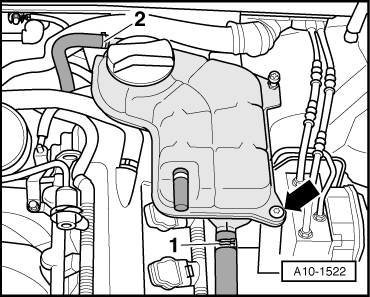
– Remove the screw -arrow- retaining the coolant reservoir.
– Disconnect the electrical connector from Engine Coolant Level (ECL) Warning Switch -F66- at the bottom of the coolant reservoir and set aside the coolant reservoir with the coolant hoses -1- and -2- connected.
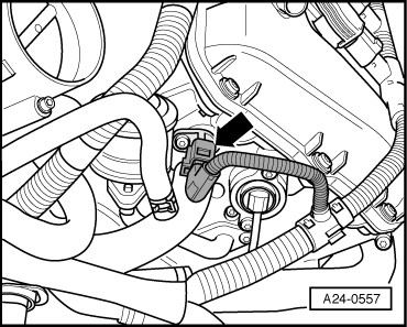
– Disconnect the electrical harness connector -arrow- from the Camshaft Position (CMP) Sensor 2 -G163- at rear of the left cylinder head.
Checking activation
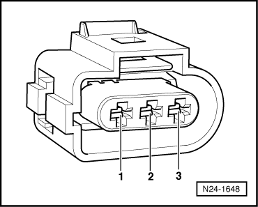
– Using the Voltage Tester -VAG1527B- or equivalent, and a probe from the Connector Test Set -VAG1594C-. Connect the Camshaft position (CMP) sensor electrical harness connector terminals 1 and 2 together and check for voltage leaving the Camshaft position (CMP) sensor electrical harness connector connected to the Camshaft position (CMP) sensor.
– Operate the starter for a few seconds.
The LED must blink.
NoteVoltage testers do not go out completely during low current pick-up between activations by the ECM, but rather continue to glow a little and then get significantly brighter during activation.
– Switch ignition off.
If the LED blinks:
– Replace the faulty Camshaft Position (CMP) Sensor.
If the LED does not blink:
Checking voltage supply
– Using the Multimeter -V.A.G 1526 A- or equivalent, check the following wiring connection for voltage:
Harness connector
Terminal Measure to
1 Engine Ground (GND)
– Switch the ignition on.
Specified value: about 5 V.
– Switch the ignition off.
Checking signal wire
– Using the Multimeter -V.A.G 1526 A- or equivalent, check the following wiring connection for voltage:
Harness connector
Terminal Measure to
2 Engine Ground (GND)
– Switch the ignition on.
Specified value: approx. battery voltage.
– Switch the ignition off.
Checking Ground (GND)
– Using the Multimeter -V.A.G 1526 A- or equivalent, check the following wiring connection for voltage:
Harness connector
Terminal Measure to
3 Battery positive (+)
Specified value: about 10 V.
If the specification is not obtained:
– Check the wiring for a short circuit to Battery positive (+) or an open circuit.
– If necessary, repair the wiring connection.
If no malfunction can be found:
Checking wire connections between Camshaft Position (CMP) sensor and Engine Control Module (ECM)
– Connect the Adapter Cable (121-Point) -VAG1598/31- to the wiring harness of the Engine Control Module (ECM) -J623- ; the ECM is not connected. → Chapter.
– Using the Adapter Cable (121-Point) -VAG1598/31- and Multimeter -V.A.G 1526 A- or equivalent, check the following wiring connections for an open circuit.
l Camshaft Position (CMP) Sensor -G40- (bank 1).
Harness connector
Terminal Test box
Socket
1 Battery positive (+) 98
2 (signal) 87
3 Ground (GND) 108
l Camshaft Position (CMP) Sensor 2 -G163- (bank 2).
Harness connector
Terminal Test box
Socket
1 Battery positive (+) 98
2 (signal) 86
3 Ground (GND) 108
Specified value: Wire resistance max 1.5 Ω.
If the specification is not obtained:
– Check the wiring for a short circuit to Battery positive (+) or an open circuit.
– If necessary, repair the wiring connection.
If no malfunction can be found:
– Replace the Engine Control Module (ECM) -J623-. → Chapter.
Assembly is performed in the reverse order of removal, note the following:
Final procedures
After repair work, the following work steps must be performed in the mentioned sequence:
1 - Check the DTC memory. → Chapter.
2 - If necessary, erase the DTC memory. → Chapter.
3 - If the DTC memory was erased, generate readiness code. → Chapter.
– End diagnosis and switch ignition off.
Thread
Thread Starter
Forum
Replies
Last Post
Charly1215
A6 / S6 (C6 Platform) Discussion
0
11-22-2017 08:49 AM
gateway
A6 / S6 (C6 Platform) Discussion
0
12-02-2012 11:09 AM


