Looking for DIY on spring install
 11-20-2012, 09:33 AM
#1
AudiWorld Newcomer
Thread Starter

Join Date: Jul 2012
Posts: 1
Likes: 0
Received 0 Likes
on
0 Posts
I have come to a speed bump as far as installing my rear springs on my 05 audi A6. Do I need to rent a special type of spring compressor for the rear springs cause they seem to be a pain in the *** to remove.. please help
 11-20-2012, 06:00 PM
#2
AudiWorld Senior Member
Join Date: Jun 2009
Location: Atlantic City Metro Area
Posts: 792
Likes: 0
Received 2 Likes
on
2 Posts
i would love a write up myself but havent seen one yet
seen some non Audi ones on YouTube and they are only somewhat helpful
im no mechanic and have not replaced them myself but im pretty sure spring compressors are needed and i assume they are needed in almost all applications not just A6
are they avail for rent anywhere?
maybe u can borrow from someone near your location?
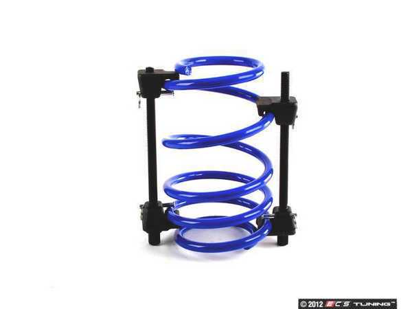
there are some spring compressors on ebay... look for a design that looks solid and secure... i read on some forum that some guy had a big scare when one almost slipped off the springs...trust me u do not want that to happen.
i believe the ones with 2 pieces that clip on the outside of the spring are preferred (not the one piece that go inside the spring)
i like this one.. .. CLICK on Pic
seen some non Audi ones on YouTube and they are only somewhat helpful
im no mechanic and have not replaced them myself but im pretty sure spring compressors are needed and i assume they are needed in almost all applications not just A6
are they avail for rent anywhere?
maybe u can borrow from someone near your location?
there are some spring compressors on ebay... look for a design that looks solid and secure... i read on some forum that some guy had a big scare when one almost slipped off the springs...trust me u do not want that to happen.
i believe the ones with 2 pieces that clip on the outside of the spring are preferred (not the one piece that go inside the spring)
i like this one.. .. CLICK on Pic
Last edited by MainlandMig; 11-20-2012 at 06:23 PM.
11-21-2012, 11:40 AM
#3
AudiWorld Senior Member
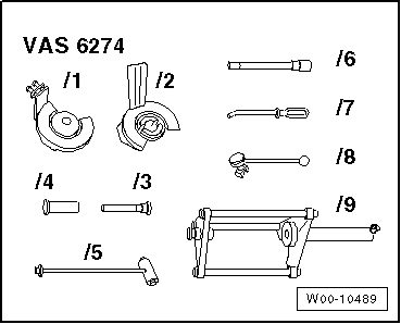
<TABLE cellSpacing=0 cellPadding=0 width="100%"><TBODY><TR><TD class=spalte-text><TABLE class="cc abstand-kap einzug-standard"><TBODY><TR><TD class=titel-kap>Removing and installing coil spring</TD></TR></TBODY></TABLE>[IMG]file:///c:/accessories/html/images/hinweis.gif[/IMG] Note
<TABLE class="cc abstand-liste-erster einzug-standard hinweis-rumpf"><TBODY><TR><TD>The video supplied with the spring compressing system -VAS 6274- can be used as an aid when removing and installing the coil springs.</TD></TR></TBODY></TABLE><TABLE class="cc abstand-standard einzug-standard"><TBODY><TR><TD class=wz-liste-kopf>Special tools and workshop equipment required</TD></TR></TBODY></TABLE>
</TD><TD class=spalte-pfeil></TD><TD class=spalte-marg></TD></TR></TBODY></TABLE><TABLE cellSpacing=0 cellPadding=0 width="100%"><TBODY><TR><TD class=spalte-text><TABLE class="cc abstand-standard einzug-standard "><TBODY><TR><TD class=einzug-liste>t </TD><TD>Spring compressing system -VAS 6274-</TD></TR></TBODY></TABLE>
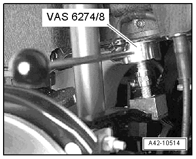
<TABLE cellSpacing=0 cellPadding=0 width="100%"><TBODY><TR><TD class=spalte-text><TABLE class="cc einzug-standard abstand-standard absatz-hervor"><TBODY><TR><TD>Removing</TD></TR></TBODY></TABLE><TABLE class="cc einzug-standard abstand-standard "><TBODY><TR><TD class=einzug-liste>� </TD><TD>Remove rear wheel → Wheels and tyres; Rep. gr.44.</TD></TR></TBODY></TABLE><TABLE class="cc achtung-rahmen abstand-standard einzug-standard"><TBODY><TR><TD class=achtung-inhalt>[IMG]file:///c:/accessories/html/images/Vorsicht.jpg[/IMG] Caution
<TABLE class="cc einzug-standard abstand-liste-erster achtung-rumpf"><TBODY><TR><TD>To avoid damaging the brake line, the flat section of the thrust piece on the spreader device (top) must face towards the front of the vehicle.</TD></TR></TBODY></TABLE>
</TD></TR></TBODY></TABLE><TABLE class="cc einzug-standard abstand-standard "><TBODY><TR><TD class=einzug-liste>� </TD><TD>Insert spreader device -VAS 6274/8- between body and upper transverse link, as shown in illustration, and apply light pressure.
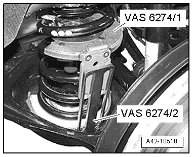
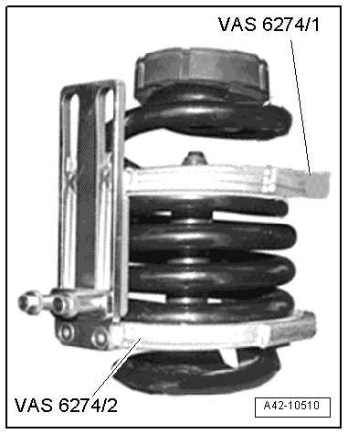
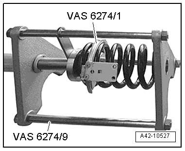
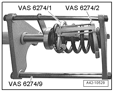
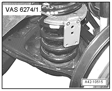
<TABLE cellSpacing=0 cellPadding=0 width="100%"><TBODY><TR><TD class=spalte-text><TABLE class="cc einzug-standard abstand-standard "><TBODY><TR><TD class=einzug-liste>� </TD><TD>Insert thrust plate with locking mechanism -VAS 6274/1- between 2nd and 3rd coils of spring from outside, as shown in illustration.

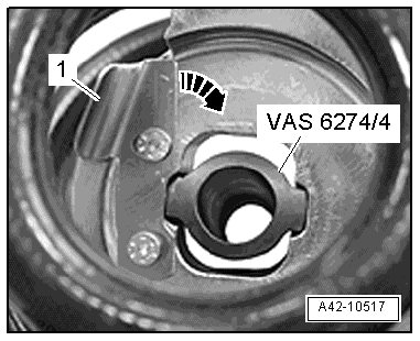
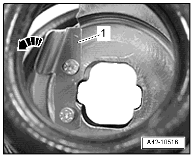
Turn locking lever -1- of thrust plate with locking mechanism -VAS 6274/1- in direction of -arrow-.

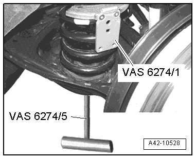
Insert plunger -VAS 6274/4- with T-bar -VAS 6274/5- through hole in bottom link and into thrust plate with locking mechanism -VAS 6274/1-.
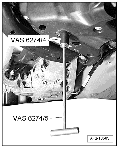
<TABLE class="cc einzug-standard abstand-standard "><TBODY><TR><TD class=einzug-liste>� </TD><TD>Secure plunger -VAS 6274/4- by turning locking lever -1- in direction of -arrow-.</TD></TR></TBODY></TABLE><TABLE class="cc einzug-standard abstand-standard "><TBODY><TR><TD class=einzug-liste>� </TD><TD>Unscrew and remove T-bar -VAS 6274/5-.</TD></TR></TBODY></TABLE>
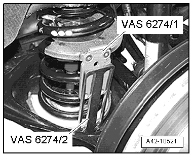
<TABLE cellSpacing=0 cellPadding=0 width="100%"><TBODY><TR><TD class=spalte-text><TABLE class="cc einzug-standard abstand-standard "><TBODY><TR><TD class=einzug-liste>� </TD><TD>Rotate thrust plate with locking mechanism -VAS 6274/1- upwards until it is still just free inside spring.</TD></TR></TBODY></TABLE><TABLE class="cc einzug-standard abstand-standard "><TBODY><TR><TD class=einzug-liste>� </TD><TD>Insert thrust plate with swivel mounting -VAS 6274/2- into spring as shown in illustration, and rotate downwards until it is still just free inside spring.</TD></TR></TBODY></TABLE>[IMG]file:///c:/accessories/html/images/hinweis.gif[/IMG] Note
<TABLE class="cc abstand-liste-erster einzug-standard hinweis-rumpf"><TBODY><TR><TD>If it is not possible to rotate the thrust plate downwards in the spring, unbolt the locating bracket, rotate the thrust plate into the required position and then reattach the locating bracket.
<TABLE cellSpacing=0 cellPadding=0 width="100%"><TBODY><TR><TD class=spalte-text><TABLE class="cc einzug-standard abstand-standard "><TBODY><TR><TD></TD></TR></TBODY></TABLE><TABLE class="cc achtung-rahmen abstand-standard einzug-standard"><TBODY><TR><TD class=achtung-inhalt>[IMG]file:///c:/accessories/html/images/Vorsicht.jpg[/IMG] Caution
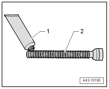
<TABLE class="cc abstand-liste-erster einzug-standard achtung-rumpf"><TBODY><TR><TD class=einzug-liste>t </TD><TD>Before removing and installing any of the springs, always lubricate the front of the spindle lightly with the grease supplied.</TD></TR></TBODY></TABLE><TABLE class="cc abstand-liste einzug-standard achtung-rumpf"><TBODY><TR><TD class=einzug-liste>t </TD><TD>Lubricate the spindle only with the grease supplied. If other greases are used the spindle will be damaged.</TD></TR></TBODY></TABLE>
</TD></TR></TBODY></TABLE><TABLE class="cc einzug-standard abstand-standard "><TBODY><TR><TD class=einzug-liste>� </TD><TD>Lubricate the front of the spindle -VAS 6274/3- lightly with the grease supplied.</TD></TR></TBODY></TABLE><TABLE class="cc abstand-standard erlaeutrg-leg"><TBODY><TR><TD class=einzug-nummer>1 - </TD><TD>Lubricating grease from spring compressing system -VAS 6274-</TD></TR></TBODY></TABLE><TABLE class="cc abstand-liste erlaeutrg-leg"><TBODY><TR><TD class=einzug-nummer>2 - </TD><TD>Spindle -VAS 6274/3-</TD></TR></TBODY></TABLE>
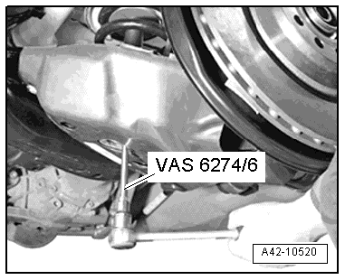
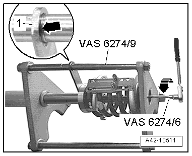
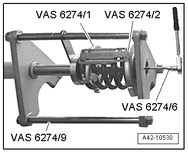
<TABLE cellSpacing=0 cellPadding=0 width="100%"><TBODY><TR><TD class=spalte-text><TABLE class="cc einzug-standard abstand-standard "><TBODY><TR><TD class=einzug-liste>� </TD><TD>Insert socket -VAS 6274/6- in spindle -VAS 6274/3- and screw upwards through hole in bottom link.</TD></TR></TBODY></TABLE><TABLE class="cc abstand-standard einzug-standard "><TBODY><TR><TD class=einzug-liste>l </TD><TD>The spindle should screw easily into the thread of the plunger. Do not use force.</TD></TR></TBODY></TABLE><TABLE class="cc abstand-liste einzug-standard "><TBODY><TR><TD class=einzug-liste>l </TD><TD>The collar of the spindle must be seated correctly in the axial bearing of the thrust plate with swivel mounting -VAS 6274/2-.
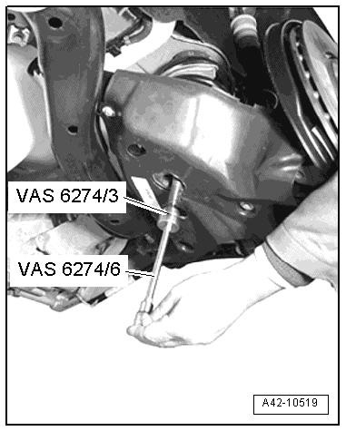
<TABLE cellSpacing=0 cellPadding=0 width="100%"><TBODY><TR><TD class=spalte-text><TABLE class="cc einzug-standard abstand-standard "><TBODY><TR><TD class=einzug-liste>� </TD><TD>Hand-tighten spindle -VAS 6274/3- using socket -VAS 6274/6-.</TD></TR></TBODY></TABLE>[IMG]file:///c:/accessories/html/images/hinweis.gif[/IMG] Note
<TABLE class="cc abstand-liste-erster einzug-standard hinweis-rumpf"><TBODY><TR><TD class=einzug-liste>t </TD><TD>In order to be able to compress the different types of spring as far as possible, the two thrust plates should be positioned so there are 4<SUP class=hochtief>1</SUP>/<SUB class=hochtief>4</SUB> to 4<SUP class=hochtief>3</SUP>/<SUB class=hochtief>4</SUB> spring coils between them.</TD></TR></TBODY></TABLE>
<TABLE cellSpacing=0 cellPadding=0 width="100%"><TBODY><TR><TD class=spalte-text><TABLE class="cc abstand-liste einzug-standard hinweis-rumpf"><TBODY><TR><TD class=einzug-liste>t </TD><TD>If necessary, move round the upper locating bracket 180� and rotate -VAS 6274/1- 180� further (from 4<SUP class=hochtief>1</SUP>/<SUB class=hochtief>4</SUB> to 4<SUP class=hochtief>3</SUP>/<SUB class=hochtief>4</SUB> spring coils).</TD></TR></TBODY></TABLE><TABLE class="cc abstand-standard einzug-standard "><TBODY><TR><TD class=einzug-liste>l </TD><TD>The locating bracket should be facing slightly forwards in the vicinity of the brake splash plate, as shown in the illustration.</TD></TR></TBODY></TABLE>

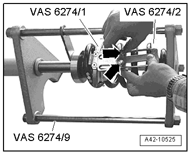
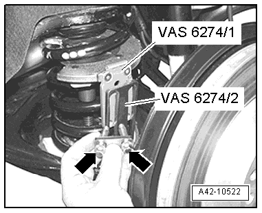
<TABLE cellSpacing=0 cellPadding=0 width="100%"><TBODY><TR><TD class=spalte-text><TABLE class="cc einzug-standard abstand-standard "><TBODY><TR><TD class=einzug-liste>� </TD><TD>Align thrust plate with locking mechanism -VAS 6274/1- and thrust plate with swivel mounting -VAS 6274/2- with each other so that the two locating brackets can be bolted together.</TD></TR></TBODY></TABLE><TABLE class="cc einzug-standard abstand-standard "><TBODY><TR><TD class=einzug-liste>� </TD><TD>Screw in flange bolts -arrows- hand-tight.</TD></TR></TBODY></TABLE><TABLE class="cc achtung-rahmen abstand-standard einzug-standard"><TBODY><TR><TD class=achtung-inhalt>[IMG]file:///c:/accessories/html/images/achtung.jpg[/IMG] WARNING
<TABLE class="cc einzug-standard abstand-liste-erster achtung-rumpf"><TBODY><TR><TD>The coil spring must be compressed or released only when the two locating brackets are joined together by the flange bolts -arrows-.</TD></TR></TBODY></TABLE>

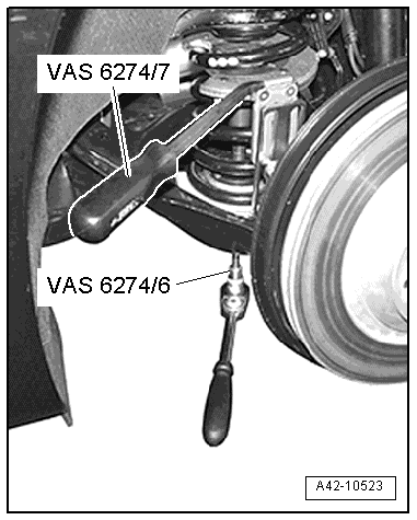
<TABLE cellSpacing=0 cellPadding=0 width="100%"><TBODY><TR><TD class=spalte-text><TABLE class="cc einzug-standard abstand-standard "><TBODY><TR><TD class=einzug-liste>� </TD><TD>Now compress coil spring by turning socket -VAS 6274/6- while holding spring compressor with counterhold tool -VAS 6274/7-.</TD></TR></TBODY></TABLE><TABLE class="cc abstand-standard einzug-standard "><TBODY><TR><TD class=einzug-liste>l </TD><TD>Stop compressing the spring when the plunger -VAS 6274/4- makes contact with the bearing of the thrust plate with swivel mounting -VAS 6274/2-, or the flange bolts of the locating brackets reach the end stop.</TD></TR></TBODY></TABLE><TABLE class="cc achtung-rahmen abstand-standard einzug-standard"><TBODY><TR><TD class=achtung-inhalt>[IMG]file:///c:/accessories/html/images/Vorsicht.jpg[/IMG] Caution
<TABLE class="cc abstand-liste-erster einzug-standard achtung-rumpf"><TBODY><TR><TD class=einzug-liste>l </TD><TD>When compressing the spring, make sure the flange bolts do not make contact with the stop on the thrust plate.</TD></TR></TBODY></TABLE><TABLE class="cc abstand-liste einzug-standard achtung-rumpf"><TBODY><TR><TD class=einzug-liste>l </TD><TD>The locating bracket of the thrust plate must not make contact with the stop on the thrust plate.</TD></TR></TBODY></TABLE>
<TABLE cellSpacing=0 cellPadding=0 width="100%"><TBODY><TR><TD class=spalte-text><TABLE class="cc einzug-standard abstand-standard "><TBODY><TR><TD class=einzug-liste>� </TD><TD>Carefully take out compressed coil spring.</TD></TR></TBODY></TABLE><TABLE class="cc achtung-rahmen abstand-standard einzug-standard"><TBODY><TR><TD class=achtung-inhalt>[IMG]file:///c:/accessories/html/images/achtung.jpg[/IMG] WARNING
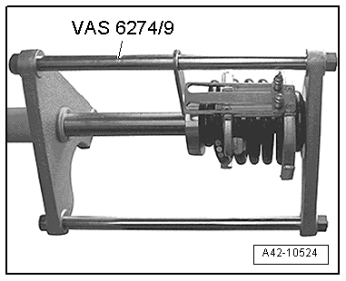
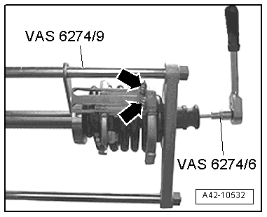
<TABLE class="cc abstand-liste-erster einzug-standard achtung-rumpf"><TBODY><TR><TD class=einzug-liste>t </TD><TD>The coil spring may only be compressed or released when it is in the vehicle or in the hydraulic tensioning device -VAS 6274/9-.</TD></TR></TBODY></TABLE><TABLE class="cc abstand-liste einzug-standard achtung-rumpf"><TBODY><TR><TD class=einzug-liste>t </TD><TD>The coil spring must on no account be released by turning the spindle -VAS 6274/3- because the spindle is too short. In the compressed condition the spring is under very high pressure.</TD></TR></TBODY></TABLE>
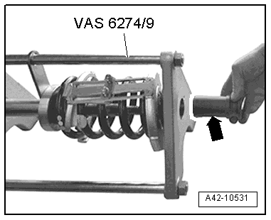
<TABLE cellSpacing=0 cellPadding=0 width="100%"><TBODY><TR><TD class=spalte-text><TABLE class="cc einzug-standard abstand-standard "><TBODY><TR><TD class=einzug-liste>� </TD><TD>Insert compressed coil spring in correct position in hydraulic tensioning device -VAS 6274/9- and compress spring slightly further by operating hydraulic pump.</TD></TR></TBODY></TABLE><TABLE class="cc abstand-standard einzug-standard "><TBODY><TR><TD class=einzug-liste>l </TD><TD>The free end of the spring coil must lie against the stop of the take-up plate.</TD></TR></TBODY></TABLE>
</TD></TR></TBODY></TABLE>
</TD></TR></TBODY></TABLE><TABLE cellSpacing=0 cellPadding=0 width="100%"><TBODY><TR><TD class=spalte-text><TABLE class="cc einzug-standard abstand-standard "><TBODY><TR><TD class=einzug-liste>� </TD><TD>Unscrew spindle -VAS 6274/3- from plunger -VAS 6274/4- using socket -VAS 6274/6- and remove from spring.</TD></TR></TBODY></TABLE><TABLE class="cc achtung-rahmen abstand-standard einzug-standard"><TBODY><TR><TD class=achtung-inhalt>[IMG]file:///c:/accessories/html/images/achtung.jpg[/IMG] WARNING
<TABLE class="cc einzug-standard abstand-liste-erster achtung-rumpf"><TBODY><TR><TD>Risk of accident! The coil spring is now only held by the hydraulic tensioning device -VAS 6274/9-.</TD></TR></TBODY></TABLE>
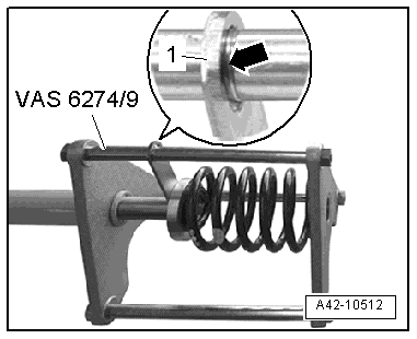
</TD></TR></TBODY></TABLE><TABLE class="cc einzug-standard abstand-standard "><TBODY><TR><TD class=einzug-liste>� </TD><TD>Slacken tensioning device via foot pump -VAS 6179- until guide -1- is level with marking -arrow-.</TD></TR></TBODY></TABLE>
<TABLE cellSpacing=0 cellPadding=0 width="100%"><TBODY><TR><TD class=spalte-text><TABLE class="cc einzug-standard abstand-standard "><TBODY><TR><TD class=einzug-liste>� </TD><TD>Remove both flange bolts -arrows-.</TD></TR></TBODY></TABLE><TABLE class="cc achtung-rahmen abstand-standard einzug-standard"><TBODY><TR><TD class=achtung-inhalt>[IMG]file:///c:/accessories/html/images/achtung.jpg[/IMG] WARNING
<TABLE class="cc einzug-standard abstand-liste-erster achtung-rumpf"><TBODY><TR><TD>The flange bolts must not be unscrewed until the spring has been completely slackened.</TD></TR></TBODY></TABLE>
</TD></TR></TBODY></TABLE><TABLE class="cc einzug-standard abstand-standard "><TBODY><TR><TD class=einzug-liste>� </TD><TD>Remove thrust plate with swivel mounting -VAS 6274/2- from coil spring.</TD></TR></TBODY></TABLE>

<TABLE cellSpacing=0 cellPadding=0 width="100%"><TBODY><TR><TD class=spalte-text><TABLE class="cc einzug-standard abstand-standard "><TBODY><TR><TD class=einzug-liste>� </TD><TD>Screw T-bar -VAS 6274/5- into plunger -VAS 6274/4-.</TD></TR></TBODY></TABLE>
 </TD></TR></TBODY></TABLE>
<TABLE cellSpacing=0 cellPadding=0 width="100%"><TBODY><TR><TD class=spalte-text><TABLE class="cc einzug-standard abstand-standard "><TBODY><TR><TD class=einzug-liste>� </TD><TD>Turn locking lever -1- of thrust plate with locking mechanism -VAS 6274/1- in direction of -arrow-.</TD></TR></TBODY></TABLE><TABLE class="cc einzug-standard abstand-standard "><TBODY><TR><TD class=einzug-liste>� </TD><TD>Take plunger -VAS 6274/4- out of locking mechanism.</TD></TR></TBODY></TABLE><TABLE class="cc einzug-standard abstand-standard "><TBODY><TR><TD class=einzug-liste>� </TD><TD>Remove thrust plate with locking mechanism -VAS 6274/1- from coil spring.</TD></TR></TBODY></TABLE><TABLE class="cc einzug-standard abstand-standard "><TBODY><TR><TD class=einzug-liste>� </TD><TD>Release spring compressor via foot pump and take coil spring out of hydraulic tensioning device -VAS 6274/9-.</TD></TR></TBODY></TABLE>

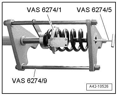
<TABLE cellSpacing=0 cellPadding=0 width="100%"><TBODY><TR><TD class=spalte-text><TABLE class="cc einzug-standard abstand-standard absatz-hervor"><TBODY><TR><TD>Installing</TD></TR></TBODY></TABLE><TABLE class="cc einzug-standard abstand-standard "><TBODY><TR><TD class=einzug-liste>� </TD><TD>Insert coil spring in correct position in hydraulic tensioning device -VAS 6274/9- and compress spring slightly on push rod by operating hydraulic pump.</TD></TR></TBODY></TABLE><TABLE class="cc abstand-standard einzug-standard "><TBODY><TR><TD class=einzug-liste>l </TD><TD>Guide -1- must be level with marking -arrow-.</TD></TR></TBODY></TABLE>
<TABLE cellSpacing=0 cellPadding=0 width="100%"><TBODY><TR><TD class=spalte-text><TABLE class="cc einzug-standard abstand-standard "><TBODY><TR><TD class=einzug-liste>� </TD><TD>Insert thrust plate with locking mechanism -VAS 6274/1- into coil spring.</TD></TR></TBODY></TABLE>
<TABLE cellSpacing=0 cellPadding=0 width="100%"><TBODY><TR><TD class=spalte-text><TABLE class="cc einzug-standard abstand-standard "><TBODY><TR><TD class=einzug-liste>� </TD><TD>Insert plunger -VAS 6274/4- with T-bar -VAS 6274/5- into thrust plate with locking mechanism -VAS 6274/1-.</TD></TR></TBODY></TABLE>

<TABLE cellSpacing=0 cellPadding=0 width="100%"><TBODY><TR><TD class=spalte-text><TABLE class="cc einzug-standard abstand-standard "><TBODY><TR><TD class=einzug-liste>� </TD><TD>Secure plunger -VAS 6274/4- with locking lever -1--arrow-.</TD></TR></TBODY></TABLE><TABLE class="cc einzug-standard abstand-standard "><TBODY><TR><TD class=einzug-liste>� </TD><TD>Unscrew and remove T-bar -VAS 6274/5-.</TD></TR></TBODY></TABLE>

<TABLE cellSpacing=0 cellPadding=0 width="100%"><TBODY><TR><TD class=spalte-text><TABLE class="cc einzug-standard abstand-standard "><TBODY><TR><TD class=einzug-liste>� </TD><TD>Insert thrust plate with swivel mounting -VAS 6274/2- into coil spring as shown in illustration.</TD></TR></TBODY></TABLE>
<TABLE cellSpacing=0 cellPadding=0 width="100%"><TBODY><TR><TD class=spalte-text><TABLE class="cc einzug-standard abstand-standard "><TBODY><TR><TD class=einzug-liste>� </TD><TD>Fit spindle -VAS 6274/3- onto socket -VAS 6274/6- and screw spindle into thread of plunger -VAS 6274/4-.</TD></TR></TBODY></TABLE><TABLE class="cc einzug-standard abstand-standard "><TBODY><TR><TD class=einzug-liste>� </TD><TD>Without using force, rotate thrust plate with locking mechanism -VAS 6274/1- and thrust plate with swivel mounting -VAS 6274/2- to a position where they can compress the spring to the maximum extent.</TD></TR></TBODY></TABLE>[IMG]file:///c:/accessories/html/images/hinweis.gif[/IMG] Note
<TABLE class="cc abstand-liste-erster einzug-standard hinweis-rumpf"><TBODY><TR><TD class=einzug-liste>t </TD><TD>In order to be able to compress the different types of spring as far as possible, the two thrust plates should be positioned so there are 4<SUP class=hochtief>1</SUP>/<SUB class=hochtief>4</SUB> to 4<SUP class=hochtief>3</SUP>/<SUB class=hochtief>4</SUB> spring coils between them.</TD></TR></TBODY></TABLE><TABLE class="cc abstand-liste einzug-standard hinweis-rumpf"><TBODY><TR><TD class=einzug-liste>t </TD><TD>If necessary, move round the upper locating bracket 180� and rotate -VAS 6274/1- 180� further (from 4<SUP class=hochtief>1</SUP>/<SUB class=hochtief>4</SUB> to 4<SUP class=hochtief>3</SUP>/<SUB class=hochtief>4</SUB> spring coils).</TD></TR></TBODY></TABLE><TABLE class="cc einzug-standard abstand-standard "><TBODY><TR><TD class=einzug-liste>� </TD><TD>Take out socket.</TD></TR></TBODY></TABLE>
<TABLE cellSpacing=0 cellPadding=0 width="100%"><TBODY><TR><TD class=spalte-text><TABLE class="cc einzug-standard abstand-standard "><TBODY><TR><TD class=einzug-liste>� </TD><TD>Align thrust plate with locking mechanism -VAS 6274/1- and thrust plate with swivel mounting -VAS 6274/2- with each other so that the two locating brackets can be bolted together.</TD></TR></TBODY></TABLE><TABLE class="cc einzug-standard abstand-standard "><TBODY><TR><TD class=einzug-liste>� </TD><TD>Screw in flange bolts -arrows- hand-tight.</TD></TR></TBODY></TABLE><TABLE class="cc abstand-standard einzug-standard "><TBODY><TR><TD class=einzug-liste>l </TD><TD>The locating bracket should be close to the push rod at the top, as shown in the illustration.</TD></TR></TBODY></TABLE><TABLE class="cc achtung-rahmen abstand-standard einzug-standard"><TBODY><TR><TD class=achtung-inhalt>[IMG]file:///c:/accessories/html/images/achtung.jpg[/IMG] WARNING
<TABLE class="cc einzug-standard abstand-liste-erster achtung-rumpf"><TBODY><TR><TD>The coil spring must be compressed or released only when the two locating brackets are joined together by the flange bolts -arrows-.</TD></TR></TBODY></TABLE>
</TD></TR></TBODY></TABLE>Align thrust plate with locking mechanism. - vas 6274/1 - & thrust plate with swivel mounting - vas 6274/2 - with each other so that the two locating brakets can be bolted together</TD></TR></TBODY></TABLE>
<TABLE class="cc einzug-standard abstand-standard "><TBODY><TR><TD class=einzug-liste>� </TD><TD>Screw in flange bolts -arrows- hand-tight.</TD></TR></TBODY></TABLE>
<TABLE class="cc abstand-standard einzug-standard "><TBODY><TR><TD class=einzug-liste>l </TD><TD>The locating bracket should be close to the push rod at the top, as shown in the illustration.</TD></TR></TBODY></TABLE><TABLE class="cc achtung-rahmen abstand-standard einzug-standard"><TBODY><TR><TD class=achtung-inhalt>[IMG]file:///c:/accessories/html/images/achtung.jpg[/IMG] WARNING
<TABLE class="cc einzug-standard abstand-liste-erster achtung-rumpf"><TBODY><TR><TD>The coil spring must be compressed or released only when the two locating brackets are joined together by the flange bolts -arrows-.</TD></TR></TBODY></TABLE>The coil spring must be compressed or released only when the two locating brackets are joined together by the flange bolts -arrows-.
</TD></TR></TBODY></TABLE>
<TABLE cellSpacing=0 cellPadding=0 width="100%"><TBODY><TR><TD class=spalte-text><TABLE class="cc einzug-standard abstand-standard "><TBODY><TR><TD class=einzug-liste>� </TD><TD>Insert guide bush -arrow- for centring spindle -VAS 6274/3- in hydraulic tensioning device -VAS 6274/9-.</TD></TR></TBODY></TABLE><TABLE class="cc abstand-standard einzug-standard "><TBODY><TR><TD class=einzug-liste>l </TD><TD>The collar of the spindle should be located in the guide bush after the spring has been compressed.</TD></TR></TBODY></TABLE></TD></TR></TBODY></TABLE>
</TD></TR></TBODY></TABLE>
<TABLE cellSpacing=0 cellPadding=0 width="100%"><TBODY><TR><TD class=spalte-text><TABLE class="cc einzug-standard abstand-standard "><TBODY><TR><TD class=einzug-liste>� </TD><TD>Insert guide bush -arrow- for centring spindle -VAS 6274/3- in hydraulic tensioning device -VAS 6274/9-.</TD></TR></TBODY></TABLE><TABLE class="cc abstand-standard einzug-standard "><TBODY><TR><TD class=einzug-liste>l </TD><TD>The collar of the spindle should be located in the guide bush after the spring has been compressed.</TD></TR></TBODY></TABLE>
 </TD></TR></TBODY></TABLE>
</TD></TR></TBODY></TABLE>
</TD></TR></TBODY></TABLE>
</TD></TR></TBODY></TABLE>
<TABLE cellSpacing=0 cellPadding=0 width="100%"><TBODY><TR><TD class=spalte-text><TABLE class="cc einzug-standard abstand-standard "><TBODY><TR><TD class=einzug-liste>� </TD><TD>Slowly compress coil spring by operating hydraulic pump and at the same time take up travel on spindle -VAS 6274/3- by turning spindle with socket -VAS 6274/6-.</TD></TR></TBODY></TABLE><TABLE class="cc abstand-standard einzug-standard "><TBODY><TR><TD class=einzug-liste>l </TD><TD>Stop compressing the spring when the plunger -VAS 6274/4- makes contact with the bearing of the thrust plate with swivel mounting -VAS 6274/2-, or the flange bolts -arrows- of the locating brackets reach the end stop.</TD></TR></TBODY></TABLE>
 </TD></TR></TBODY></TABLE>
</TD></TR></TBODY></TABLE>
</TD></TR></TBODY></TABLE>
</TD></TR></TBODY></TABLE>
<TABLE cellSpacing=0 cellPadding=0 width="100%"><TBODY><TR><TD class=spalte-text><TABLE class="cc einzug-standard abstand-standard "><TBODY><TR><TD class=einzug-liste>� </TD><TD>Slowly open valve on hydraulic pump and take compressed coil spring out of hydraulic tensioning device -VAS 6274/9-.</TD></TR></TBODY></TABLE><TABLE class="cc einzug-standard abstand-standard "><TBODY><TR><TD class=einzug-liste>� </TD><TD>Locate compressed coil spring in correct position in vehicle.</TD></TR></TBODY></TABLE>[IMG]file:///c:/accessories/html/images/hinweis.gif[/IMG] Note
<TABLE class="cc abstand-liste-erster einzug-standard hinweis-rumpf"><TBODY><TR><TD>Make sure that the spring seats (top and bottom) are positioned correctly.</TD></TR></TBODY></TABLE><TABLE class="cc achtung-rahmen abstand-standard einzug-standard"><TBODY><TR><TD class=achtung-inhalt>[IMG]file:///c:/accessories/html/images/achtung.jpg[/IMG] WARNING
<TABLE class="cc einzug-standard abstand-liste-erster achtung-rumpf"><TBODY><TR><TD>Risk of accident! Do not use compressed-air impact wrenches to compress or release the coil spring.</TD></TR></TBODY></TABLE>

</TD></TR></TBODY></TABLE>
</TD></TR></TBODY></TABLE>
</TD></TR></TBODY></TABLE>
</TD></TR></TBODY></TABLE></TD></TR></TBODY></TABLE>
<TABLE class="cc einzug-standard abstand-standard "><TBODY><TR><TD class=einzug-liste>� </TD><TD>Now release coil spring by turning socket -VAS 6274/6- while holding spring compressor with counterhold tool -VAS 6274/7-.</TD></TR></TBODY></TABLE>

</TD></TR></TBODY></TABLE></TD></TR></TBODY></TABLE>
</TD></TR></TBODY></TABLE></TD></TR></TBODY></TABLE>
<TABLE cellSpacing=0 cellPadding=0 width="100%"><TBODY><TR><TD class=spalte-text><TABLE class="cc einzug-standard abstand-standard "><TBODY><TR><TD class=einzug-liste>� </TD><TD>Unscrew spindle -VAS 6274/3- from plunger -VAS 6274/4- using socket -VAS 6274/6- and remove.</TD></TR></TBODY></TABLE>[IMG]file:///c:/accessories/html/images/hinweis.gif[/IMG] Note
<TABLE class="cc abstand-liste-erster einzug-standard hinweis-rumpf"><TBODY><TR><TD>The spindle is easier to remove if the opening on thrust plate with locking mechanism -VAS 6274/1- is facing outwards.</TD></TR></TBODY></TABLE>

</TD></TR></TBODY></TABLE>
</TD></TR></TBODY></TABLE>
</TD></TR></TBODY></TABLE>
</TD></TR></TBODY></TABLE><TABLE cellSpacing=0 cellPadding=0 width="100%"><TBODY><TR><TD class=spalte-text><TABLE class="cc einzug-standard abstand-standard "><TBODY><TR><TD class=einzug-liste>� </TD><TD>Remove flange bolts -arrows- from locating brackets.</TD></TR></TBODY></TABLE>
 </TD></TR></TBODY></TABLE></TD></TR></TBODY></TABLE>
</TD></TR></TBODY></TABLE>
</TD></TR></TBODY></TABLE>
<TABLE cellSpacing=0 cellPadding=0 width="100%"><TBODY><TR><TD class=spalte-text><TABLE class="cc einzug-standard abstand-standard "><TBODY><TR><TD class=einzug-liste>� </TD><TD>Rotate thrust plate with swivel mounting -VAS 6274/2- upwards slightly and remove from coil spring.</TD></TR></TBODY></TABLE>[IMG]file:///c:/accessories/html/images/hinweis.gif[/IMG] Note
<TABLE class="cc abstand-liste-erster einzug-standard hinweis-rumpf"><TBODY><TR><TD>If it is not possible to remove the thrust plate from the spring, unbolt the locating bracket, take the thrust plate out of the spring and then reattach the locating bracket.</TD></TR></TBODY></TABLE>
</TD></TR></TBODY></TABLE>
</TD></TR></TBODY></TABLE>
</TD></TR></TBODY></TABLE><TABLE class="cc einzug-standard abstand-standard "><TBODY><TR><TD class=einzug-liste>� </TD><TD>Rotate thrust plate with locking mechanism -VAS 6274/1- downwards slightly.</TD></TR></TBODY></TABLE><TABLE class="cc einzug-standard abstand-standard "><TBODY><TR><TD class=einzug-liste>� </TD><TD>Screw T-bar -VAS 6274/5- into plunger -VAS 6274/4-.</TD></TR></TBODY></TABLE>
 </TD></TR></TBODY></TABLE>
</TD></TR></TBODY></TABLE></TD></TR></TBODY></TABLE>
</TD></TR></TBODY></TABLE>
<TABLE cellSpacing=0 cellPadding=0 width="100%"><TBODY><TR><TD class=spalte-text><TABLE class="cc einzug-standard abstand-standard "><TBODY><TR><TD class=einzug-liste>� </TD><TD>Turn locking lever -1- of thrust plate with locking mechanism -VAS 6274/1- in direction of -arrow-.</TD></TR></TBODY></TABLE><TABLE class="cc einzug-standard abstand-standard "><TBODY><TR><TD class=einzug-liste>� </TD><TD>Take plunger -VAS 6274/4- out of locking mechanism and remove through hole in bottom link.</TD></TR></TBODY></TABLE>
<TABLE cellSpacing=0 cellPadding=0 width="100%"><TBODY><TR><TD class=spalte-text><TABLE class="cc einzug-standard abstand-standard "><TBODY><TR><TD class=einzug-liste>� </TD><TD>Remove thrust plate with locking mechanism -VAS 6274/1- from coil spring.</TD></TR></TBODY></TABLE>
 </TD></TR></TBODY></TABLE>
</TD></TR></TBODY></TABLE>
<TABLE cellSpacing=0 cellPadding=0 width="100%"><TBODY><TR><TD class=spalte-text><TABLE class="cc einzug-standard abstand-standard "><TBODY><TR><TD class=einzug-liste>� </TD><TD>Slacken and remove spreader device -VAS 6274/8-.</TD></TR></TBODY></TABLE>
 </TD></TR></TBODY></TABLE>
Last edited by royclark; 11-21-2012 at 12:17 PM.


Thread
Thread Starter
Forum
Replies
Last Post
Murph
A6 / S6 (C5 Platform) Discussion
1
03-07-2009 08:19 AM
Is a spring install a huge deal for your average shop to do? Is there anything i have to worry about
BlackS4tt (Josh)
S4 / RS4 (B5 Platform) Discussion
18
12-08-2004 12:14 PM