Audi A8/S8 Upper Control Arm Bushing Rebuild
 12-30-2017, 06:28 PM
#1
AudiWorld Super User
Thread Starter
Audi A8/S8 Upper Control Arm Bushing Rebuild
Replacing the upper control arm bushings on the D3 Audi A8 and S8 isn't hard, but I would consider it a more advanced repair job, not a simple DIY. The best advice I could give would be to go slow and take your time. There are only a few things you can screw up, but it's best when you get it right without any issues.
I decided to do this after owning my S8 5 years, it had 80K miles on it and I was getting a more pronounced "clunk" in the front suspension, especially on the left hand side when I would have the wheel turned hard right and going up a large incline, like turning into a parking lot with a small ramp going into it. That is now gone.
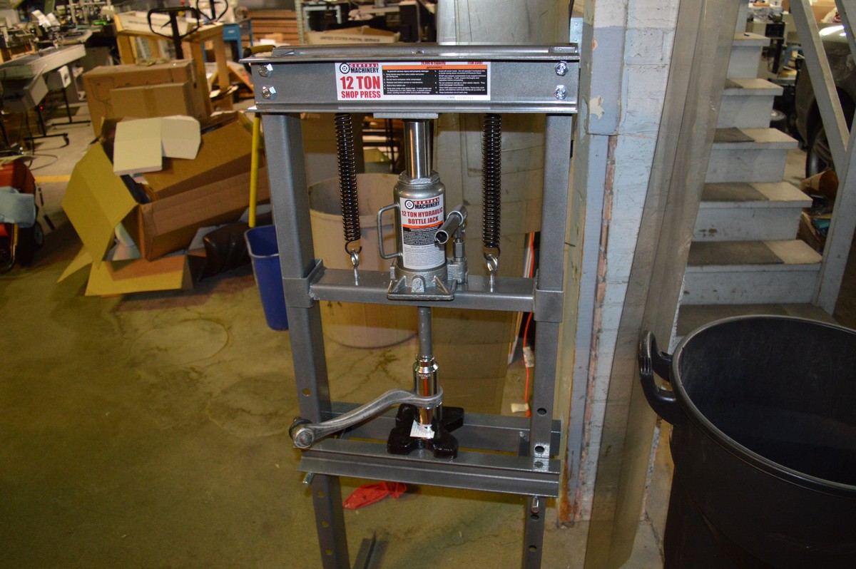
For about $250 including tools, I was able to rebuild all four upper links and replace the sway bar links. Included in this is the $110 I spent at Harbor Freight Tools for the 12 tons press. So pretty darn cheap, and I enjoyed doing the work. I spent about 10-11 hours doing this over two days. The first side was longer, the second side was a walk in the park, about 3 hours.
Here are my notes and some pictures, there are many ways to do this, this is mine and found it to be easy once I figured it out and used this procedure on the second side.
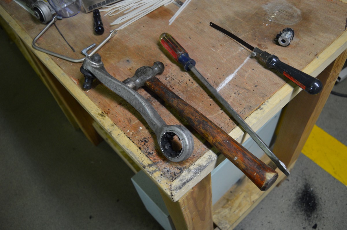
Tools Required
Jack Stands
Jack
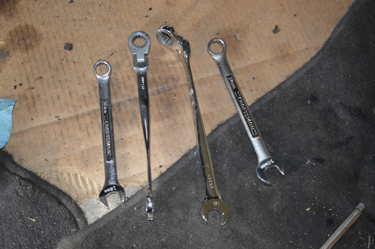
14 mm ratcheting wrench that pivots or ratchet with 14 mm socket
14 mm combination wrench
16 mm ratcheting wrench that pivots
16 mm combination wrench
18 mm ratcheting wrench that pivots
18 mm combination wrench
10 mm open wrench
16mm socket wrench, both a deep well and standard short socket
Large screwdriver to pry the control arm pinch points open
Press if you plan to press the bushings in and out yourself
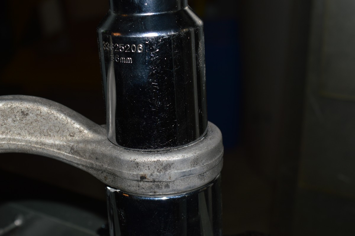
36 mm socket to press the bushing in
1 3/4" or 1 13/16" socket to receive the control arm during the pressing process
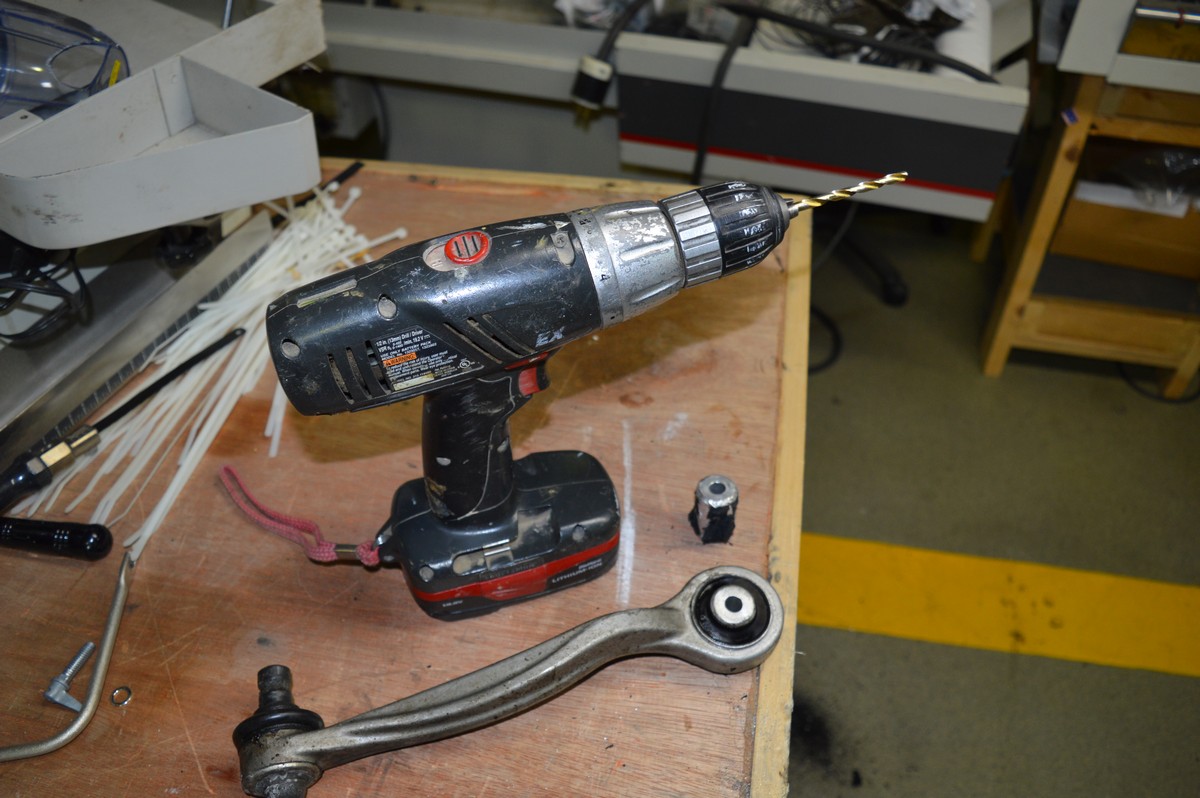
Drill
Drill bit to drill out the rubber, 1/4" or slightly smaller
Hacksaw blade and handle to mount the blade in to cut the bushing
Calipers to measure bushing to get it round
Other standard tools and wrenches
I would not try this job without the ratcheting wrenches that pivot. This is for tightening of the control arms after they are installed. I really don't know how you would do it without them. The control arm is 16 mm, and the air strut assembly to lower control arm is 18 mm, you don't need this one, but it sure is nice. These are from GearWrench 85288 12 Piece X-Beam Metric Flex Combination Ratcheting Wrench Set. A great addition to your tool box!
Parts Needed
Pinch bolt and nut
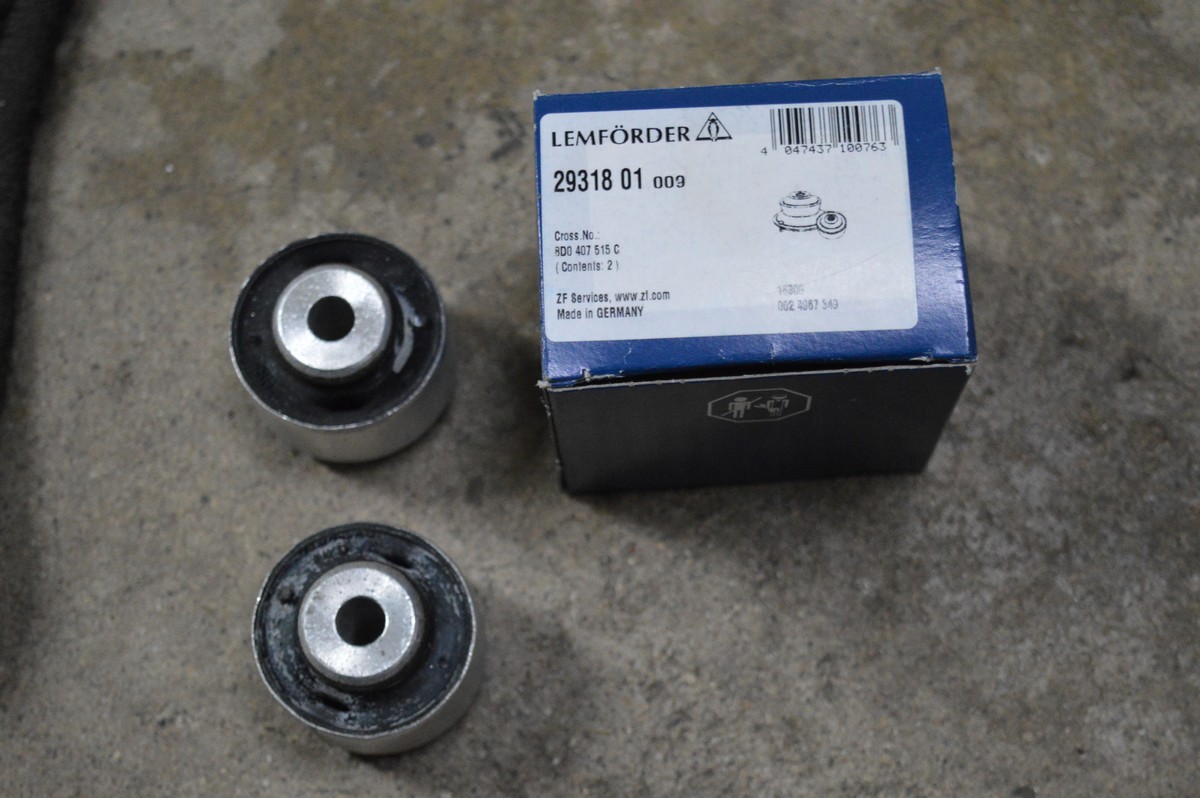
Control Arm Bushings, Lemforder Part Number 29318 01, Audi 8D0 407 515 C, note that these are specifically for the A8, but I used them on my S8.
Sway Bar Links (if replacing them), Lemforder Part Number 30536 01, Audi 4E0 411 317 E
Inner fender plastic push pins if removing the inner fender (this procedure does not have you remove it), quantity 10, 5 per side.
Lemforder bushings, there were two in a package when I ordered them from Rockauto.com, about $10 each.
This thread has so much information on it regarding these parts, please look it over:
https://www.audiworld.com/forums/a8-...ences-2874055/
Procedure
This procedure shows the right hand side, but almost all is the same for the left hand side with exception of getting to the top side air strut assembly mounting bolt, you just have to move the coolant expansion tank for the left hand side, just a bit.
I DID NOT remove the inner fender for the right hand side, but did for the left hand side. I’m sure you could do it on the left hand side without removing it, but since I didn’t do it that way, I’m not 100% sure.
Put the car up on jack stands.
Remove the wheels.
Unbolt the sway bar link from the control arm, I replaced these with new Lemorder units (OEM supplier) that I bought on ebay for about $26 each, great deal!
Remove the upright pinch bolt. Hopefully you won’t have trouble with this. Once you have the nut off and it’s spinning, I used an electric impact driver to turn it, then used a small pry lever to push on the end with the nut to get it moving in the correct direction (out). Once you get it out an inch or two, put a 14mm closed end wrench on the bolt head side, drop it over the head and then pull on it while using the impact driver to get the bolt out. REPLACE BOLT AND NUT.
Now you have to get the control arm out of the upright. Spray the pinch bolt assembly with WD-40, it will help the control arms come out easier.
The short one (aft) was relatively easy to pop out on both sides. For the long one (forward), I put a large screw driver in the pinch area and tapped it with a hammer to open it up slightly (SEE WARNINGS ABOUT DOING THIS IN REPLY 2 & 3 BELOW, it is not recommended, but worked for me), then using a rubber mallet, just hit the control arm upwards and out it popped.
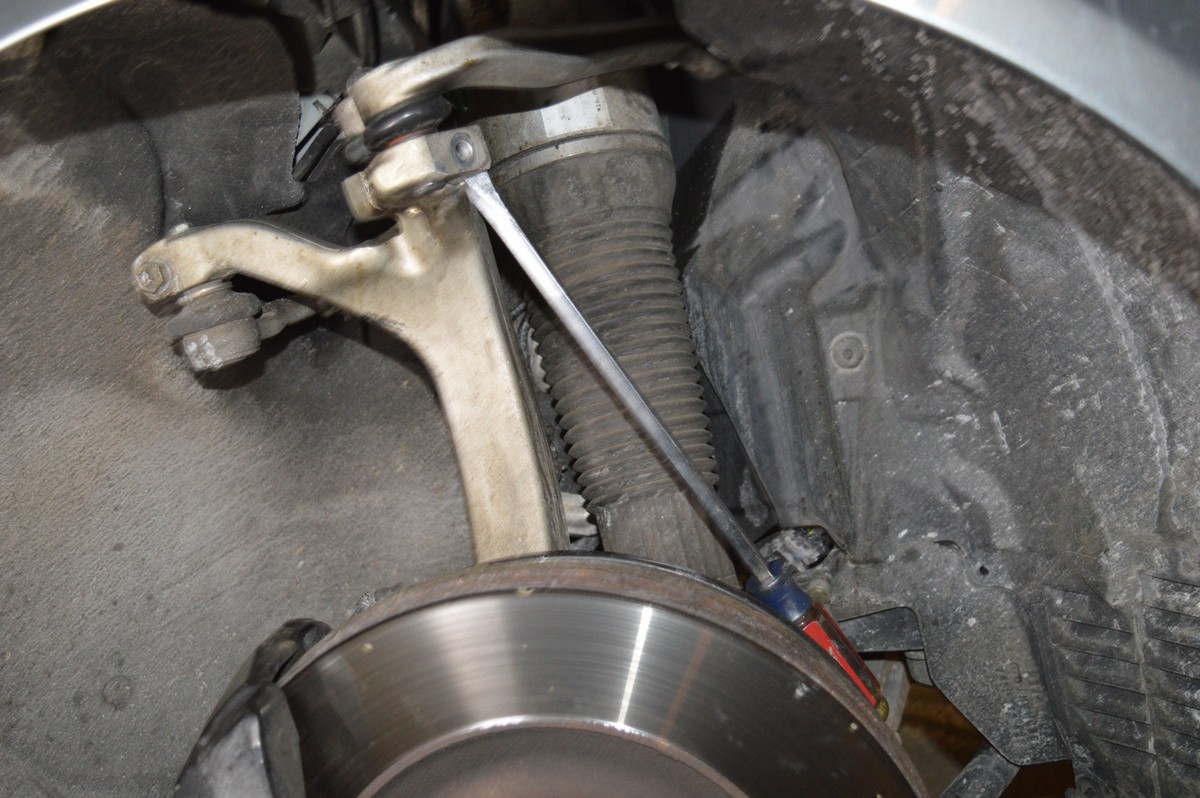
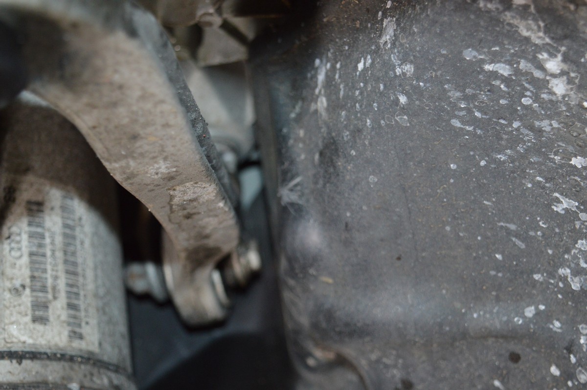
Large screwdriver driven into forward control arm pinch bolt slit to open it up, this is used for both removal and installation. The forward control arm just popped out and back in without this.
When installing the arms, I used the screw driver trick to get the forward one open again and it dropped right in.
The control arms should “jump” upwards to their originally installed factory position, if you’ve never had them out before, as in my case. What I did was mark the center of the aft control arm on the inner fender liner. This way when I put it back together and torqued them up, they would be in the same approximate position within 1/8” or so.
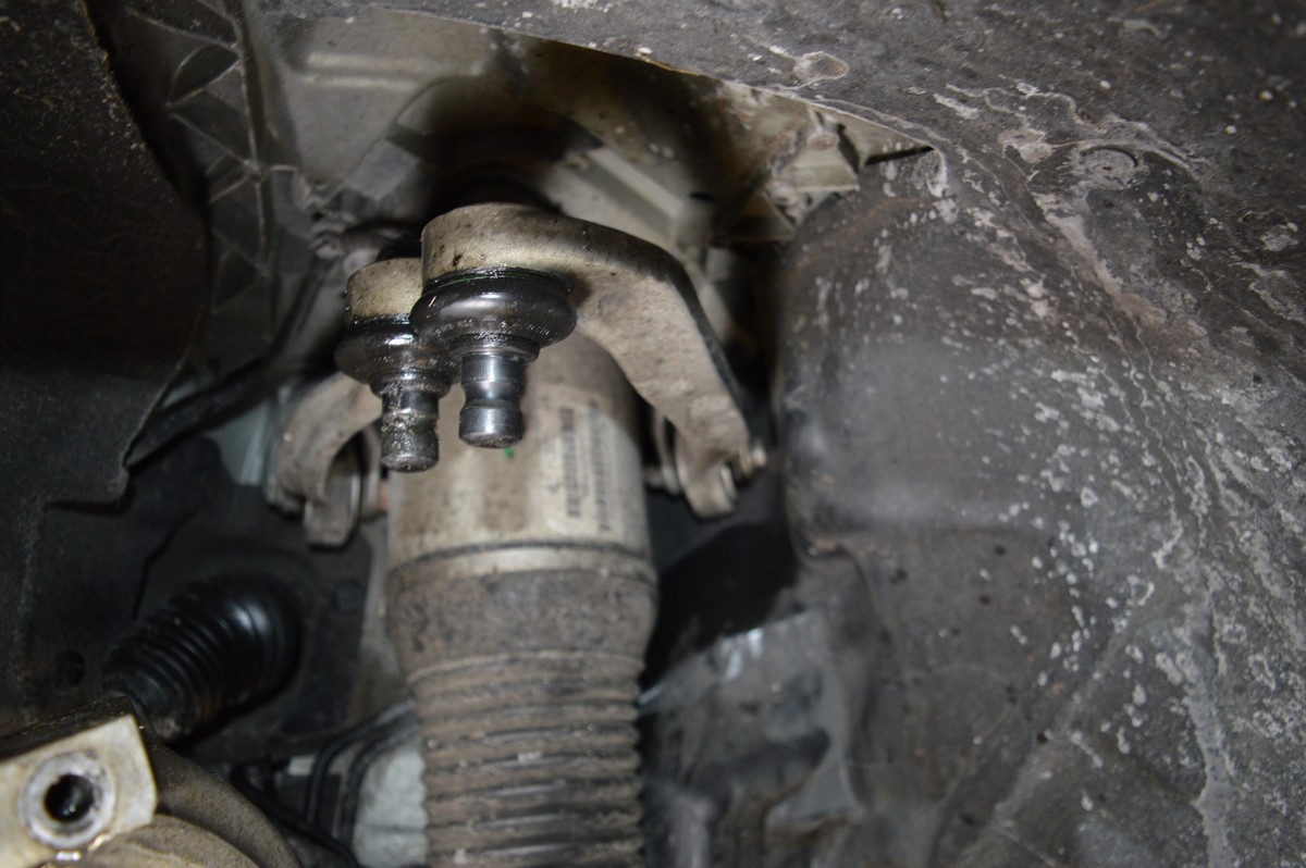
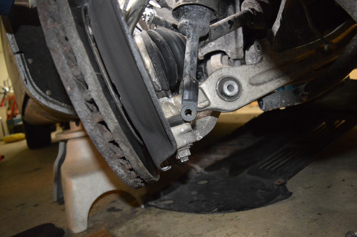
Control Arms jumped to no-load position after removal from the control arm. Look at the inner fender just forward of the right control arm, you will see where I scribed the center mark of the control arm, this will be used for final tightening position. Notice they are both at exactly the same height.
Close up of scribe position on inner fender.
Now loosen the control arm bolts on both control arms using the 16mm wrenches. Just break them loose, to the point to where they drop.
For the air strut assembly, loosen the 18mm bolt that holds it to the lower control arm. Leave the bolt in place for now.
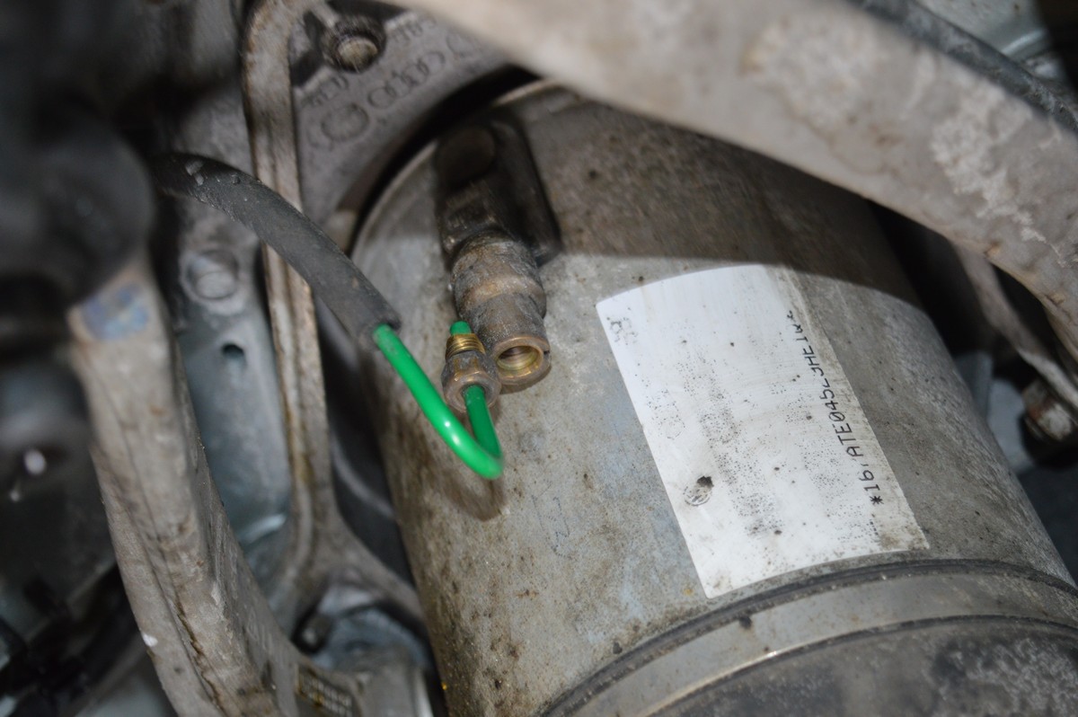
Using a 10 mm open end wrench, remove the brass connecting screw from the air line to the strut, it will vent the strut.
Up top in the engine compartment, remove the rubber strip in front of the beauty covers that cover the cowl, remove the cover for the coolant expansion tank, remove the beauty covers on both sides.
Remove the 6 mm Allen head screw that holds the electrical connector for the air strut. Disconnect the electrical connector by pushing it together and then pinching the connector and pull it apart. It should come apart VERY easily. Remove the rubber boot that the wiring goes through and push it down the hole.
This will expose the (3) air strut mounting bolts.
Left side: Two are easy to get to, the third is blocked by the coolant expansion tank black holder. Remove the (2) 10 mm nuts that hold it down, using a small pry bar, pop it up over the studs. Now you can get a small 16 mm socket on that bolt, but you’ll probably still have to pull the expansion tank back towards the fender to get the socket and extension to fit. It’s not super simple.
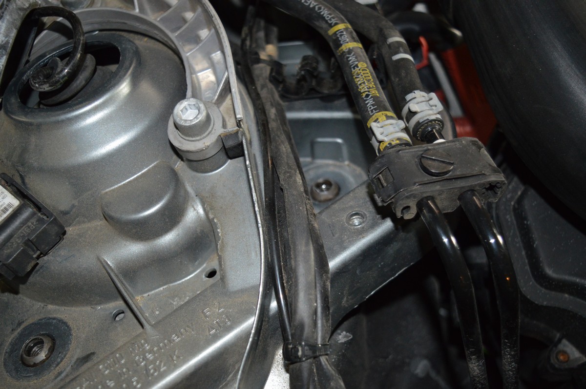
Right side: You’ll have to unscrew the small black screw that holds the fuel lines in place and pop the fuel lines out of the holder. For the bolt that is blocked by the ECU wiring harness, at least for the S8, just man handle the wiring harness up and towards the back of the car and get the 16 mm socket on the bolt.
Stuff the rubber boot and electrical wiring down past the fender hole.
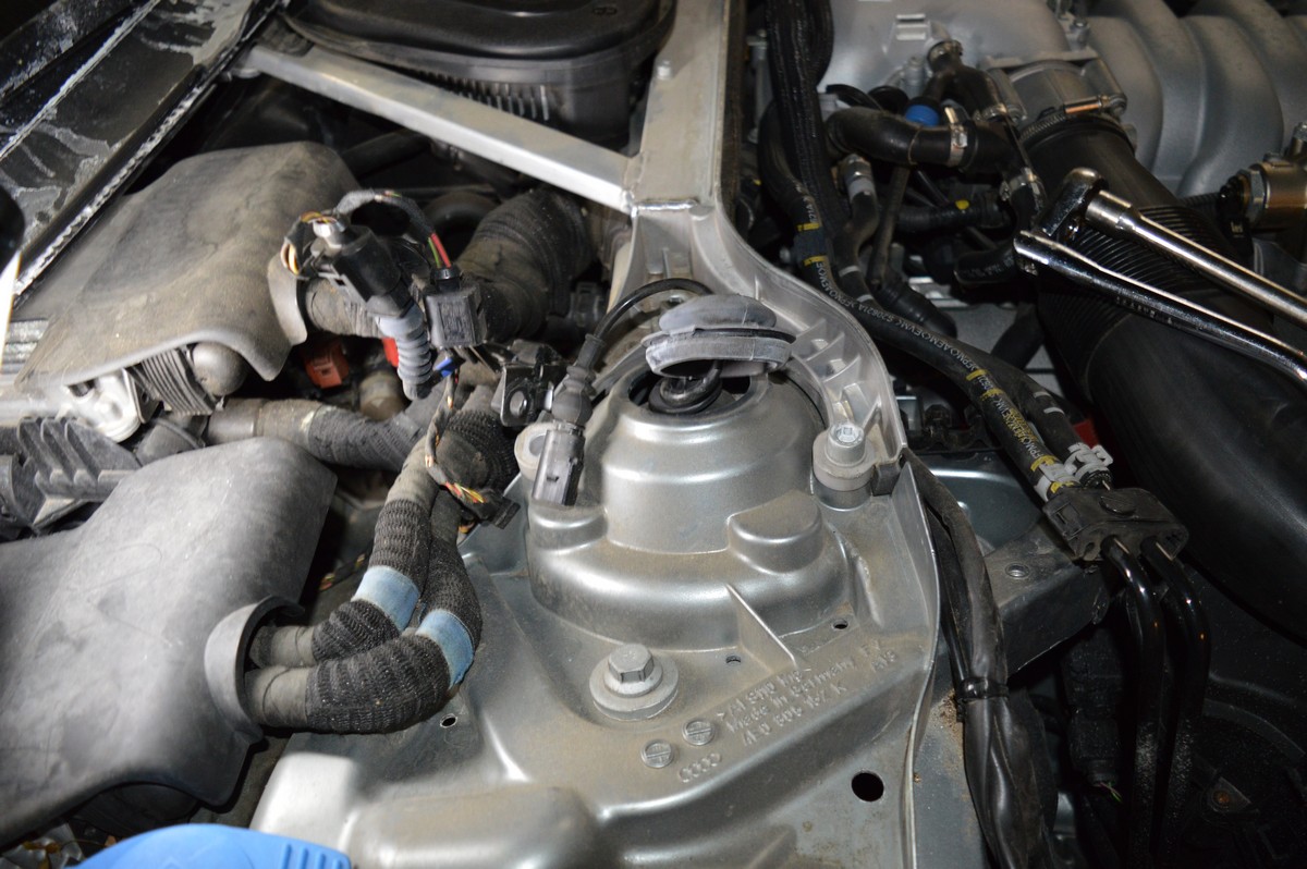
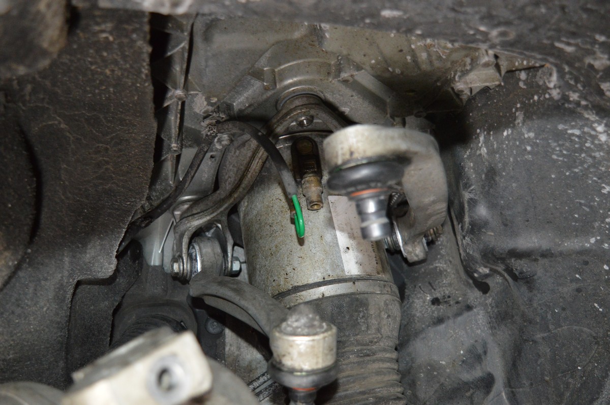
Right hand side, 6 mm Allen head screw removed for electrical connector mounting, electrical connector disconnected, rubber boot removed, and fuel lines moved out of the way.
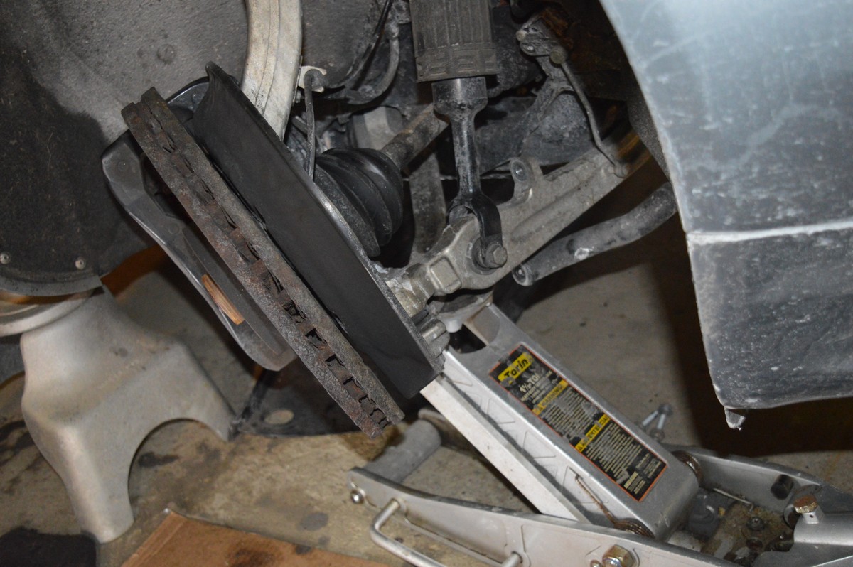
Prior to removing the upper strut bolts, PUT A JACK under the lower control arms and jack it up so to put a pre-load on the suspension, almost enough to raise that corner. This will keep the strut assembly in place when removing the bolts.
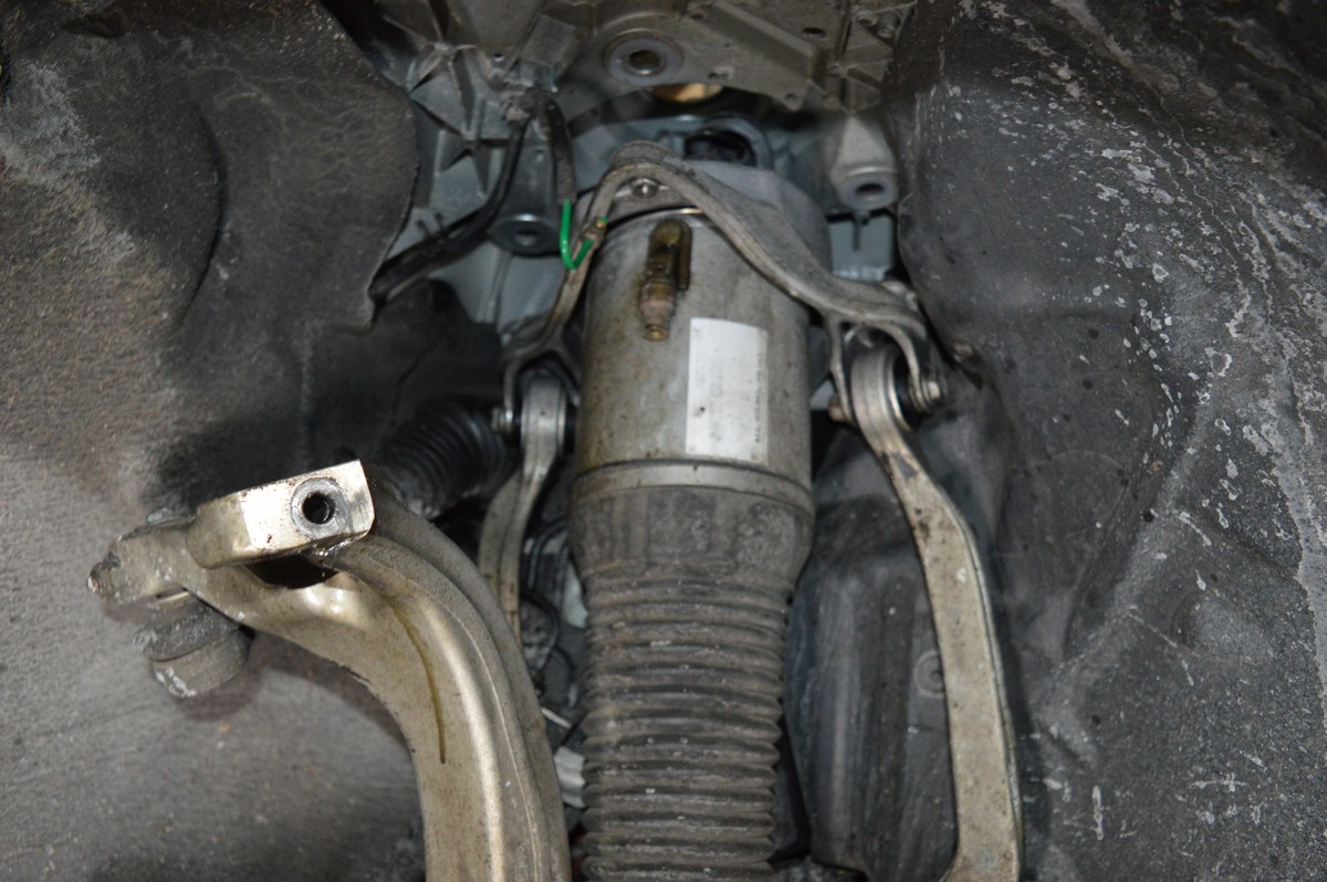
Picture above shows air strut carrier as it comes through the fender in two places (bolts are removed in this picture). Keeping the jack in place under the control arm keeps this all in place so the strut does not move during removal or assembly. This indexes the carrier shoulders in place and helps prevent cross threading of the carrier.
Spray WD-40 on the bolt ends in the wheel well at the carrier. Because they are exposed to the elements, they will be easier to get through the carrier. Using a RACHET ONLY (do not use an impact wrench) unscrew the three bolts. I would start with the difficult ones first so that the strut assembly does not ****. You do NOT want to strip any of these holes. Once all three bolts are removed, lower the jack that is pre loading the suspension. Remove the 18 mm bolt that is holding the air strut assembly to the control arm. Slide the bottom of the air strut assembly out towards the control arm ball joints. Once this is complete, you can then unbolt the control arms from inside the wheel well with the inner fender still in place.
Once the three carrier bolts are removed, remove the jack and remove the lower air strut assembly to control arm bolt. Slide the strut towards the brake rotor.
Note how the carrier assembly is free and the control arm bolts can easily be removed without removing the inner fender. Remove the control arms.
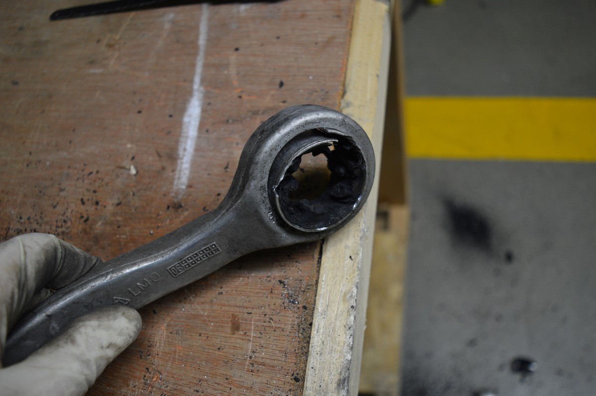
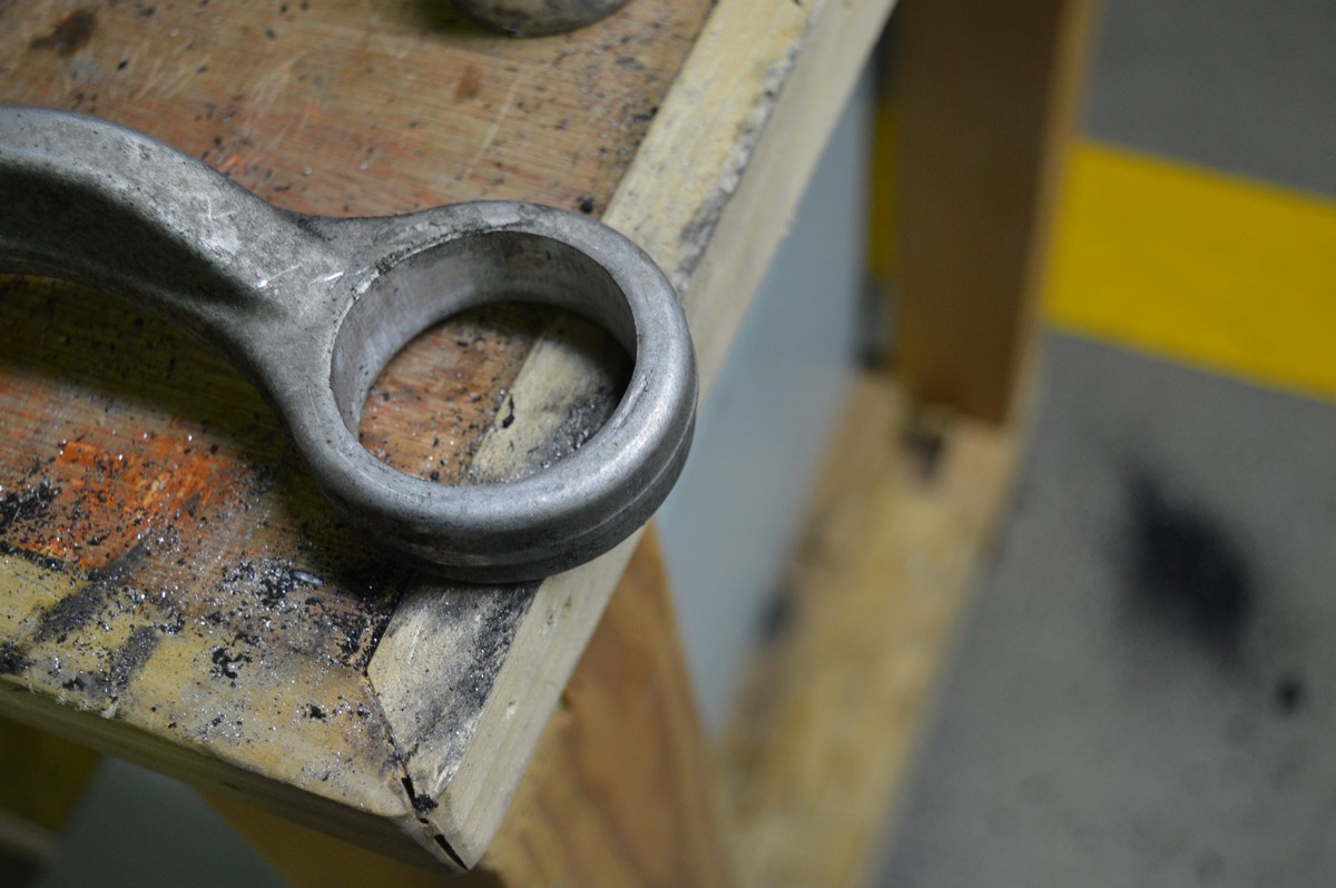
Now that the control arms are removed, all we have to do is to change out the bushings.
Bushing Replacement
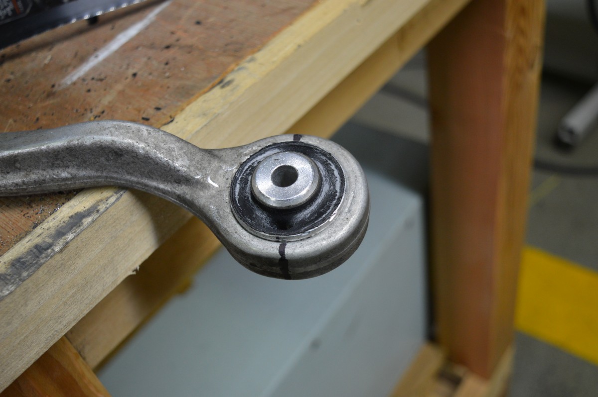
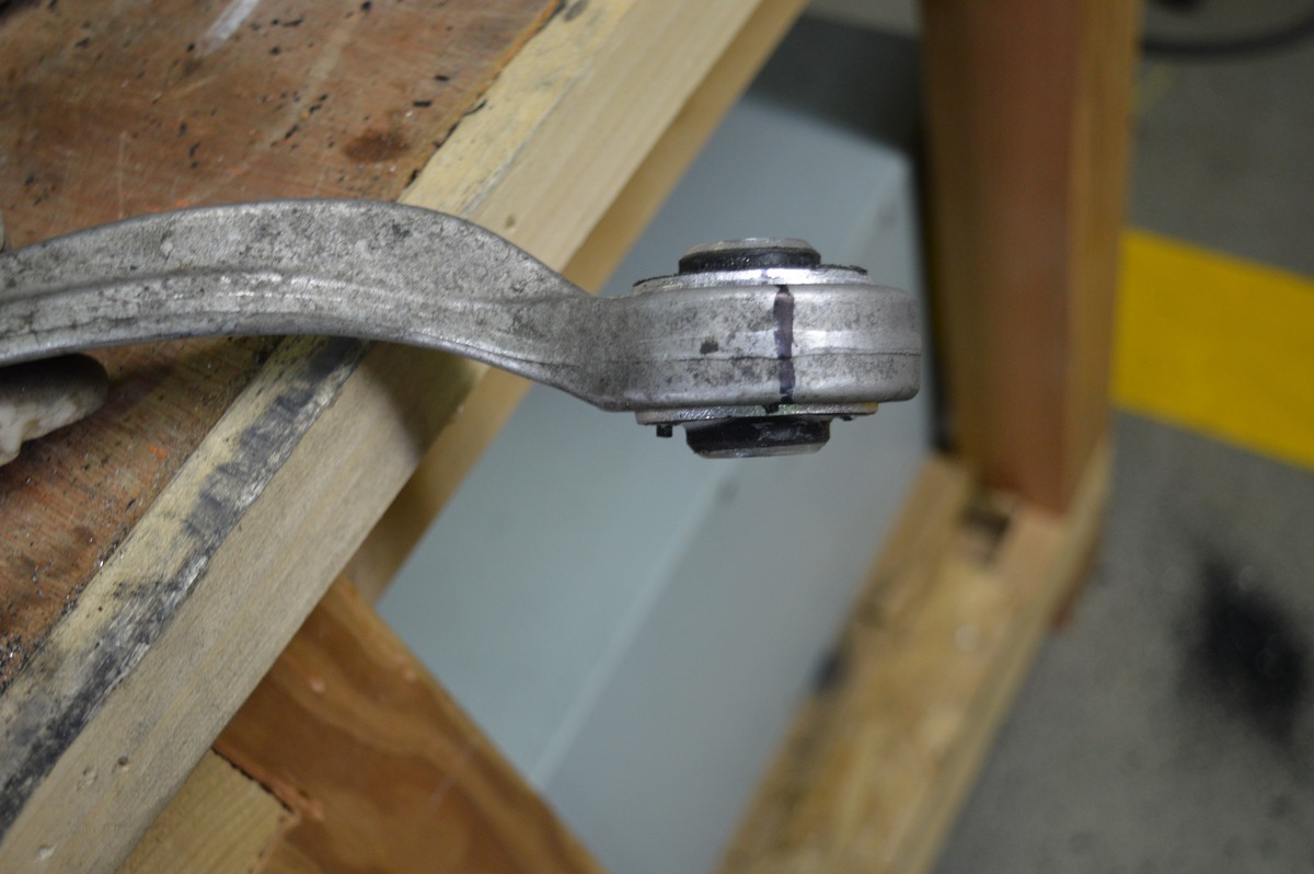
Mark the control arm bushings with a Sharpie to index where the split in the rubber should be.
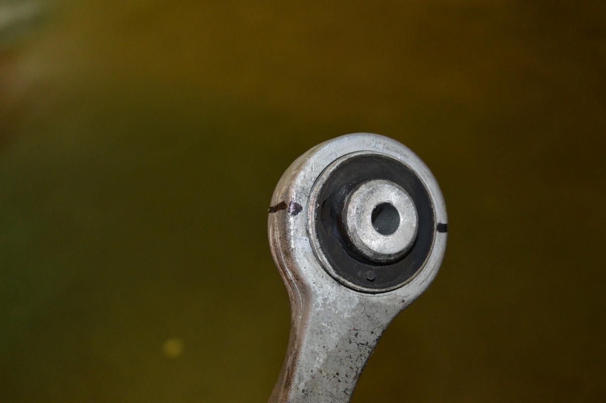
Mark where the factory split is in the rubber prior to removing the bushing so you can use this when putting the new bushings back in. Do not use brake cleaner on the control arm after marking it with a Sharpie as it will come off.
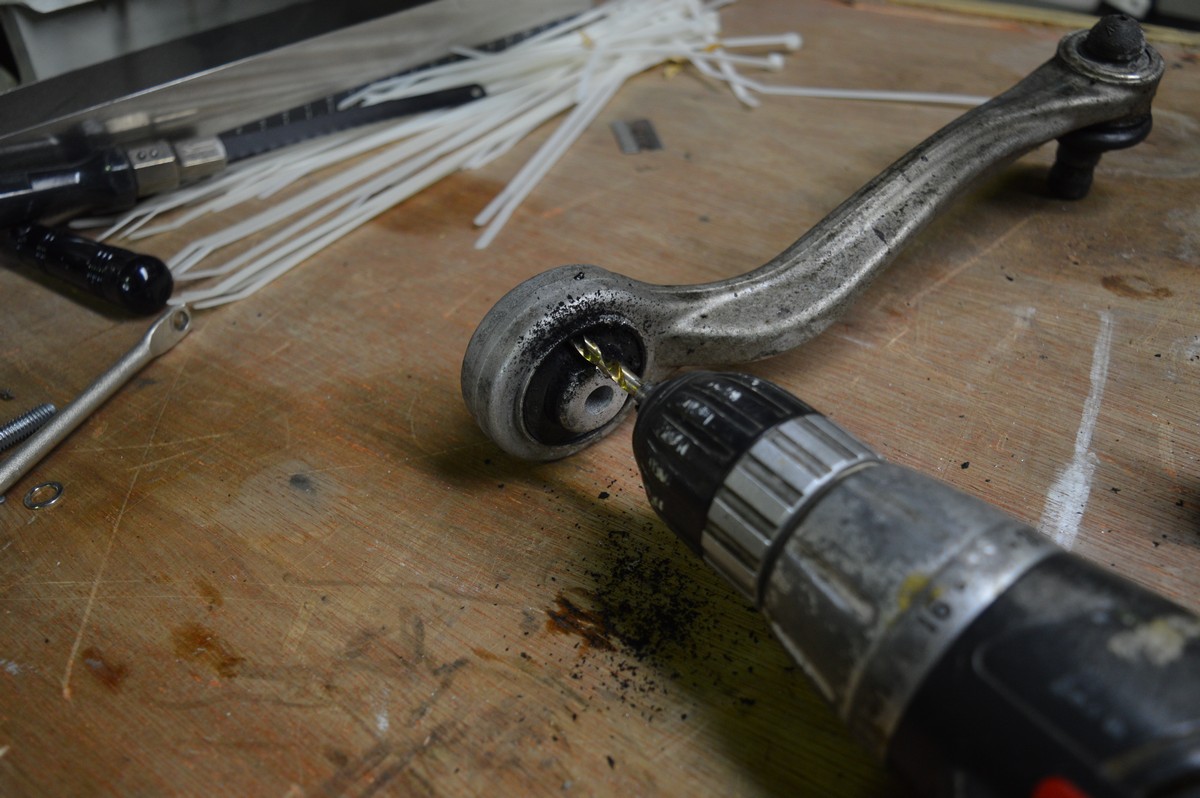
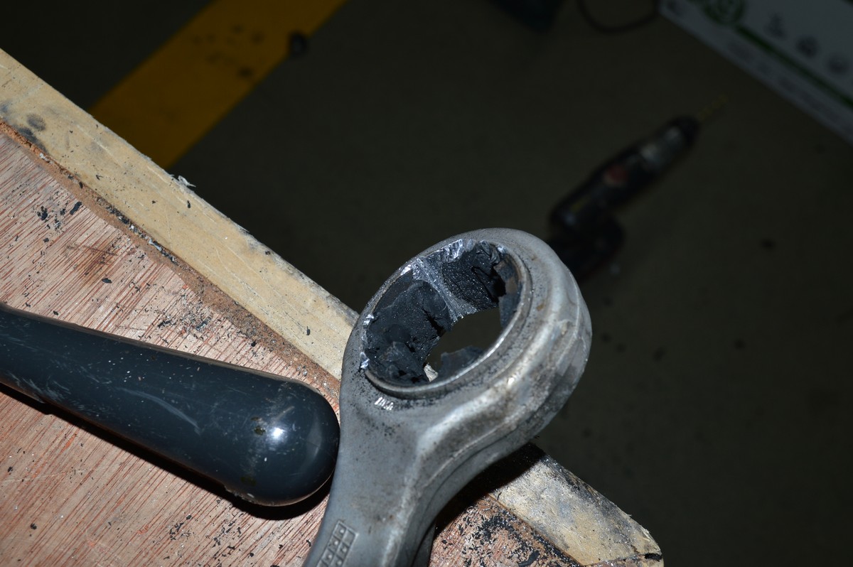
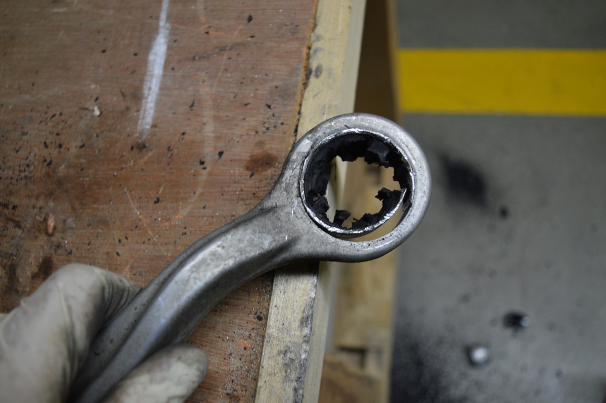
Using a drill and an approximate 1/4” or slightly small drill bit, drill the rubber out, I found the easiest way was to go in on an angle versus straight up and down, and then once it’s through, just pull it back and forth. Keep going around until you separate the inner bushing from the control arm rubber portion. If your fast (and lucky) you’ll be done in about 4-5 minutes.
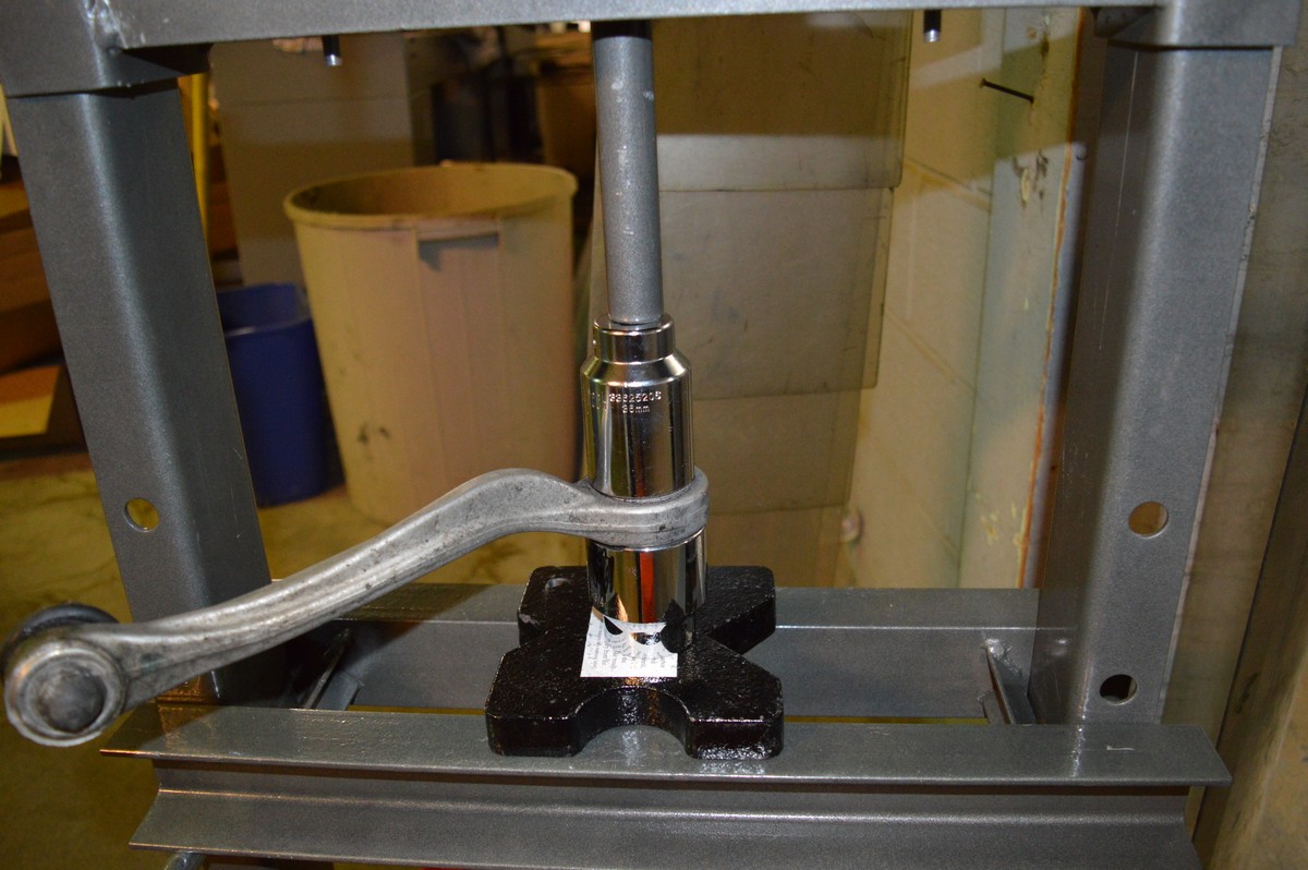
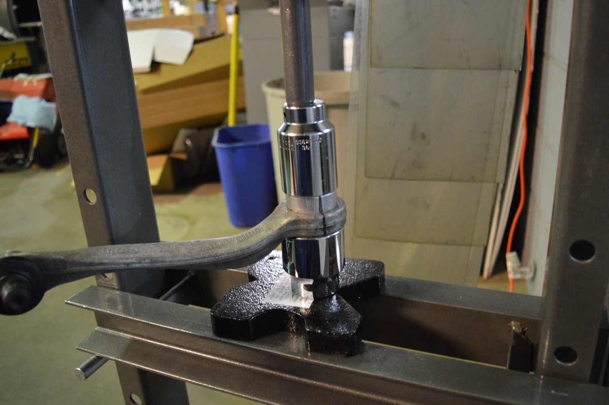
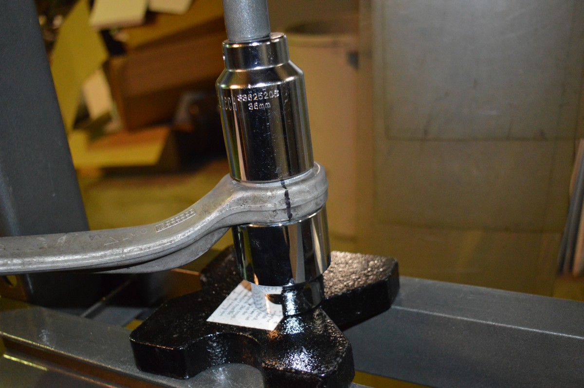
Now that it is out, I brought it over to the press to move the bushing approximately 1/8” so it was flush with the control arm on one side. This makes it easier to break once you weaken it with a hacksaw blade. Use the 36 mm socket to push on it, and the 1 3/4” or 1 13/16” socket as a receiver. I modified the receiver socket by grinding it down so I could put the control arm both up and down.
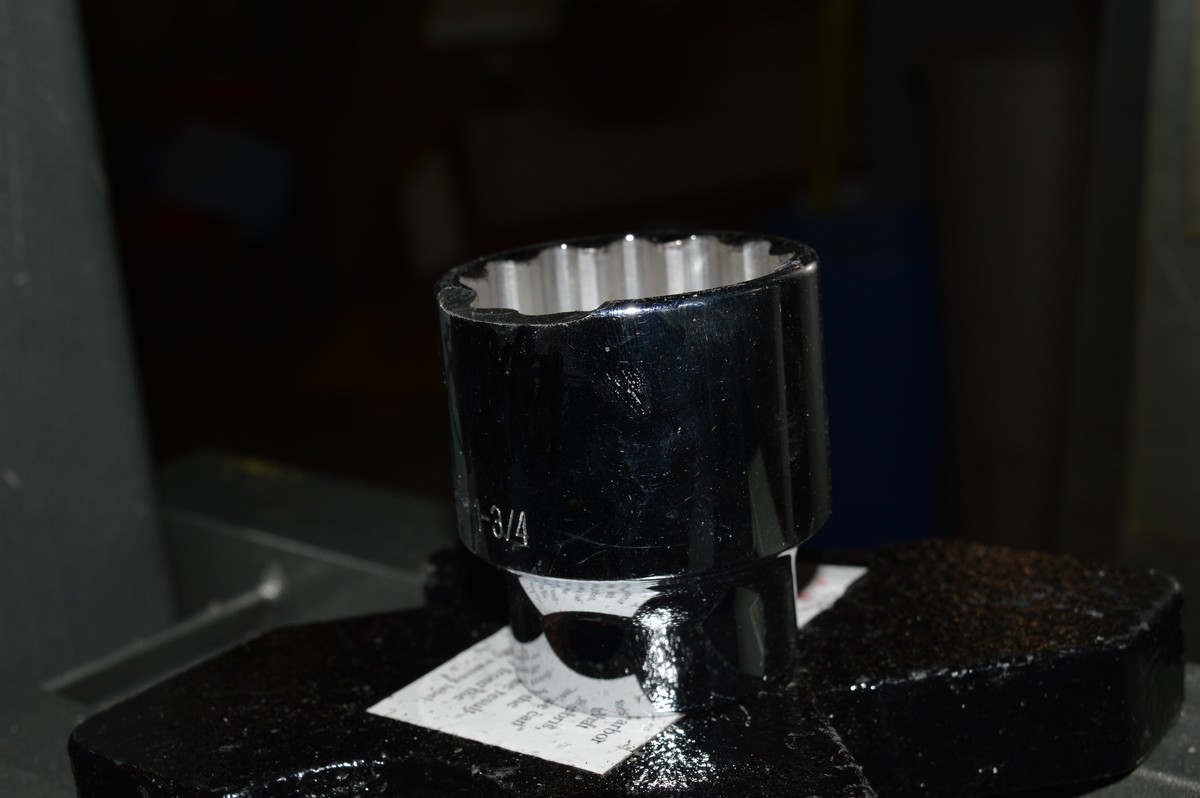
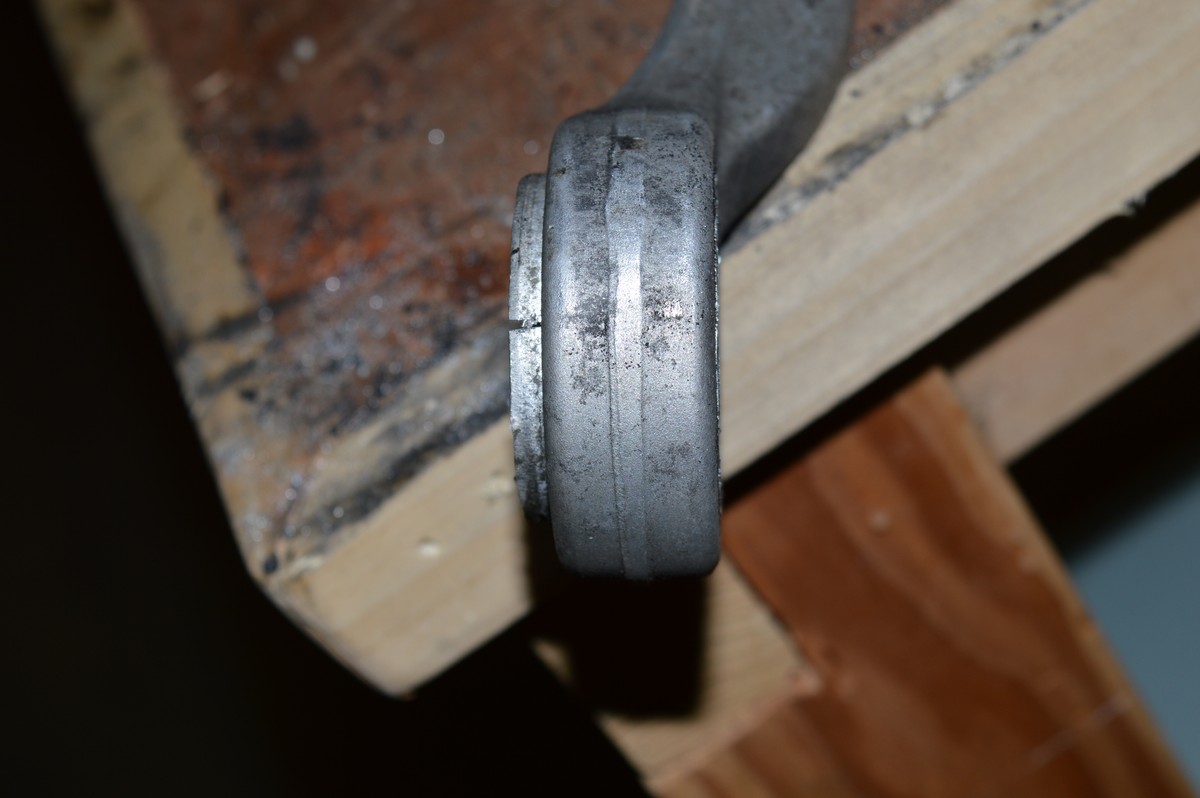
Receiver socket ground at the edge so the control arm could be placed facing down in it and the arm still clears.
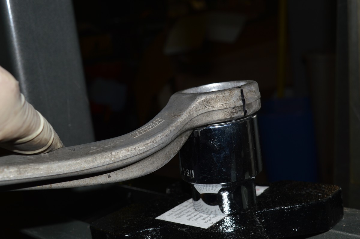
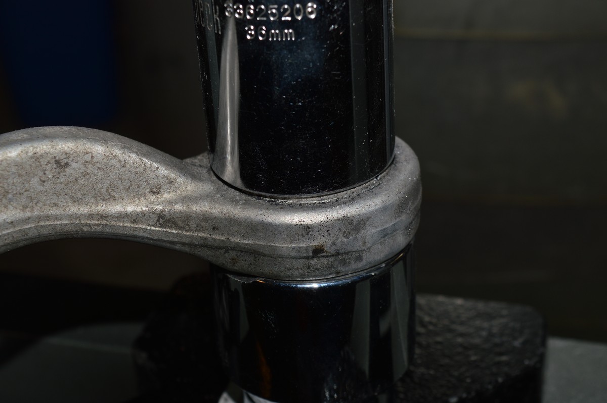
As found position of bushing, they stick out about 1/8” on each side, push the bushing to it is almost flush on one side.
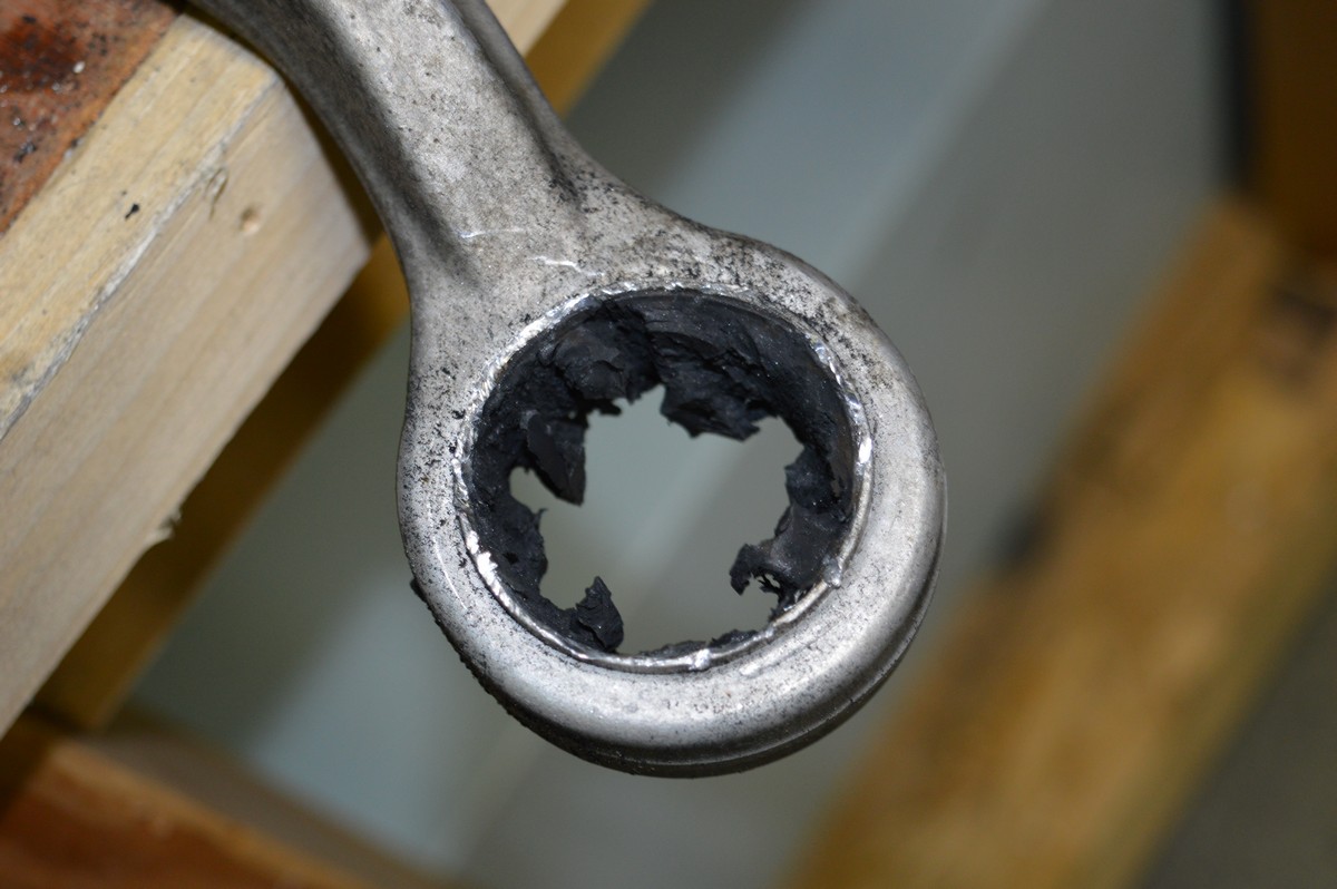
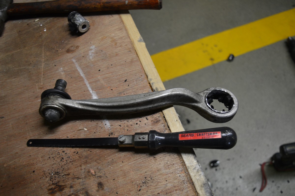
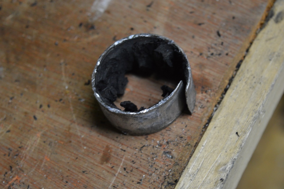
Using a hacksaw blade on a handle, cut through the rubber and start notching the bushing. It is thin, don’t cut through it. Once you get a good notch in it, use a large flat blade screwdriver and a hammer to strike it adjacent to the cut and it should break it. If it doesn’t after a few blows, cut it some more. Then you can just remove it with your hands.
I found it easiest if I used some 120 grit sandpaper to open the control arm a very small amount. I did it in the direction that that the bushing goes in the control arm. Clean it with a cloth (but not brake cleaner as your marks on the control arm will be washed away! If this happens, you can always index it to the other control arm). Mark the new bushing with a Sharpie so it matches where the rubber is cut out. This will allow you to index everything up when pressing it in. Prior to pressing the bushing in, you’ll need to make is somewhat round. Using a pair of calipers, find the thick part of it, and then using a hammer, strike that portion on a vice or other hard surface. Measure again and get it close to round before installation.
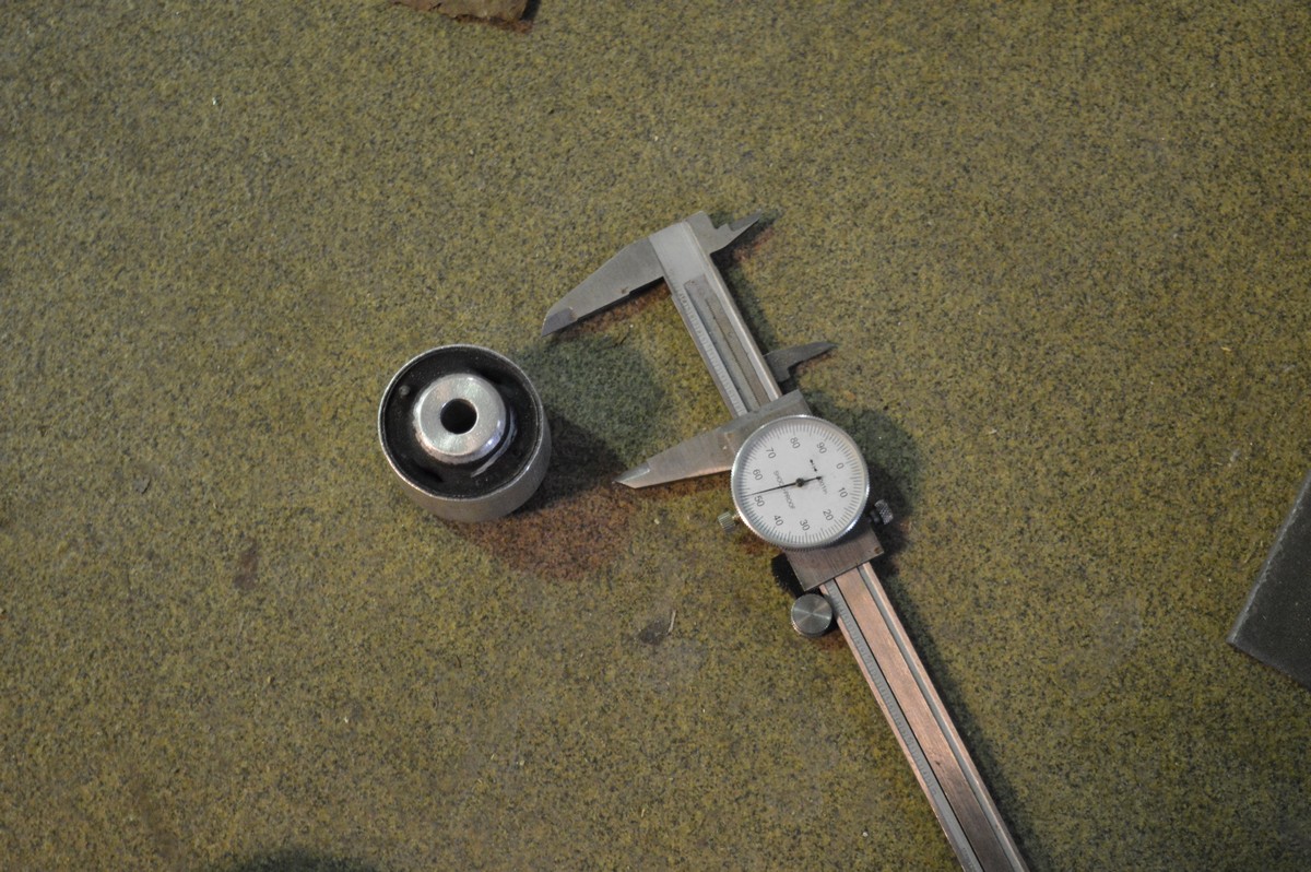
The bushings does not come from the factory round. Using a pair of calipers it’s easy to find the oblong widest part, compare it with 90 degrees from that, then put it on a hard surface and hit with a hammer to get it close to round, measure and repeat.
Starting it can be tricky. I was able to use a rubber mallet and get a few started, a few I started on the press. Using the sandpaper really made a difference for the bushing to start, doesn’t take much. Press it in until it’s standing proud just a bit, pull it out before it goes too far, check to see if each side is equidistant, if not, adjust the appropriate side to get it there.
Note the Sharpie mark on the bushing indexing where the slit in the rubber is, index this to the control arm mark. Push the bushing in with the press. If it’s not moving and you are increasing force significantly, stop and figure out why it’s not going in. It should press in with a relatively small amount of force.
Installation
There are a few tricks with installation. The most important is NOT TO CROSS THREAD the upper strut assembly bolts into the carrier. You have to be careful. If it’s hard to thread it in, stand back, and access what is going on. Pre-loading the strut assembly so it’s hard up against the fender is the easiest way to get this right. Install and tighten the control arms so they can be easily moved but just don’t flop in the breeze. DO NOT tighten them down yet. Move the air strut assembly back into its normal position, start the 18 mm bolt at the lower control arm, do not tighten. Put the jack under the lower control arm and start raising it so it raises the air strut assembly up to the fender, ensure you thread the wiring harness and rubber grommet up through the hole. Once it is close, look at the carrier assembly and index it to the holes. Continue lifting the jack and get all three carrier collars up into the fender holes. Put some pressure on the jack to keep it in this position. This will ensure that the strut assembly is sitting correctly and this makes it much easier to get the three bolts in straight. Start and thread each of the three bolts. DO NOT USE an impact wrench on this, you could easily cross thread them.
Use the jack to place the air strut assembly carrier in place. Ensure the shoulders of the carrier are properly seated by inspecting them from the bottom and top prior to threading the bolts back in.
Using the jack, you can raise or lower the suspension as required to get the control arms back into the upright and install the pinch bolt. I used the large screw driver to open the forward pinch bolt location to get the control arm in, it just dropped in then. Torque the pinch bolt. Once they are installed, we are going to tighten the control arms in the correctly indexed positon so that there is the correct pre load on them. Jack the suspension up so that the index mark that you made on inner fender is in the center of the aft control arm. Once it is place, use the 16 mm wrenches and torque the control arms down. They will both be positioned at exactly the same angle because both are in the upright, locked down with the pinch bolt. They will both have exactly the same amount of pre-load on them. With the suspension still under load from the jack, tighten the lower control arm air strut 18 mm bolt.
You can now remove the jack from the lower control arm.
Install the air strut brass nut.
To install the sway bar link, I installed the bolt into the sway bar end first a few turns, then using a jack under the sway bar, line up the bolt and get it through the hole and put the nut on it. If you do it the other way around, you could cross thread the sway bar if you are not perfectly straight. Up to you how you want to do it. Button up everything that I missed in this procedure. Install beauty cover in the engine compartment. Make sure you put the wheels back on! Enjoy your tighter A8 or S8!
Replacing the upper control arm bushings on the D3 Audi A8 and S8 isn't hard, but I would consider it a more advanced repair job, not a simple DIY. The best advice I could give would be to go slow and take your time. There are only a few things you can screw up, but it's best when you get it right without any issues.
I decided to do this after owning my S8 5 years, it had 80K miles on it and I was getting a more pronounced "clunk" in the front suspension, especially on the left hand side when I would have the wheel turned hard right and going up a large incline, like turning into a parking lot with a small ramp going into it. That is now gone.
For about $250 including tools, I was able to rebuild all four upper links and replace the sway bar links. Included in this is the $110 I spent at Harbor Freight Tools for the 12 tons press. So pretty darn cheap, and I enjoyed doing the work. I spent about 10-11 hours doing this over two days. The first side was longer, the second side was a walk in the park, about 3 hours.
Here are my notes and some pictures, there are many ways to do this, this is mine and found it to be easy once I figured it out and used this procedure on the second side.
Tools Required
Jack Stands
Jack
14 mm ratcheting wrench that pivots or ratchet with 14 mm socket
14 mm combination wrench
16 mm ratcheting wrench that pivots
16 mm combination wrench
18 mm ratcheting wrench that pivots
18 mm combination wrench
10 mm open wrench
16mm socket wrench, both a deep well and standard short socket
Large screwdriver to pry the control arm pinch points open
Press if you plan to press the bushings in and out yourself
36 mm socket to press the bushing in
1 3/4" or 1 13/16" socket to receive the control arm during the pressing process
Drill
Drill bit to drill out the rubber, 1/4" or slightly smaller
Hacksaw blade and handle to mount the blade in to cut the bushing
Calipers to measure bushing to get it round
Other standard tools and wrenches
I would not try this job without the ratcheting wrenches that pivot. This is for tightening of the control arms after they are installed. I really don't know how you would do it without them. The control arm is 16 mm, and the air strut assembly to lower control arm is 18 mm, you don't need this one, but it sure is nice. These are from GearWrench 85288 12 Piece X-Beam Metric Flex Combination Ratcheting Wrench Set. A great addition to your tool box!
Parts Needed
Pinch bolt and nut
Control Arm Bushings, Lemforder Part Number 29318 01, Audi 8D0 407 515 C, note that these are specifically for the A8, but I used them on my S8.
Sway Bar Links (if replacing them), Lemforder Part Number 30536 01, Audi 4E0 411 317 E
Inner fender plastic push pins if removing the inner fender (this procedure does not have you remove it), quantity 10, 5 per side.
Lemforder bushings, there were two in a package when I ordered them from Rockauto.com, about $10 each.
This thread has so much information on it regarding these parts, please look it over:
https://www.audiworld.com/forums/a8-...ences-2874055/
Procedure
This procedure shows the right hand side, but almost all is the same for the left hand side with exception of getting to the top side air strut assembly mounting bolt, you just have to move the coolant expansion tank for the left hand side, just a bit.
I DID NOT remove the inner fender for the right hand side, but did for the left hand side. I’m sure you could do it on the left hand side without removing it, but since I didn’t do it that way, I’m not 100% sure.
Put the car up on jack stands.
Remove the wheels.
Unbolt the sway bar link from the control arm, I replaced these with new Lemorder units (OEM supplier) that I bought on ebay for about $26 each, great deal!
Remove the upright pinch bolt. Hopefully you won’t have trouble with this. Once you have the nut off and it’s spinning, I used an electric impact driver to turn it, then used a small pry lever to push on the end with the nut to get it moving in the correct direction (out). Once you get it out an inch or two, put a 14mm closed end wrench on the bolt head side, drop it over the head and then pull on it while using the impact driver to get the bolt out. REPLACE BOLT AND NUT.
Now you have to get the control arm out of the upright. Spray the pinch bolt assembly with WD-40, it will help the control arms come out easier.
The short one (aft) was relatively easy to pop out on both sides. For the long one (forward), I put a large screw driver in the pinch area and tapped it with a hammer to open it up slightly (SEE WARNINGS ABOUT DOING THIS IN REPLY 2 & 3 BELOW, it is not recommended, but worked for me), then using a rubber mallet, just hit the control arm upwards and out it popped.
Large screwdriver driven into forward control arm pinch bolt slit to open it up, this is used for both removal and installation. The forward control arm just popped out and back in without this.
When installing the arms, I used the screw driver trick to get the forward one open again and it dropped right in.
The control arms should “jump” upwards to their originally installed factory position, if you’ve never had them out before, as in my case. What I did was mark the center of the aft control arm on the inner fender liner. This way when I put it back together and torqued them up, they would be in the same approximate position within 1/8” or so.
Control Arms jumped to no-load position after removal from the control arm. Look at the inner fender just forward of the right control arm, you will see where I scribed the center mark of the control arm, this will be used for final tightening position. Notice they are both at exactly the same height.
Close up of scribe position on inner fender.
Now loosen the control arm bolts on both control arms using the 16mm wrenches. Just break them loose, to the point to where they drop.
For the air strut assembly, loosen the 18mm bolt that holds it to the lower control arm. Leave the bolt in place for now.
Using a 10 mm open end wrench, remove the brass connecting screw from the air line to the strut, it will vent the strut.
Up top in the engine compartment, remove the rubber strip in front of the beauty covers that cover the cowl, remove the cover for the coolant expansion tank, remove the beauty covers on both sides.
Remove the 6 mm Allen head screw that holds the electrical connector for the air strut. Disconnect the electrical connector by pushing it together and then pinching the connector and pull it apart. It should come apart VERY easily. Remove the rubber boot that the wiring goes through and push it down the hole.
This will expose the (3) air strut mounting bolts.
Left side: Two are easy to get to, the third is blocked by the coolant expansion tank black holder. Remove the (2) 10 mm nuts that hold it down, using a small pry bar, pop it up over the studs. Now you can get a small 16 mm socket on that bolt, but you’ll probably still have to pull the expansion tank back towards the fender to get the socket and extension to fit. It’s not super simple.
Right side: You’ll have to unscrew the small black screw that holds the fuel lines in place and pop the fuel lines out of the holder. For the bolt that is blocked by the ECU wiring harness, at least for the S8, just man handle the wiring harness up and towards the back of the car and get the 16 mm socket on the bolt.
Stuff the rubber boot and electrical wiring down past the fender hole.
Right hand side, 6 mm Allen head screw removed for electrical connector mounting, electrical connector disconnected, rubber boot removed, and fuel lines moved out of the way.
Prior to removing the upper strut bolts, PUT A JACK under the lower control arms and jack it up so to put a pre-load on the suspension, almost enough to raise that corner. This will keep the strut assembly in place when removing the bolts.
Picture above shows air strut carrier as it comes through the fender in two places (bolts are removed in this picture). Keeping the jack in place under the control arm keeps this all in place so the strut does not move during removal or assembly. This indexes the carrier shoulders in place and helps prevent cross threading of the carrier.
Spray WD-40 on the bolt ends in the wheel well at the carrier. Because they are exposed to the elements, they will be easier to get through the carrier. Using a RACHET ONLY (do not use an impact wrench) unscrew the three bolts. I would start with the difficult ones first so that the strut assembly does not ****. You do NOT want to strip any of these holes. Once all three bolts are removed, lower the jack that is pre loading the suspension. Remove the 18 mm bolt that is holding the air strut assembly to the control arm. Slide the bottom of the air strut assembly out towards the control arm ball joints. Once this is complete, you can then unbolt the control arms from inside the wheel well with the inner fender still in place.
Once the three carrier bolts are removed, remove the jack and remove the lower air strut assembly to control arm bolt. Slide the strut towards the brake rotor.
Note how the carrier assembly is free and the control arm bolts can easily be removed without removing the inner fender. Remove the control arms.
Now that the control arms are removed, all we have to do is to change out the bushings.
Bushing Replacement
Mark the control arm bushings with a Sharpie to index where the split in the rubber should be.
Mark where the factory split is in the rubber prior to removing the bushing so you can use this when putting the new bushings back in. Do not use brake cleaner on the control arm after marking it with a Sharpie as it will come off.
Using a drill and an approximate 1/4” or slightly small drill bit, drill the rubber out, I found the easiest way was to go in on an angle versus straight up and down, and then once it’s through, just pull it back and forth. Keep going around until you separate the inner bushing from the control arm rubber portion. If your fast (and lucky) you’ll be done in about 4-5 minutes.
Now that it is out, I brought it over to the press to move the bushing approximately 1/8” so it was flush with the control arm on one side. This makes it easier to break once you weaken it with a hacksaw blade. Use the 36 mm socket to push on it, and the 1 3/4” or 1 13/16” socket as a receiver. I modified the receiver socket by grinding it down so I could put the control arm both up and down.
Receiver socket ground at the edge so the control arm could be placed facing down in it and the arm still clears.
As found position of bushing, they stick out about 1/8” on each side, push the bushing to it is almost flush on one side.
Using a hacksaw blade on a handle, cut through the rubber and start notching the bushing. It is thin, don’t cut through it. Once you get a good notch in it, use a large flat blade screwdriver and a hammer to strike it adjacent to the cut and it should break it. If it doesn’t after a few blows, cut it some more. Then you can just remove it with your hands.
I found it easiest if I used some 120 grit sandpaper to open the control arm a very small amount. I did it in the direction that that the bushing goes in the control arm. Clean it with a cloth (but not brake cleaner as your marks on the control arm will be washed away! If this happens, you can always index it to the other control arm). Mark the new bushing with a Sharpie so it matches where the rubber is cut out. This will allow you to index everything up when pressing it in. Prior to pressing the bushing in, you’ll need to make is somewhat round. Using a pair of calipers, find the thick part of it, and then using a hammer, strike that portion on a vice or other hard surface. Measure again and get it close to round before installation.
The bushings does not come from the factory round. Using a pair of calipers it’s easy to find the oblong widest part, compare it with 90 degrees from that, then put it on a hard surface and hit with a hammer to get it close to round, measure and repeat.
Starting it can be tricky. I was able to use a rubber mallet and get a few started, a few I started on the press. Using the sandpaper really made a difference for the bushing to start, doesn’t take much. Press it in until it’s standing proud just a bit, pull it out before it goes too far, check to see if each side is equidistant, if not, adjust the appropriate side to get it there.
Note the Sharpie mark on the bushing indexing where the slit in the rubber is, index this to the control arm mark. Push the bushing in with the press. If it’s not moving and you are increasing force significantly, stop and figure out why it’s not going in. It should press in with a relatively small amount of force.
Installation
There are a few tricks with installation. The most important is NOT TO CROSS THREAD the upper strut assembly bolts into the carrier. You have to be careful. If it’s hard to thread it in, stand back, and access what is going on. Pre-loading the strut assembly so it’s hard up against the fender is the easiest way to get this right. Install and tighten the control arms so they can be easily moved but just don’t flop in the breeze. DO NOT tighten them down yet. Move the air strut assembly back into its normal position, start the 18 mm bolt at the lower control arm, do not tighten. Put the jack under the lower control arm and start raising it so it raises the air strut assembly up to the fender, ensure you thread the wiring harness and rubber grommet up through the hole. Once it is close, look at the carrier assembly and index it to the holes. Continue lifting the jack and get all three carrier collars up into the fender holes. Put some pressure on the jack to keep it in this position. This will ensure that the strut assembly is sitting correctly and this makes it much easier to get the three bolts in straight. Start and thread each of the three bolts. DO NOT USE an impact wrench on this, you could easily cross thread them.
Use the jack to place the air strut assembly carrier in place. Ensure the shoulders of the carrier are properly seated by inspecting them from the bottom and top prior to threading the bolts back in.
Using the jack, you can raise or lower the suspension as required to get the control arms back into the upright and install the pinch bolt. I used the large screw driver to open the forward pinch bolt location to get the control arm in, it just dropped in then. Torque the pinch bolt. Once they are installed, we are going to tighten the control arms in the correctly indexed positon so that there is the correct pre load on them. Jack the suspension up so that the index mark that you made on inner fender is in the center of the aft control arm. Once it is place, use the 16 mm wrenches and torque the control arms down. They will both be positioned at exactly the same angle because both are in the upright, locked down with the pinch bolt. They will both have exactly the same amount of pre-load on them. With the suspension still under load from the jack, tighten the lower control arm air strut 18 mm bolt.
You can now remove the jack from the lower control arm.
Install the air strut brass nut.
To install the sway bar link, I installed the bolt into the sway bar end first a few turns, then using a jack under the sway bar, line up the bolt and get it through the hole and put the nut on it. If you do it the other way around, you could cross thread the sway bar if you are not perfectly straight. Up to you how you want to do it. Button up everything that I missed in this procedure. Install beauty cover in the engine compartment. Make sure you put the wheels back on! Enjoy your tighter A8 or S8!
Last edited by PaulW; 12-31-2017 at 04:34 AM.
 12-30-2017, 08:04 PM
#2
AudiWorld Super User

Thanks for contributing the hands on write up.
If I followed, it seems like you were getting very close to removing the struts. I just drop the upper plate (to which the strut and the control arms bolt) with all the strut fastening still in place. Undoing the sway bar link together with a screwdriver pry at the plate is what it takes for me to get at those inner control arm bolts. Then with the fender liner off I just pull the inner control arm bolts and take them out, with no dismounting or loosening of anything else in the air strut assembly. The W12 has the same painful upper plate bolt access up by one of the ECU's on the passenger side, and another one tangled up with the coolant reservoir on the driver's side. My reply 17 to my own earlier parts thread you mentioned covers how I do this part, including a picture of my Craftsman screwdriver and the strut air lines (and all else) still in place: https://www.audiworld.com/forums/a8-...ences-2874055/
I also would not put the screwdriver into the ball joint slot to pry at all. If the shaft of the ball joint end is stuck, it should be possible just to drive it out with the head of something like a deep reach 10mm socket and a mallet. It may just be stuck because the steering knuckle rotates a bit and leave it under some side tension; in that case just some back and forth manhandling on the steering knuckle and the control arm springs up. If bushings fully torn out like yours sort of looked, then driving it out with the 10mm socket may still be needed. The whole steering knuckle is forged, and if any part of those ears break off it is all over and an entire steering knuckle pull then follows. Often at a horrible time given the suspension is apart so getting force on the CV axle nut at many, many hundred ft. pounds of torque is really painful. Several members have snapped one of those, usually tied to a stuck pinch bolt where they start prying or pounding. Leads to many hundred dollars more even w/ junkyard parts, and car laid up waiting days + for parts.
My nits/suggestions aside, again thanks for the contributions documenting so much of it, especially with the press additions. I never did get to the bushing press out and back in stage, though worked on some ideas to do it in lieu of a regular press. Here in SF Bay Area machine shops are almost all gone, so almost only way to do it without complete arms is to buy the Harbor Freight type press like you did.
If I followed, it seems like you were getting very close to removing the struts. I just drop the upper plate (to which the strut and the control arms bolt) with all the strut fastening still in place. Undoing the sway bar link together with a screwdriver pry at the plate is what it takes for me to get at those inner control arm bolts. Then with the fender liner off I just pull the inner control arm bolts and take them out, with no dismounting or loosening of anything else in the air strut assembly. The W12 has the same painful upper plate bolt access up by one of the ECU's on the passenger side, and another one tangled up with the coolant reservoir on the driver's side. My reply 17 to my own earlier parts thread you mentioned covers how I do this part, including a picture of my Craftsman screwdriver
and the strut air lines (and all else) still in place: https://www.audiworld.com/forums/a8-...ences-2874055/I also would not put the screwdriver into the ball joint slot to pry at all. If the shaft of the ball joint end is stuck, it should be possible just to drive it out with the head of something like a deep reach 10mm socket and a mallet. It may just be stuck because the steering knuckle rotates a bit and leave it under some side tension; in that case just some back and forth manhandling on the steering knuckle and the control arm springs up. If bushings fully torn out like yours sort of looked, then driving it out with the 10mm socket may still be needed. The whole steering knuckle is forged, and if any part of those ears break off it is all over and an entire steering knuckle pull then follows. Often at a horrible time given the suspension is apart so getting force on the CV axle nut at many, many hundred ft. pounds of torque is really painful. Several members have snapped one of those, usually tied to a stuck pinch bolt where they start prying or pounding. Leads to many hundred dollars more even w/ junkyard parts, and car laid up waiting days + for parts.
My nits/suggestions aside, again thanks for the contributions documenting so much of it, especially with the press additions. I never did get to the bushing press out and back in stage, though worked on some ideas to do it in lieu of a regular press. Here in SF Bay Area machine shops are almost all gone, so almost only way to do it without complete arms is to buy the Harbor Freight type press like you did.
Last edited by MP4.2+6.0; 12-30-2017 at 08:35 PM.
12-30-2017, 09:08 PM
#3
AudiWorld Super User
Great writeup. Like MP4.2+6.0 mentioned, you should not pry the slot to remove the ball joints. It specifically mentions this in the service manuals. If you slightly fractured any of those joints, they can catastrophically fail under high torque when your life may depend on it. Just a point to keep in mind. Hopefully, you won't have an issue.
Also, I bought the same press from Harbor Freight years ago (mine is the old orange color) and it has paid for itself many times over between wheel bearings and various suspension bushing replacements. After a few years, the hydraulic bottle jack failed for me but a replacement was $20.. so not a big deal.
I highly recommend the Harbor Freight press Arbor set (They're having a sale,LOL!) as the set is cheaper than those large sockets and eliminates the need to hacksaw the "bushing outer shell". The arbors are better for wheel bearing work as well as being sized perfectly for subframe bushings on my son's TT amy my '01 Beetle.
Again, nice write-up. When I did mine in 2014, I had a seized pinch bolt so I pulled off both arms with the wheel bearing housing. So, the Axle half shaft had to be removed and the stretch bolt replaced.The write up is somewhere out there.
Last edited by Mister Bally; 12-30-2017 at 09:22 PM.
12-31-2017, 04:12 AM
#4
AudiWorld Super User
Thread Starter
MP4.2+6.0: I put a warning about the screwdriver in the post above based on your input, thanks. FYI, the blade on the screw driver is very large and I barely tapped it in, but I do get your point.
The reason I come very close to pulling the whole thing out is that I helped my friend do an air strut a few weeks back and was surprised how easy it was to remove it and to change a control arm (we did that also) with the strut removed. It only takes a few extra minutes and you don't have to remove the inner fender, which I did on the first side. I don't believe you can do it your way without removing the inner fender. I "forgot" to remove the inner fender on the second side and figured out that I didn't need to, this cut the time down significantly, plus I had the experience of the first side. I did use your post as the basis for my job. Thanks for posting it!
Mister Baily: I did look for the Arbor set at Harbor Freight, but didn't find anything, can you provide a link? I do see one set, but can't believe it has the perfect size for the bushing, is this it?
https://www.harborfreight.com/9-piec...set-95547.html
12-31-2017, 11:27 AM
#7
AudiWorld Super User
Thread Starter
Louis: I just don't know how to manage a video camera/phone while I'm doing the work! Love your videos.....but like to take pictures too!
;-)
;-)
Trending Topics
12-31-2017, 11:56 AM
#8

Nice pix and press. Add some heat and ditch the WD-40 (insert LPS or other professional lube)
Speaking of which, for sure the Audi A8 signature front-end cold crunch comes from these bushings. Mine were done not that long ago, but now I have cuts in them. I unloaded some dry film Super Lube (amazing stuff) and the crunch is gone. But my handling is off presumably due to some clearance in the bushings. I am sure mine are only about 30-40K miles on them.
How long do these last normally?
12-31-2017, 03:14 PM
#9
AudiWorld Super User
...
Speaking of which, for sure the Audi A8 signature front-end cold crunch comes from these bushings. Mine were done not that long ago, but now I have cuts in them. I unloaded some dry film Super Lube (amazing stuff) and the crunch is gone. But my handling is off presumably due to some clearance in the bushings. I am sure mine are only about 30-40K miles on them.
How long do these last normally?

