AAN Intake Removal R&R (with injector insert replacement)
 12-06-2013, 10:34 PM
#1
AudiWorld Super User

Thread Starter
AAN Intake Removal R&R (with injector insert replacement)
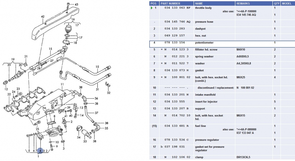
There are several reasons why you might want to remove your AAN intake manifold. In my case, it was to replace the injector inserts, item 12, PN 034133555.
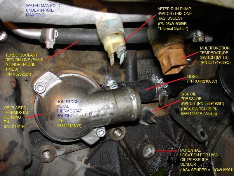
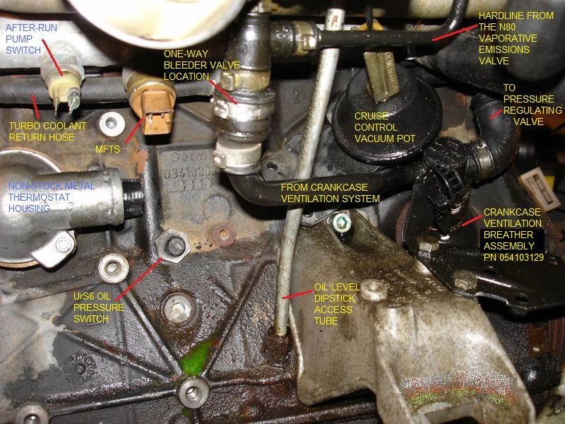
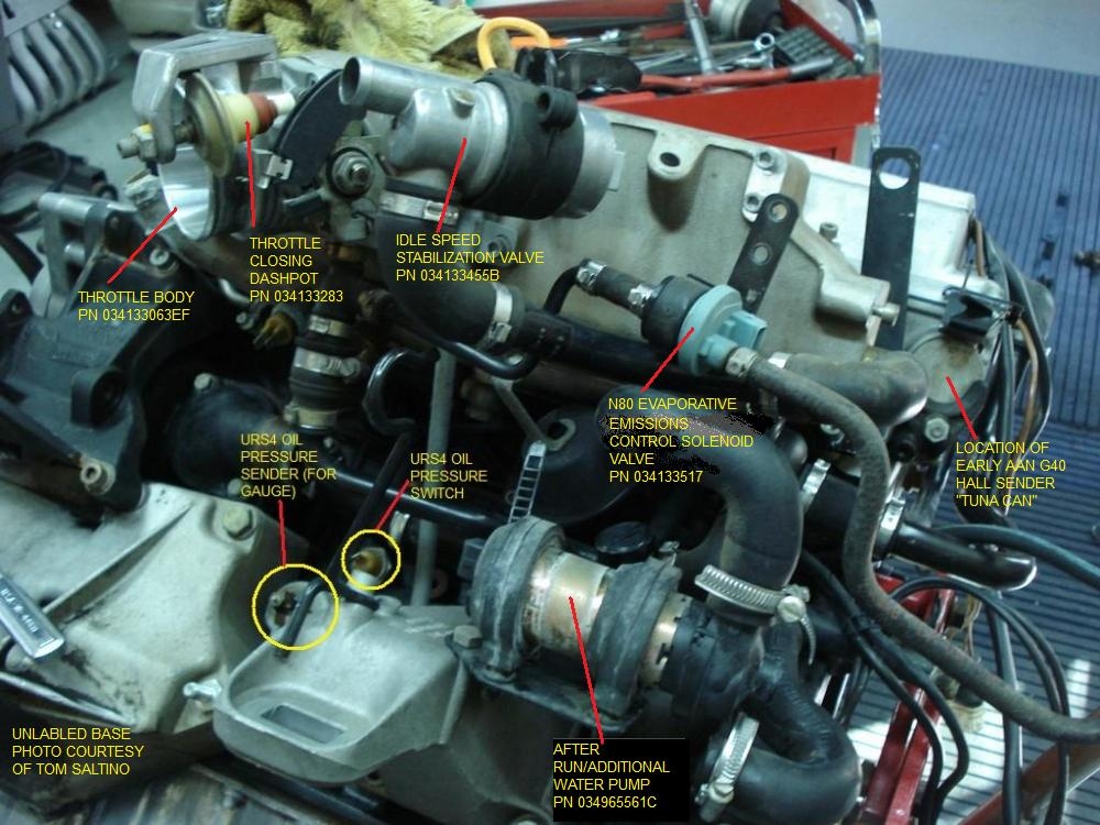
Other examples include better access to some of the hoses or PCV system components under the intake manifold, as shown here:
Before you start, you will need a few things, including the intake manifold gasket (or 034's phenolic spacer and two intake manifold gaskets).
Manifold gasket, Item 22, PN 034129717K:
You will also need a long 6 mm Allen hex tool, preferably one like this factory tool with the ball end (the ball end allows for some slightly off angles, which happens on like 6 out of the 10 bolts):

Photo courtesty of EdiGreg

Photo courtesty of EdiGreg
While you might be able to manouver the fuel rail and injectors out of the intake manifold without disconnecting the fuel rail from the hardlines, doing so would put significant twisting strain on the the flexible lines. Better to remove them at the start of this job. To do so, open the driver's side fuse panel and remove the 20 Amp (yellow) fuse in position 17 (this is the fuel pump fuse). Then start the car, it will start and run briefly until the fuel in the rail is (mostly but not completely) consumed and the pressure has dropped to next to nothing. Now you can disconnect the hoses at the fuel rail. Start with the top one (the feed line) and then go to the bottom one (return). You need a 17 mm wrench to hold on to the fixed portion while turning the moving portion with a 14 mm wrench (flare wrench if you have one). There will be some fuel residual from both pipes so have a catch can underneath the connecttions when you break them.
Now you can remove the 5 mm Allen hex head Item 43 bolts from the top of your Item 42 fuel rail cover. Set the bolts inside the cover and place them together somewhere safe, e.g. the rain tray works for me.
With the cover off, disconnect the two-pin connectors from each of the five injectors and the G40 Cam sensor harness (at the very front of the engine). If you aren't going to move the fuel rail too far, leave the connector harness attached to the fuel rail. If you are goint to move it further, cut the zap-straps at peel the injector/G40 harness off the fuel rail and move it to the top off the cam cover, out of the way.
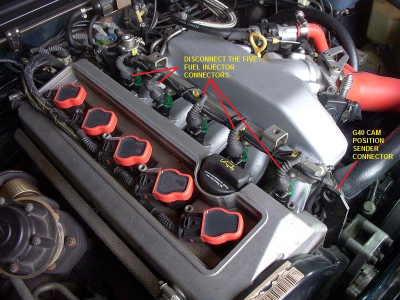
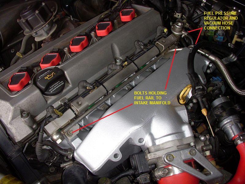
Now remove the two item 27 Allen head bolts (also 5 mm IIRC) that hold the fuel rail to the intake manifold. If you have removed the injector connectors, only one thing is preventing you from lifting the fuel rail and injectors out of and off the intake manifold and that is the vacuum line at the end of the head that is connected to the fuel pressure regulator.
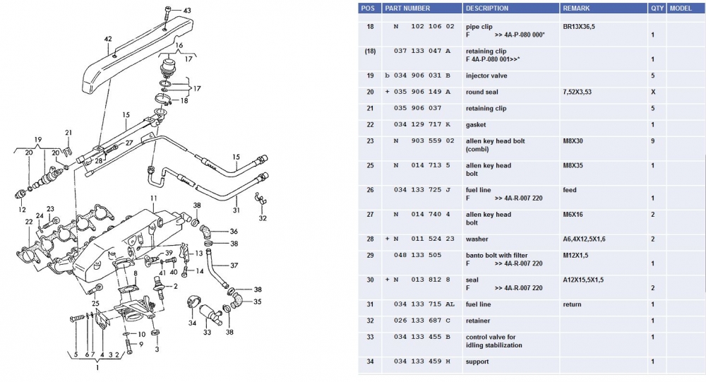
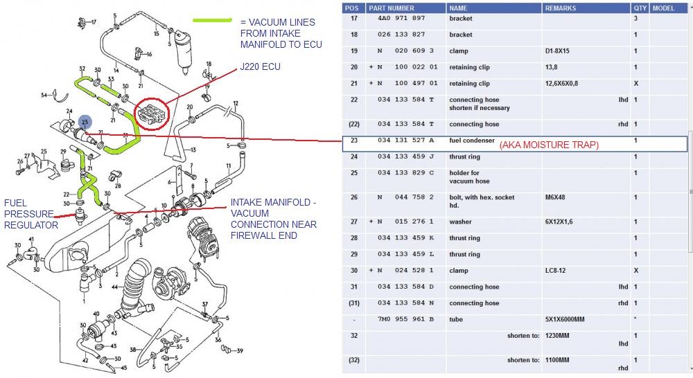
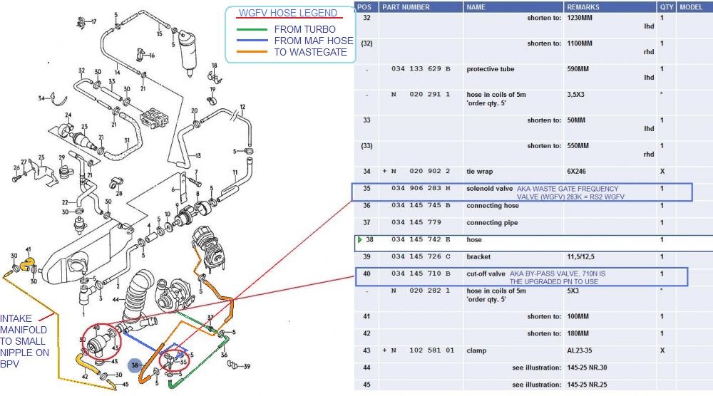
There are actually four vacuum/boost signal lines connected to the intake manifold. Three are at the firewall end of the AAN intake manifold that have to be disconnected: two are connected to brass nipples on the intake manifold and the third is connected to the fuel pressure regulator. Remove the hoses from all three locations at the rear of the intake manifold. The fourth vacuum/boost line is at the front of the intake manifold and is the one that leads to the by-pass valve (Item 41 in the 2nd diagram below). In all cases, once you have the clamps off the hoses, try to get them to twist a bit on the nipple (use pliers as necessary) before you attempt pulling them off. As a last resort, cut them length-wise at the nipple and then either repair (silicon rescue tape) or replace during re-installation.
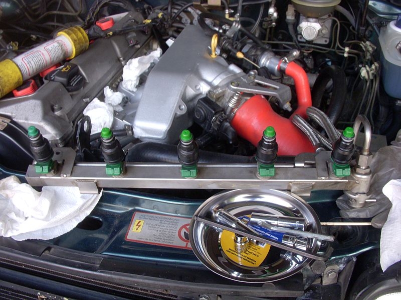
With at least the fuel pressure regulator disconnected, you are now ready to remove the injectors and fuel rail as one unit. Some folks have used a piece of 2 x 4 wood to pry the fuel rail up and out, placing the 2 x 4 under the bottom of the fuel rail and on top of the cam cover and then prying up. I was lucky and didn't need that. I just started and the front and lifted and rocked the fuel injectors and fuel rail up and out with very little drama. (This ease in removal probably reflects the fact that the O-rings on the ends of the injectors had shrunken (the reason I was replacing them and injector inserts was suspected boost leakage there)).
There will still be fuel in the fuel rail so be careful as you lift the rail and hoses up and away from the engine (note that the throttle cable goes over the inlet and return hoses). Drain the hoses into the can you used to catch the fuel when you broke the hose connections.
This photo shows the many things that need to be removed before you can remove the intake manifold.
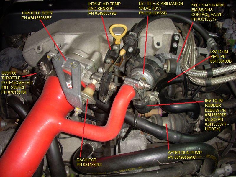
These include:
1. The intercooler to throttle body hose
2. The intercooler to N71 Idle Stabilization hose
3. The N71 to intake manifold hose
4. The throttle cable
5. The cruise control arm from the throttle body
6. The bracket for the N80 Evaporative emissions control valve
7. The ground connections in two locations at the back of the head.
8. The bracket that holds the dipstick in place
9. The one way bleeder valve and PCV system hose on the bottom of the throttle body
10. The rear most engine lift bracket
Items 1 and 2 are obvious and straight forward. When disconnected, twist/shove/cajoal the hose out of the way.
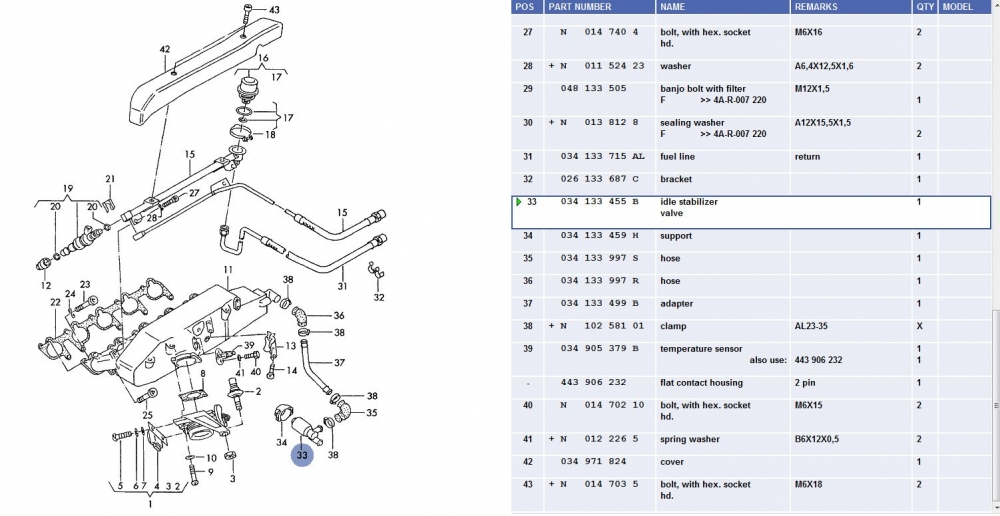
Item 3, the N71 ISV is easy. The ISV to intake manifold hose is connected to a large brass nipple at the back of the intake manifold via an elbow (Item 36 below) and a clamp. Remove the clamp and slide the hose off. Disconnect the ISV 2 pin connector (note the colour of the connecto) and slide the ISV and its Item 34 rubber buffer off the black throttle cable bracket with the pipe and rubber elbow. Set aside.
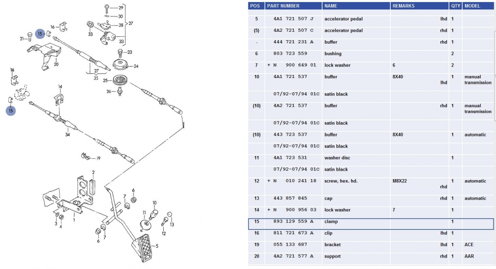
The throttle cable is attached to the intake manifold in two points in addition to be attached to the throttle cam. There is a galvanized steel bracket at the back of the head (note the tang on the bracket and how it fits to the intake manifold notch). There is also the black bracket beside the oil dipstick (also is the N71 bracket). The throttle cable is held into the black bracket by the Item 14 clip (note location and orientation). The cable is held to the throttle cam via the item 15 and 16 clips (pry them off - do NOT lose them!!). Note location and orientation. The photo shows one of the two of the clips on the throttle cam. You will have to twist the throttle cam against the spring to remove the ball end of the throttle cable from the cam. With all the brackets off the intake manifold, move the throttle cable out of the way. Place the brackets, bolts and clips in a safe location.
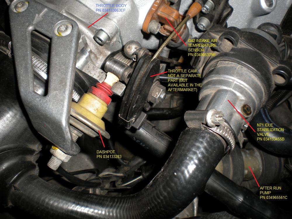
The photo above also shows the socket end of the cruise control actuator rod as it is attached to the ball stud on the throttle cam. You can just see the spring wire clip that holds the socket to the ball. Use a screw driver and/or needle nose pliers to twist the wire clip in a manner that releases the socket from the ball and slide the wire away from the ball (just enough so you can get clearance). Pry the socket off the ball.
The N80 Evaporative Emissions control valve is held to the head via a black painted bracket. Remove the two allen head bolts. The bracket is clearly shown in this photo:
There are two separate sets of brown ground wires at the firewall end of the intake manifold. Remove the bolts that hold them to the manifold. One of them also holds the galvanized steel throttle cable bracket so you might only have one more to do. Note the grouping and number of wires so you can reconnect them later. These are very important grounds and tend to be related to the Motronic ECU, i.e. no grounds, no go.
There is one bolt that holds the oil dipstick guide tube to the intake manifold. Remove the bolt and set aside. Swing the tube away from the "porthole" in the intake manifold (that provides access to one of the bottom bolts holding the the intake manifold to the head).
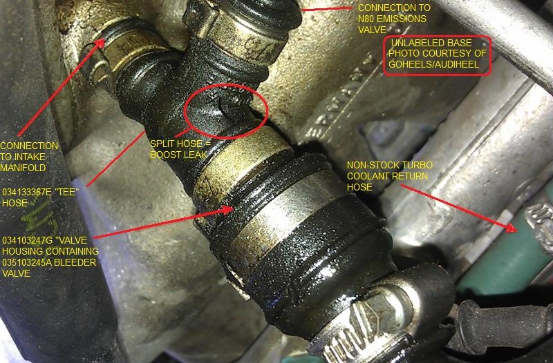
The one-way bleeder valve is in a hose that is connected to a nipple at the bottom of the intake manifold just under the throttle body. Mine still had the Oetiker clamp so I just opened the loop with an awl (you could use a screw driver) and slip the hose down off the nipple. (I use pinch pliers to retighten the loop). Here is a photo that shows this connection:
The rear-most engine lift bracket is held to the head by two bolts, both 6 mm allen heads, one is longer than the other. Note the location of each. (This is your first opporunity to use the long 6 mm ball end allen socket).
So with all of those items off the intake manifold, you are ready to finally remove the intake manifold. At this point there are 9 6 mm Allen bolts still to be removed. Four of these are accessed through the tubes (ports) through the intake manifold, five from above. The top five are easy. Of the four bolts accessed through the tubes, at least one (on cylinder 2 (second from the front) is captured by the intake runner and cannot be removed fully until you pull the intake manifold off. So remove the bolts and place in a safe location. Lift the intake away from the head, try not to drop any captured bolts. Set aside.
At this point, you will be looking at something like this:
Now, why did I do this again? Because I thought that I had some boost leakage at the injector inserts and I wanted to eliminate that possibility. Against some recommentations, I attempted to remove the inserts from the intake manifold with the manifold still on the head, with only the fuel rail removed. Three of the inserts came out fine (with a 10 mm Allen socket stuffed down their throats). *HOWEVER*, two of them jammed coming out and the 10 mm allen spun in the old and brittle plastic. This meant that there were probably chunks of plastic laying in the intake ports or perhaps by the valves. This meant I HAD TO remove the intake manifold. When I got the manifold off, this was what I found in those two cylinders (1 and 5 as it happens):

I used my shop vac with a nozzle that I made previously to clean out the spark plug wells using an 8" lenght of Pex plastic 1/2" water pipe to vacuum out all then intake valve ports. Then I swabbed them out and then re-vacuumed and re-inspected. Seemed clean.
On to the original goal, replacing the injector inserts:
The remaining two inserts had to be cut out because they were jammed (one of them had damaged threads at the top due to the actions of "professional" mechanics (probably a shop flunky)).
With the inserts out and the threads cleaned (and fixed in my case), you can then proceed with installation of the new inserts.
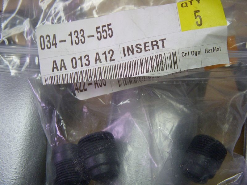
I bought 5 each from two different suppliers in case there were issues. (There weren't). The PN is 034133555:
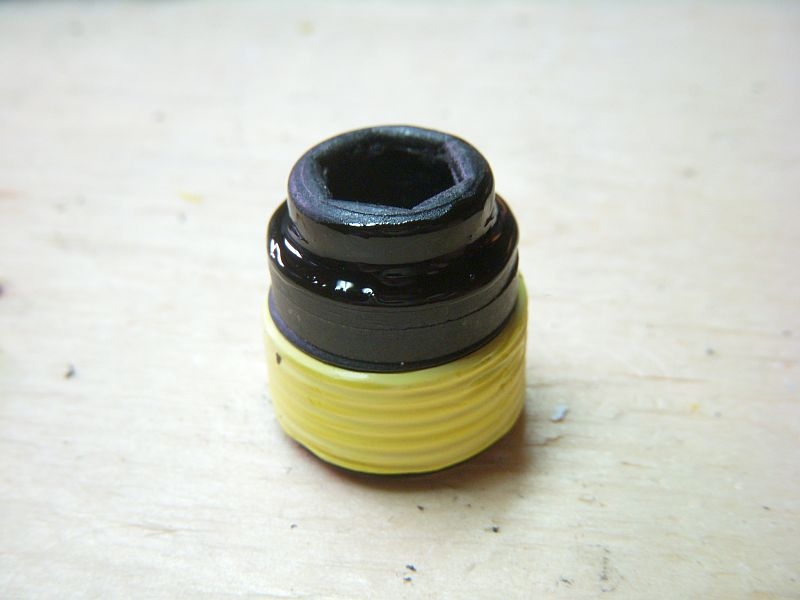
After asking the forum for advice on sealing these inserts into the intake manifold, I decided to use yellow PFTE gas-fitter's tape on the thread and aviation sealant on the nose of the insert and the inner edge of the intake manifold.

I wrapped the injector inserts in two layers of the yellow tape, in a direction such that as the injector is screwed into the manifold in a clockwise direction, the "tail" of the tape is draggged around, not bunched up.
I then used the Q-tip to coat the shoulder of the "nose" of the injector insert with the aviation sealant. The result was this:
A small amount of aviation sealant was then applied to the injector insert seat in the intake manifold:
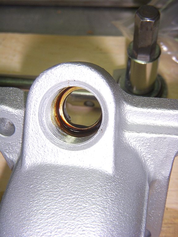
At that point, the injector insert was hand threaded into its seat in the intake manifold and then snugged with a 10 mm Allen socket. I checked to see if there was at least some sealant around the edge of the nose of the injector insert and if I didn't like it, I remove the insert and started the process over. This is what I was looking for:

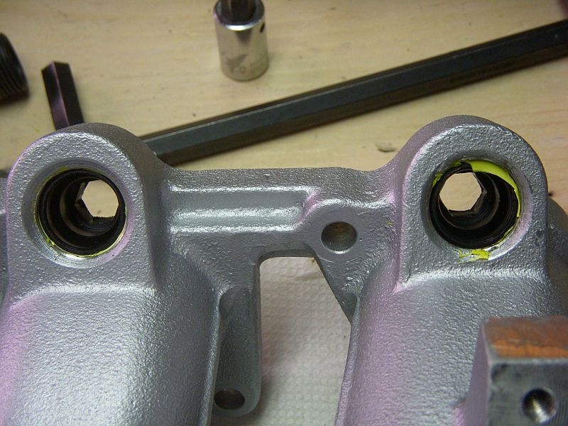
On the top side, I trimmed any stray teflon tape (just for neatness). The one on the left has been trimmed, the one on the right is about to be trimmed:
With all of the five new injector inserts installed in the cleaned (and painted) intake manifold, I was ready to re-install everything.
To quote the Bentley "Installation is the reverse of removal".
This is generally true.
Here are a couple of hints:
1. After cleaning the gasket surface of the head in preparation for the new intake manifold gasket, I used two short 1/4" wooden dowels in the upper holes of No.1 and No.5 to act as guides for the intake manifold and to hold the new gasket in place.
2. I put all four of "hidden" lower intake manifold bolts (the ones accessed through the tubes) into there respective holes in the intake manifold before I moved the intake manifold to the head. One (No.2, lower) would have to be done that way for sure but I got lucky at it worked out for all 4 of the hidden ones.
3. When installing the cleaned, refurbed and re-O-ringed injectors into the fuel rail, I used a tiny amount of Vaseline on the O-rings. Then I pressed the injector into the fuel rail and secured it with an injector clip (it is a little tricky to get the clip on in the correct location so it is in a groove in the injector and over the fuel rail fitting).
4. With the injectors in the fuel rail, I then applied a light dab of Vaseline to each of the new O-rings on the discharge end of the injector.
5. Installing the fuel rail and injectors back into their new seats is easy. Just go slow. Get all the injectors at the outer edge of the injector insert before you apply gentle but firm pressure to push the injectors fully into their respective seats. You don't have them all the way in unless the distance between the top of the fuel rail tap and intake manifold is vertually nothing.
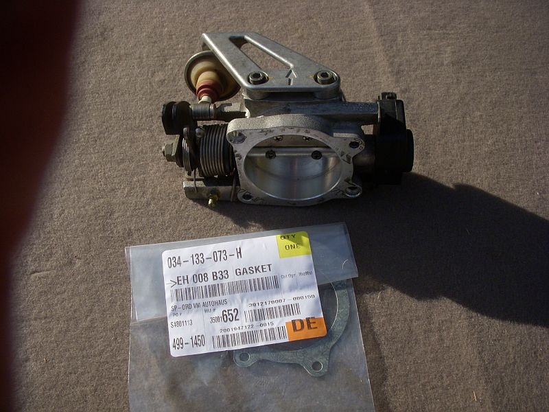
6. If you removed the throttle body for any reason, you will need a new gasket PN 034133073H. While I didn't remove the dashpot and bracket when I removed the throttle body, it is easier to reinstall the throttle body if you remove the dashpot and bracket first, then install the throttle body and then re-install the dashpot and bracket.
Hope that wasn't too boring and that it helps somebody in the future.
There are several reasons why you might want to remove your AAN intake manifold. In my case, it was to replace the injector inserts, item 12, PN 034133555.
Other examples include better access to some of the hoses or PCV system components under the intake manifold, as shown here:
Before you start, you will need a few things, including the intake manifold gasket (or 034's phenolic spacer and two intake manifold gaskets).
Manifold gasket, Item 22, PN 034129717K:
You will also need a long 6 mm Allen hex tool, preferably one like this factory tool with the ball end (the ball end allows for some slightly off angles, which happens on like 6 out of the 10 bolts):
Photo courtesty of EdiGreg
Photo courtesty of EdiGreg
While you might be able to manouver the fuel rail and injectors out of the intake manifold without disconnecting the fuel rail from the hardlines, doing so would put significant twisting strain on the the flexible lines. Better to remove them at the start of this job. To do so, open the driver's side fuse panel and remove the 20 Amp (yellow) fuse in position 17 (this is the fuel pump fuse). Then start the car, it will start and run briefly until the fuel in the rail is (mostly but not completely) consumed and the pressure has dropped to next to nothing. Now you can disconnect the hoses at the fuel rail. Start with the top one (the feed line) and then go to the bottom one (return). You need a 17 mm wrench to hold on to the fixed portion while turning the moving portion with a 14 mm wrench (flare wrench if you have one). There will be some fuel residual from both pipes so have a catch can underneath the connecttions when you break them.
Now you can remove the 5 mm Allen hex head Item 43 bolts from the top of your Item 42 fuel rail cover. Set the bolts inside the cover and place them together somewhere safe, e.g. the rain tray works for me.
With the cover off, disconnect the two-pin connectors from each of the five injectors and the G40 Cam sensor harness (at the very front of the engine). If you aren't going to move the fuel rail too far, leave the connector harness attached to the fuel rail. If you are goint to move it further, cut the zap-straps at peel the injector/G40 harness off the fuel rail and move it to the top off the cam cover, out of the way.
Now remove the two item 27 Allen head bolts (also 5 mm IIRC) that hold the fuel rail to the intake manifold. If you have removed the injector connectors, only one thing is preventing you from lifting the fuel rail and injectors out of and off the intake manifold and that is the vacuum line at the end of the head that is connected to the fuel pressure regulator.
There are actually four vacuum/boost signal lines connected to the intake manifold. Three are at the firewall end of the AAN intake manifold that have to be disconnected: two are connected to brass nipples on the intake manifold and the third is connected to the fuel pressure regulator. Remove the hoses from all three locations at the rear of the intake manifold. The fourth vacuum/boost line is at the front of the intake manifold and is the one that leads to the by-pass valve (Item 41 in the 2nd diagram below). In all cases, once you have the clamps off the hoses, try to get them to twist a bit on the nipple (use pliers as necessary) before you attempt pulling them off. As a last resort, cut them length-wise at the nipple and then either repair (silicon rescue tape) or replace during re-installation.
With at least the fuel pressure regulator disconnected, you are now ready to remove the injectors and fuel rail as one unit. Some folks have used a piece of 2 x 4 wood to pry the fuel rail up and out, placing the 2 x 4 under the bottom of the fuel rail and on top of the cam cover and then prying up. I was lucky and didn't need that. I just started and the front and lifted and rocked the fuel injectors and fuel rail up and out with very little drama. (This ease in removal probably reflects the fact that the O-rings on the ends of the injectors had shrunken (the reason I was replacing them and injector inserts was suspected boost leakage there)).
There will still be fuel in the fuel rail so be careful as you lift the rail and hoses up and away from the engine (note that the throttle cable goes over the inlet and return hoses). Drain the hoses into the can you used to catch the fuel when you broke the hose connections.
This photo shows the many things that need to be removed before you can remove the intake manifold.
These include:
1. The intercooler to throttle body hose
2. The intercooler to N71 Idle Stabilization hose
3. The N71 to intake manifold hose
4. The throttle cable
5. The cruise control arm from the throttle body
6. The bracket for the N80 Evaporative emissions control valve
7. The ground connections in two locations at the back of the head.
8. The bracket that holds the dipstick in place
9. The one way bleeder valve and PCV system hose on the bottom of the throttle body
10. The rear most engine lift bracket
Items 1 and 2 are obvious and straight forward. When disconnected, twist/shove/cajoal the hose out of the way.
Item 3, the N71 ISV is easy. The ISV to intake manifold hose is connected to a large brass nipple at the back of the intake manifold via an elbow (Item 36 below) and a clamp. Remove the clamp and slide the hose off. Disconnect the ISV 2 pin connector (note the colour of the connecto) and slide the ISV and its Item 34 rubber buffer off the black throttle cable bracket with the pipe and rubber elbow. Set aside.
The throttle cable is attached to the intake manifold in two points in addition to be attached to the throttle cam. There is a galvanized steel bracket at the back of the head (note the tang on the bracket and how it fits to the intake manifold notch). There is also the black bracket beside the oil dipstick (also is the N71 bracket). The throttle cable is held into the black bracket by the Item 14 clip (note location and orientation). The cable is held to the throttle cam via the item 15 and 16 clips (pry them off - do NOT lose them!!). Note location and orientation. The photo shows one of the two of the clips on the throttle cam. You will have to twist the throttle cam against the spring to remove the ball end of the throttle cable from the cam. With all the brackets off the intake manifold, move the throttle cable out of the way. Place the brackets, bolts and clips in a safe location.
The photo above also shows the socket end of the cruise control actuator rod as it is attached to the ball stud on the throttle cam. You can just see the spring wire clip that holds the socket to the ball. Use a screw driver and/or needle nose pliers to twist the wire clip in a manner that releases the socket from the ball and slide the wire away from the ball (just enough so you can get clearance). Pry the socket off the ball.
The N80 Evaporative Emissions control valve is held to the head via a black painted bracket. Remove the two allen head bolts. The bracket is clearly shown in this photo:
There are two separate sets of brown ground wires at the firewall end of the intake manifold. Remove the bolts that hold them to the manifold. One of them also holds the galvanized steel throttle cable bracket so you might only have one more to do. Note the grouping and number of wires so you can reconnect them later. These are very important grounds and tend to be related to the Motronic ECU, i.e. no grounds, no go.
There is one bolt that holds the oil dipstick guide tube to the intake manifold. Remove the bolt and set aside. Swing the tube away from the "porthole" in the intake manifold (that provides access to one of the bottom bolts holding the the intake manifold to the head).
The one-way bleeder valve is in a hose that is connected to a nipple at the bottom of the intake manifold just under the throttle body. Mine still had the Oetiker clamp so I just opened the loop with an awl (you could use a screw driver) and slip the hose down off the nipple. (I use pinch pliers to retighten the loop). Here is a photo that shows this connection:
The rear-most engine lift bracket is held to the head by two bolts, both 6 mm allen heads, one is longer than the other. Note the location of each. (This is your first opporunity to use the long 6 mm ball end allen socket).
So with all of those items off the intake manifold, you are ready to finally remove the intake manifold. At this point there are 9 6 mm Allen bolts still to be removed. Four of these are accessed through the tubes (ports) through the intake manifold, five from above. The top five are easy. Of the four bolts accessed through the tubes, at least one (on cylinder 2 (second from the front) is captured by the intake runner and cannot be removed fully until you pull the intake manifold off. So remove the bolts and place in a safe location. Lift the intake away from the head, try not to drop any captured bolts. Set aside.
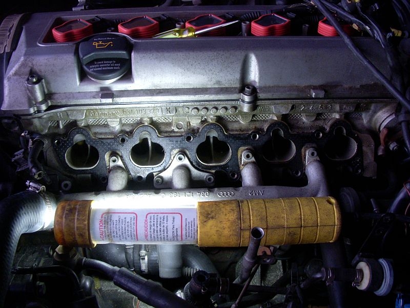
At this point, you will be looking at something like this:
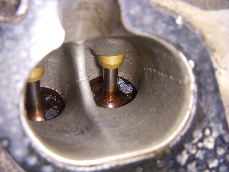
Now, why did I do this again? Because I thought that I had some boost leakage at the injector inserts and I wanted to eliminate that possibility. Against some recommentations, I attempted to remove the inserts from the intake manifold with the manifold still on the head, with only the fuel rail removed. Three of the inserts came out fine (with a 10 mm Allen socket stuffed down their throats). *HOWEVER*, two of them jammed coming out and the 10 mm allen spun in the old and brittle plastic. This meant that there were probably chunks of plastic laying in the intake ports or perhaps by the valves. This meant I HAD TO remove the intake manifold. When I got the manifold off, this was what I found in those two cylinders (1 and 5 as it happens):
I used my shop vac with a nozzle that I made previously to clean out the spark plug wells using an 8" lenght of Pex plastic 1/2" water pipe to vacuum out all then intake valve ports. Then I swabbed them out and then re-vacuumed and re-inspected. Seemed clean.
On to the original goal, replacing the injector inserts:
The remaining two inserts had to be cut out because they were jammed (one of them had damaged threads at the top due to the actions of "professional" mechanics (probably a shop flunky)).
With the inserts out and the threads cleaned (and fixed in my case), you can then proceed with installation of the new inserts.
I bought 5 each from two different suppliers in case there were issues. (There weren't). The PN is 034133555:
After asking the forum for advice on sealing these inserts into the intake manifold, I decided to use yellow PFTE gas-fitter's tape on the thread and aviation sealant on the nose of the insert and the inner edge of the intake manifold.
I wrapped the injector inserts in two layers of the yellow tape, in a direction such that as the injector is screwed into the manifold in a clockwise direction, the "tail" of the tape is draggged around, not bunched up.
I then used the Q-tip to coat the shoulder of the "nose" of the injector insert with the aviation sealant. The result was this:
A small amount of aviation sealant was then applied to the injector insert seat in the intake manifold:
At that point, the injector insert was hand threaded into its seat in the intake manifold and then snugged with a 10 mm Allen socket. I checked to see if there was at least some sealant around the edge of the nose of the injector insert and if I didn't like it, I remove the insert and started the process over. This is what I was looking for:
On the top side, I trimmed any stray teflon tape (just for neatness). The one on the left has been trimmed, the one on the right is about to be trimmed:
With all of the five new injector inserts installed in the cleaned (and painted) intake manifold, I was ready to re-install everything.
To quote the Bentley "Installation is the reverse of removal".
This is generally true.
Here are a couple of hints:
1. After cleaning the gasket surface of the head in preparation for the new intake manifold gasket, I used two short 1/4" wooden dowels in the upper holes of No.1 and No.5 to act as guides for the intake manifold and to hold the new gasket in place.
2. I put all four of "hidden" lower intake manifold bolts (the ones accessed through the tubes) into there respective holes in the intake manifold before I moved the intake manifold to the head. One (No.2, lower) would have to be done that way for sure but I got lucky at it worked out for all 4 of the hidden ones.
3. When installing the cleaned, refurbed and re-O-ringed injectors into the fuel rail, I used a tiny amount of Vaseline on the O-rings. Then I pressed the injector into the fuel rail and secured it with an injector clip (it is a little tricky to get the clip on in the correct location so it is in a groove in the injector and over the fuel rail fitting).
4. With the injectors in the fuel rail, I then applied a light dab of Vaseline to each of the new O-rings on the discharge end of the injector.
5. Installing the fuel rail and injectors back into their new seats is easy. Just go slow. Get all the injectors at the outer edge of the injector insert before you apply gentle but firm pressure to push the injectors fully into their respective seats. You don't have them all the way in unless the distance between the top of the fuel rail tap and intake manifold is vertually nothing.
6. If you removed the throttle body for any reason, you will need a new gasket PN 034133073H. While I didn't remove the dashpot and bracket when I removed the throttle body, it is easier to reinstall the throttle body if you remove the dashpot and bracket first, then install the throttle body and then re-install the dashpot and bracket.
Hope that wasn't too boring and that it helps somebody in the future.


Thread
Thread Starter
Forum
Replies
Last Post
ECS Tuning-Audi
A4 (B8 Platform) Discussion
21
09-11-2021 04:04 PM
wjhpilot
S4 (B8 Platform) Discussion
0
09-04-2015 01:43 PM
Powerofbabel
Parts For Sale - Archive (NO NEW POSTS HERE)
0
09-02-2015 10:08 AM
ECS Tuning-Audi
A4 (B7 Platform) Discussion
0
09-01-2015 09:16 AM
ECS Tuning-Audi
Audi A5 / S5 / RS5 Coupe & Cabrio (B8)
0
09-01-2015 08:27 AM