CAR UPDATE: Rear sub-frame modifications...
 06-23-2009, 07:09 PM
#1
AudiWorld Super User
Thread Starter

Join Date: Nov 2002
Location: Montreal, Canada
Posts: 18,597
Likes: 0
Received 0 Likes
on
0 Posts
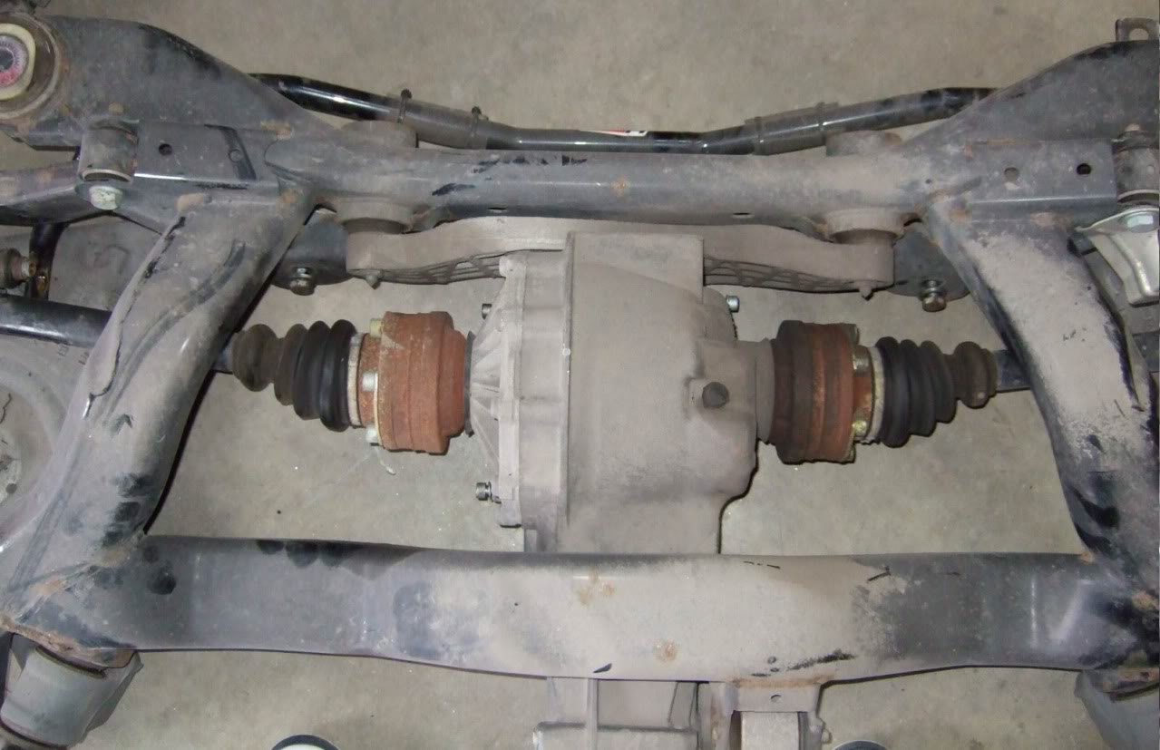
We took the rear sub-frame out complete with the rear diff.
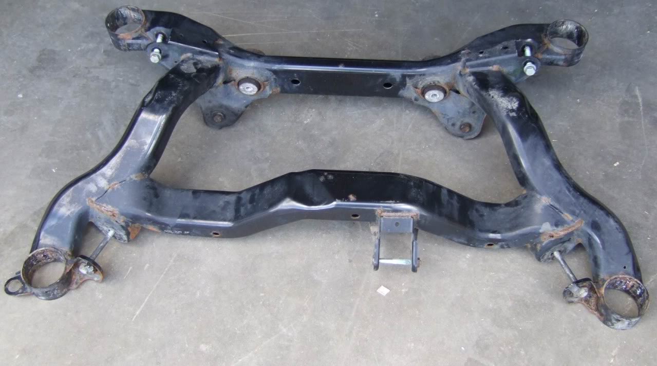
Rear sub-frame completely stripped.
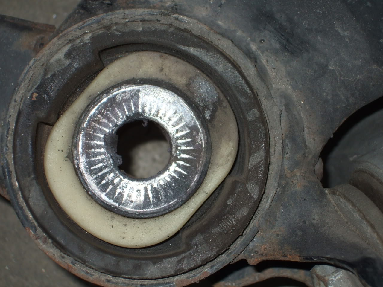
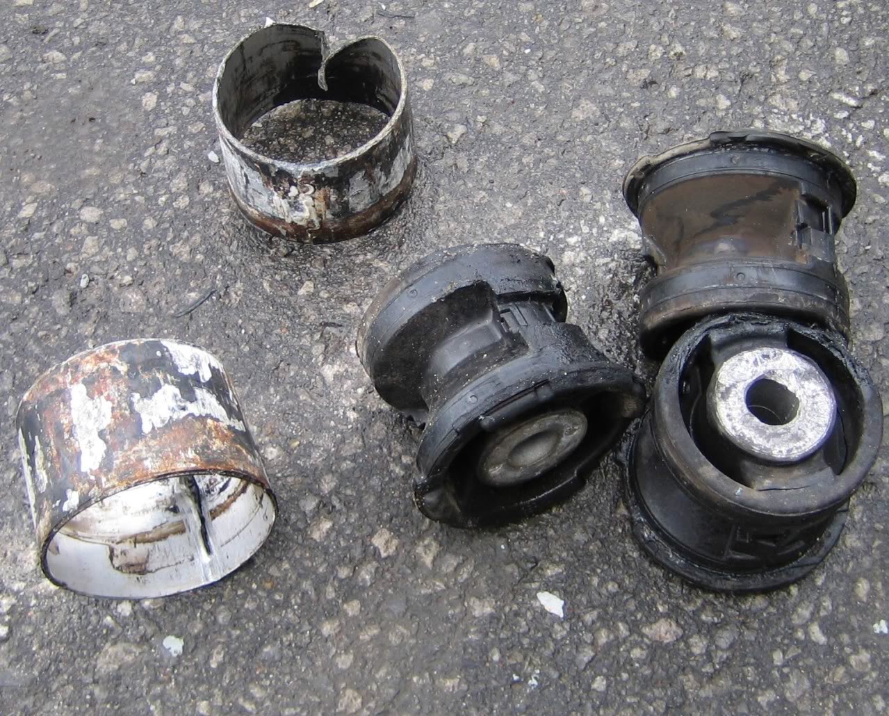
The main reason behind this mod was to remove the rubber bushing from the sub-frame to get the mushy rubber feel out of the car. Here we have one of four attachment points with one of those rubber bushings. They are filled withy some kind of oil too so removing them can get messy.
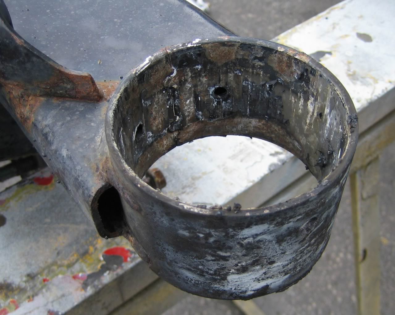
The attachment point once the rubber bushing is removed.
The rubber bushings after removal.
Now the actual mod can start. First we bought tubing to shape it into some parts to make up the new solid mounts.
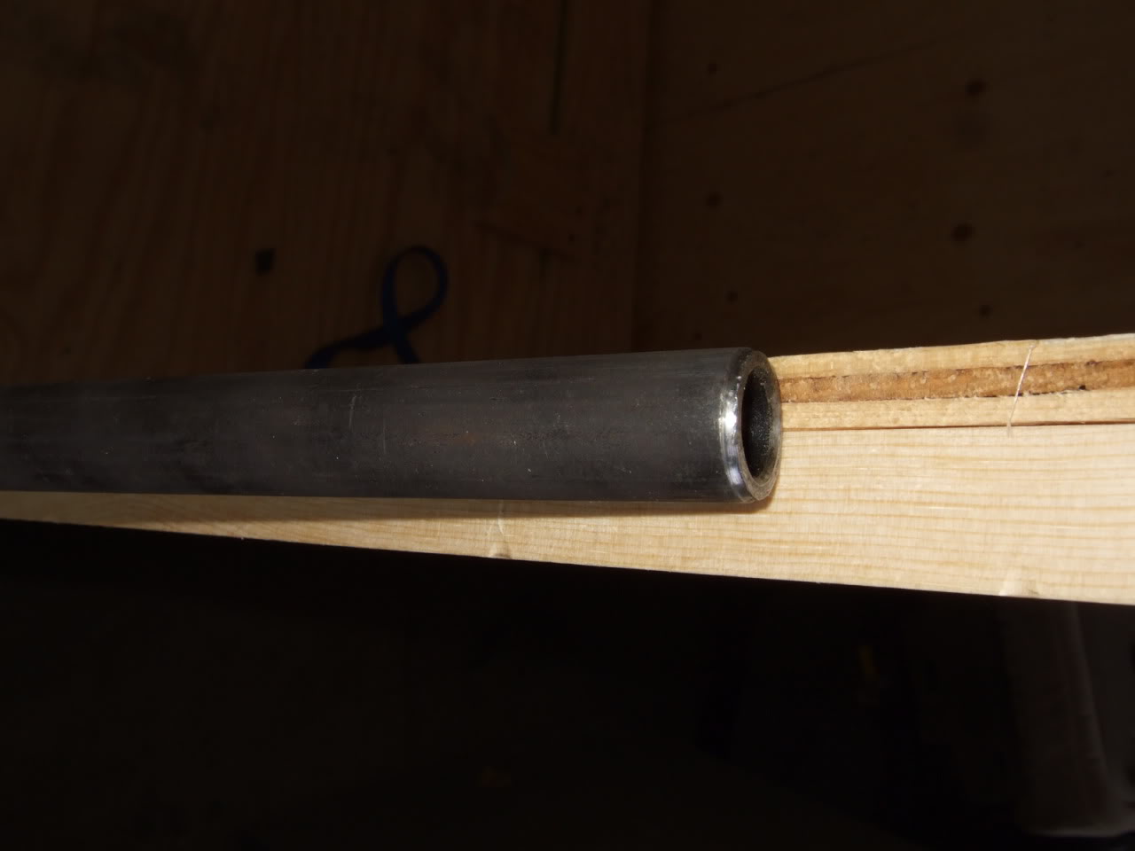
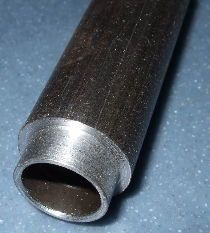
Here�s what the tubing looks like after the machining.
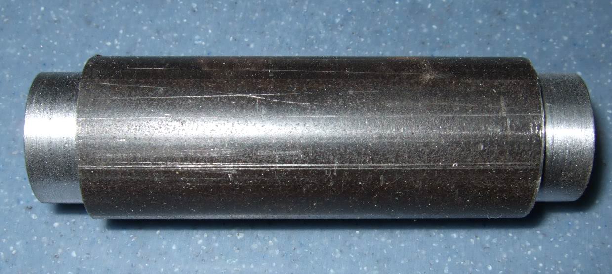
Here�s another angle.
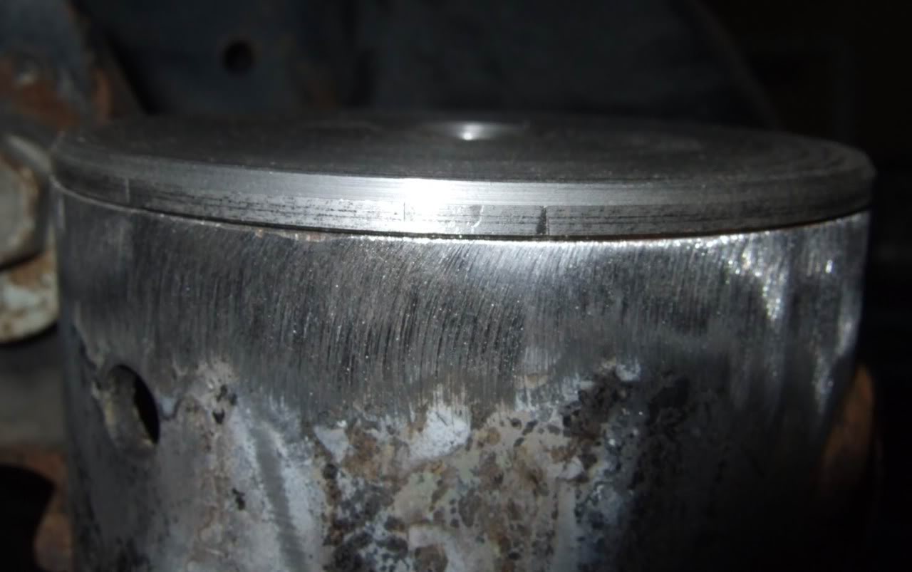
Then we got a big steel bar (3.5� across) to make 8 new �pucks� to replace the rubber bushings with these.
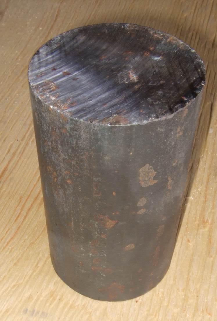
The steel bar was machined down to this. They are about 3/16 thick.
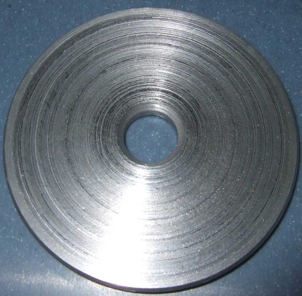
They are also machined with a bevelled centre.
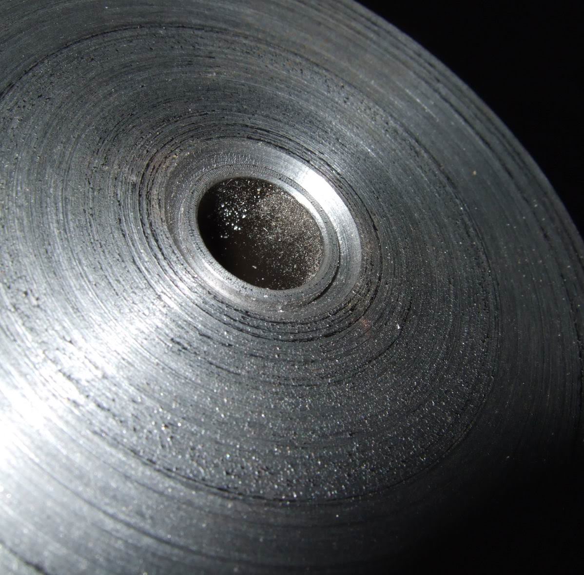
This is how they fit together. The hollow tubing is welded at each end and serves as a guide for the bolt/stud. You can also see that the underneath of the edge on the puck is also bevelled.
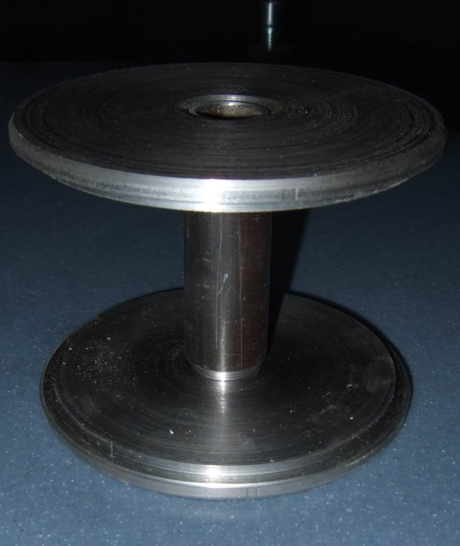
The outer edge is bevelled so as to make a nice tight fit onto the sub-frame.
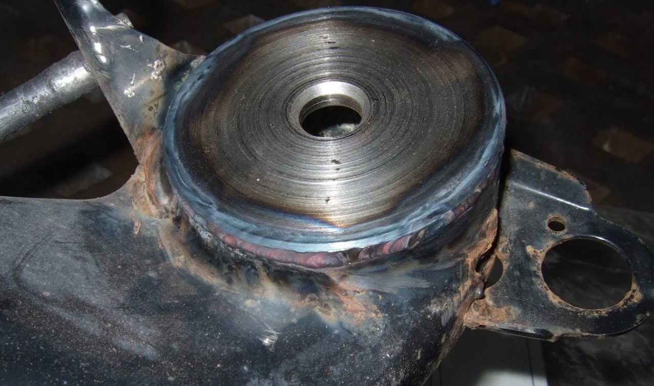
Then the pucks are welded in place onto the sub-frame.
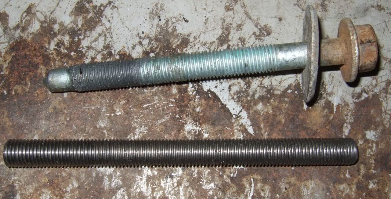
The original OEM bolt and the replacement stud we decided to use to secure the sub-frame to the chassis.
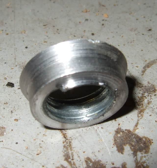
Because the bolt going through the new puck design was sort of loose we felt it was necessary to make a conic shaped spacer that would fit into the bevelled portion of the puck to keep everything sturdy with no play.
This is how it fits onto the stud.
While the sub-frame was off the car we took the time to repair a broken �toe adjustment�.
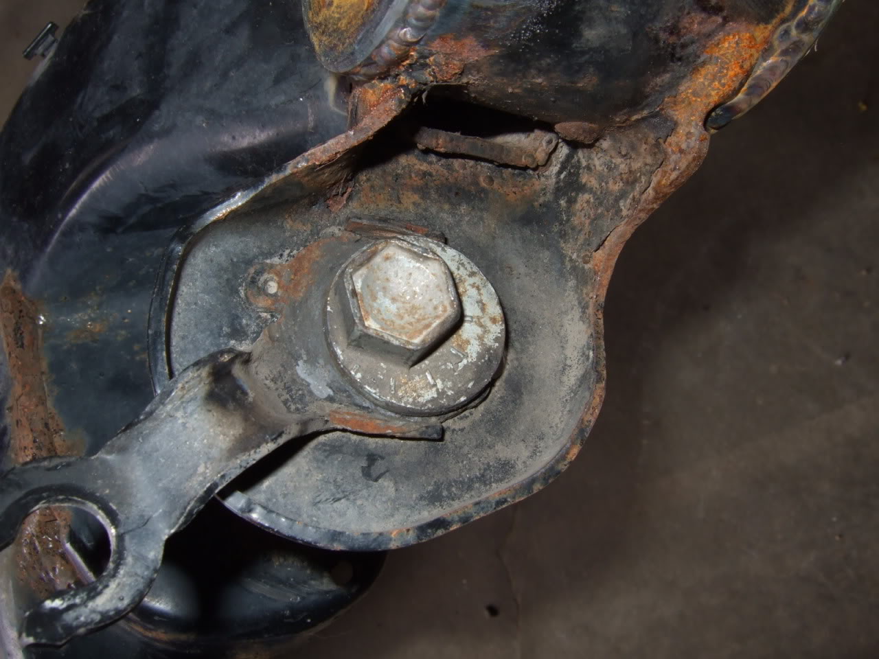
This is how it should look like when there is no damage. Two small edges on either side of the cam bolt.
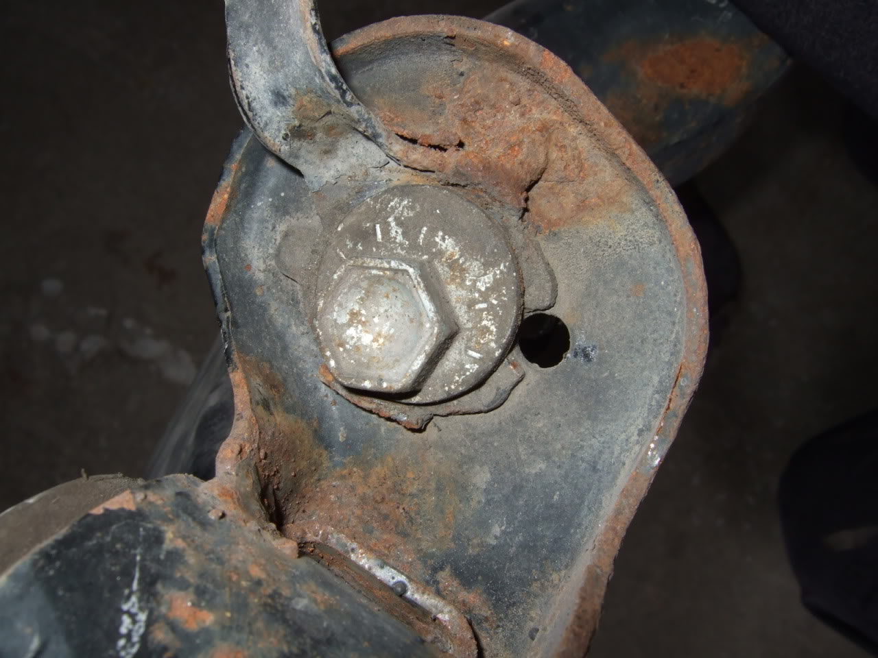
Here the one that�s damaged (by some mechanic with and over zealous torque gun). On one side it is completely gone and so the cam bolt had no effect on the toe adjustment. We tried to fix it last year by welding a strip which helped out but was far from being great.
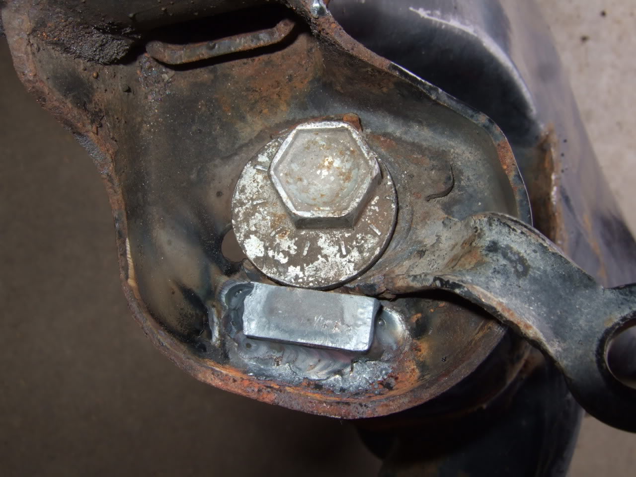
Now the proper repair. This should solve my problem.
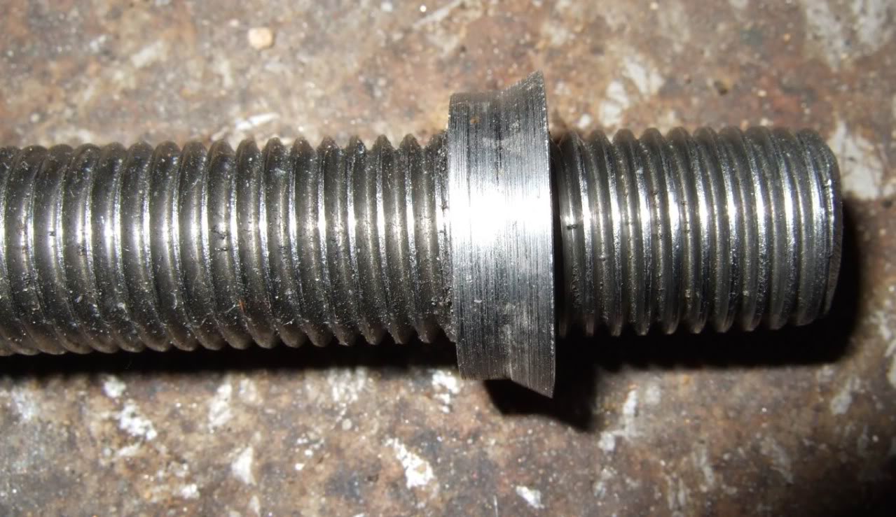
This is how the stud fits through the new solid mount and through the pucks. You can see the conical shaped spacer that centres and keeps the stud steady. Blue Loctite was used to secure the spacer in its proper place on the stud.
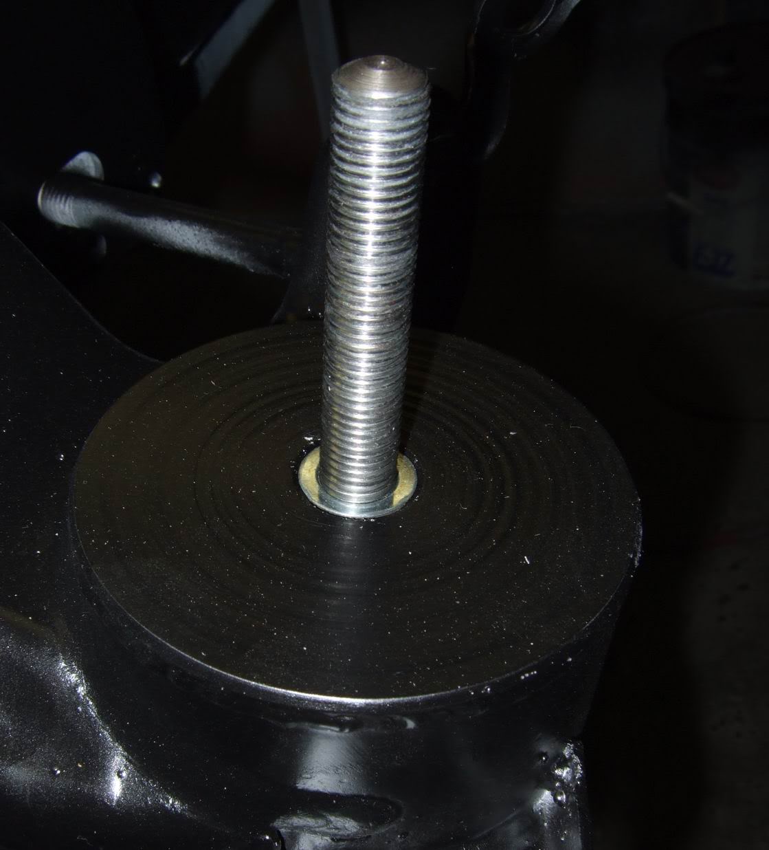
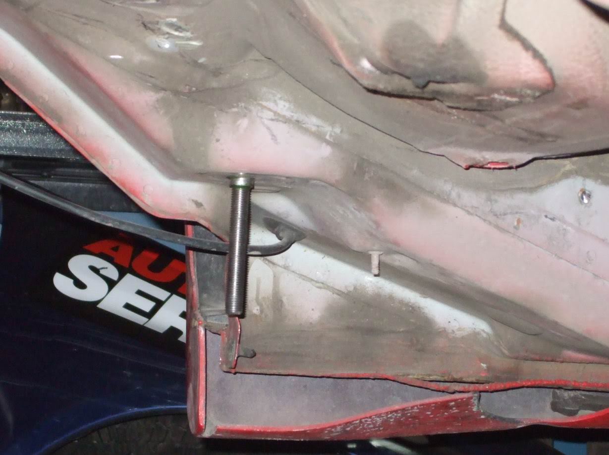
Once the Loctite had done its job by securing the spacer, I went on to install the 4 studs onto the chassis. Loctite was also used to secure the studs to the chassis.
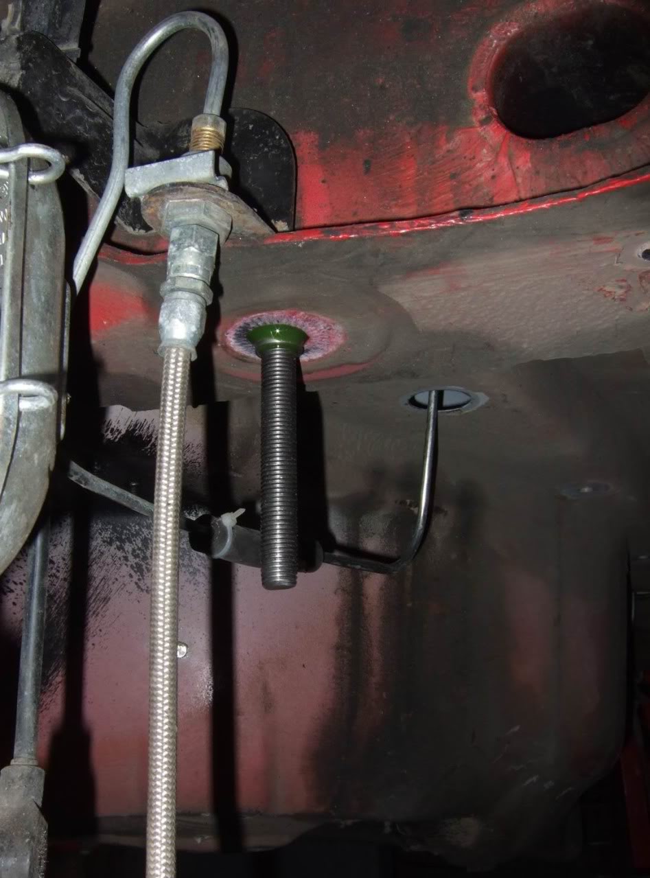
Another stud.
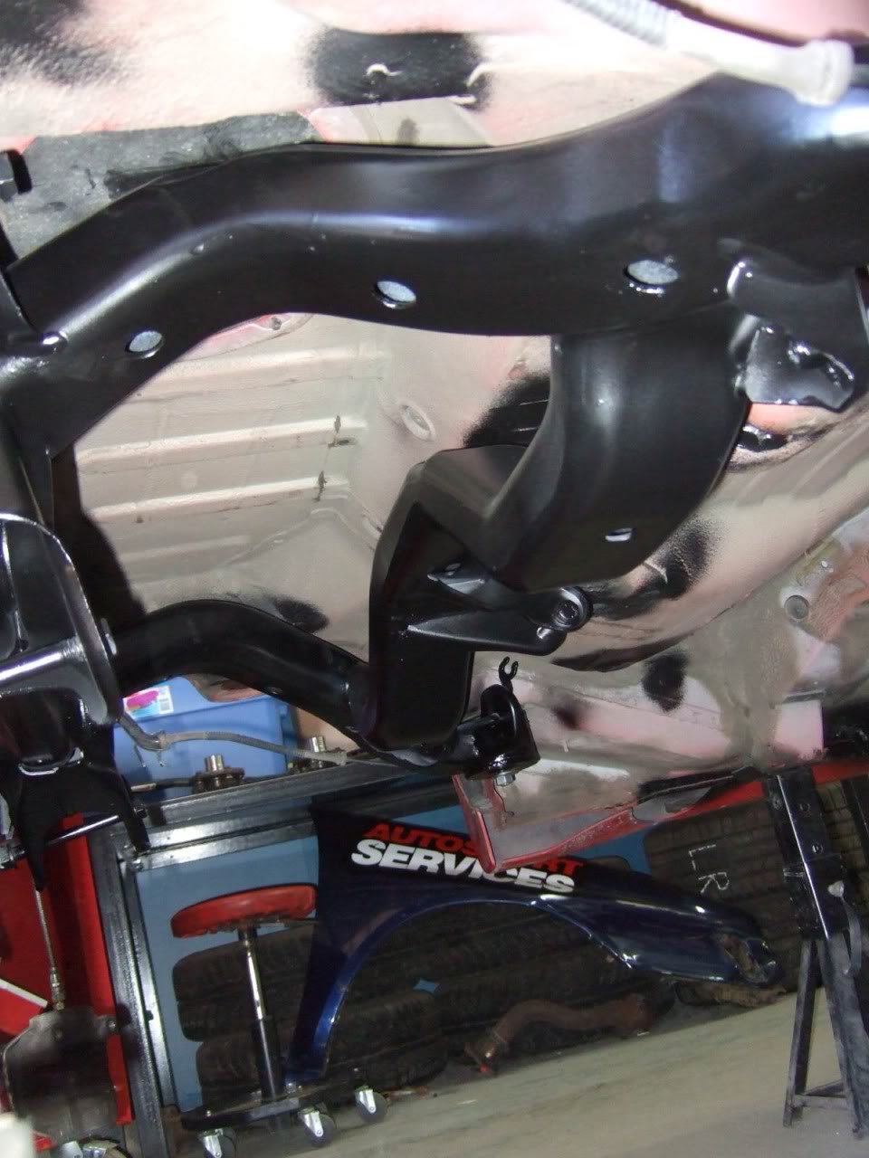
As you probably noticed in the initial pictures the sub-frame was pretty rusted especially in the welds. So I sand blasted all the critical areas affected by the rust, applied a thick coat of filler primer and then two or three coats of black paint just to protect and keep the sub-frame clean.
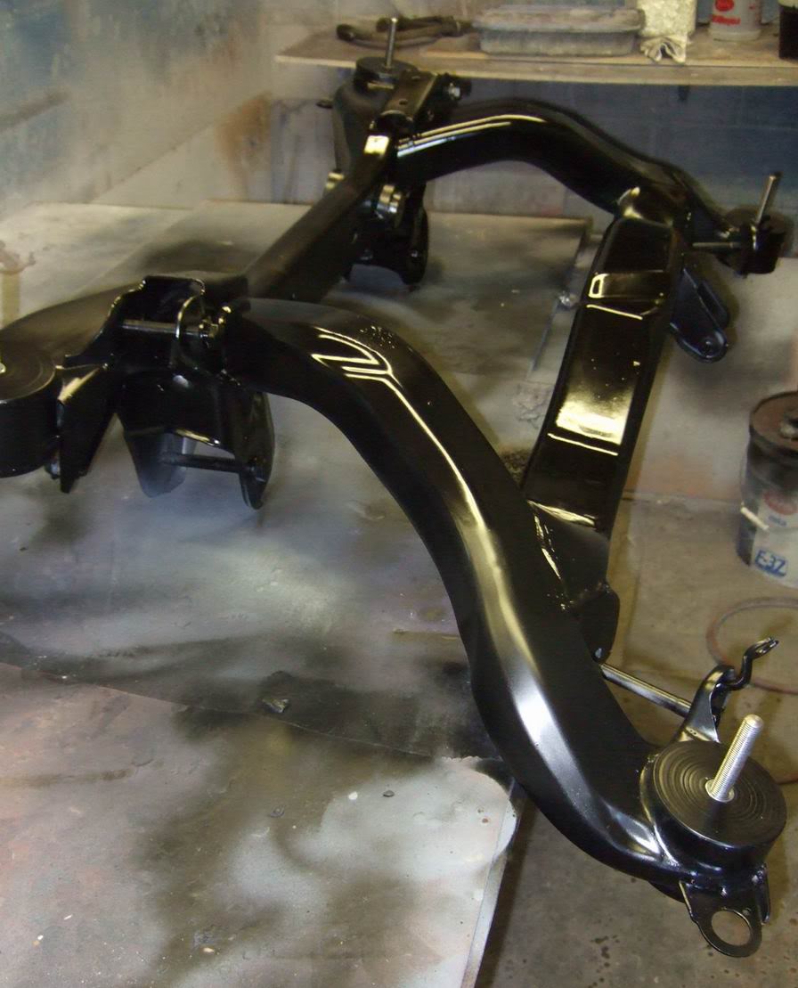
Then we went ahead and installed the sub-frame back onto the car. The suspension, rear diff and other parts will go on soon.
Rear sub-frame completely stripped.
The main reason behind this mod was to remove the rubber bushing from the sub-frame to get the mushy rubber feel out of the car. Here we have one of four attachment points with one of those rubber bushings. They are filled withy some kind of oil too so removing them can get messy.
The attachment point once the rubber bushing is removed.
The rubber bushings after removal.
Now the actual mod can start. First we bought tubing to shape it into some parts to make up the new solid mounts.
Here�s what the tubing looks like after the machining.
Here�s another angle.
Then we got a big steel bar (3.5� across) to make 8 new �pucks� to replace the rubber bushings with these.
The steel bar was machined down to this. They are about 3/16 thick.
They are also machined with a bevelled centre.
This is how they fit together. The hollow tubing is welded at each end and serves as a guide for the bolt/stud. You can also see that the underneath of the edge on the puck is also bevelled.
The outer edge is bevelled so as to make a nice tight fit onto the sub-frame.
Then the pucks are welded in place onto the sub-frame.
The original OEM bolt and the replacement stud we decided to use to secure the sub-frame to the chassis.
Because the bolt going through the new puck design was sort of loose we felt it was necessary to make a conic shaped spacer that would fit into the bevelled portion of the puck to keep everything sturdy with no play.
This is how it fits onto the stud.
While the sub-frame was off the car we took the time to repair a broken �toe adjustment�.
This is how it should look like when there is no damage. Two small edges on either side of the cam bolt.
Here the one that�s damaged (by some mechanic with and over zealous torque gun). On one side it is completely gone and so the cam bolt had no effect on the toe adjustment. We tried to fix it last year by welding a strip which helped out but was far from being great.
Now the proper repair. This should solve my problem.
This is how the stud fits through the new solid mount and through the pucks. You can see the conical shaped spacer that centres and keeps the stud steady. Blue Loctite was used to secure the spacer in its proper place on the stud.
Once the Loctite had done its job by securing the spacer, I went on to install the 4 studs onto the chassis. Loctite was also used to secure the studs to the chassis.
Another stud.
As you probably noticed in the initial pictures the sub-frame was pretty rusted especially in the welds. So I sand blasted all the critical areas affected by the rust, applied a thick coat of filler primer and then two or three coats of black paint just to protect and keep the sub-frame clean.
Then we went ahead and installed the sub-frame back onto the car. The suspension, rear diff and other parts will go on soon.


Thread
Thread Starter
Forum
Replies
Last Post
Jet Jockey/A4 Pilot
A4 (B6 Platform) Discussion
1
06-23-2009 09:47 PM
FixedWing
S4 / RS4 (B5 Platform) Discussion
0
09-18-2006 01:32 PM
roadyTT
TT (Mk1) Discussion
43
08-31-2006 05:49 PM
ScreamingEagle
A4 (B5 Platform) Discussion
3
08-08-2001 08:28 PM