Rear Wheel Bearing replacement write-up
 02-16-2006, 01:13 PM
#1
AudiWorld Expert

Thread Starter

I purchased a new rear wheel bearing kit which also included the axle bolt. For the B5 S4 ('00-'02), there are two different sets of possible front uprights. The early '00s had aluminum and after that they were changed to cast iron. The cast iron ones have press in bearings as seen below, while the aluminum ones come in a housing which bolts to the upright. I don't know if the rear uprights also differ like the front ones.
For the iron uprights, the P/Ns I used are:
Front Kit: 4B0498625A
Rear Kit: 8D0598625A
Note: always confirm P/Ns for your car.
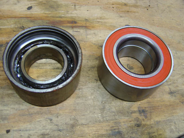
In this photo, the front kit has the green bearing with the larger M16 bolt, while the rear kit is orange with the M14 bolt.
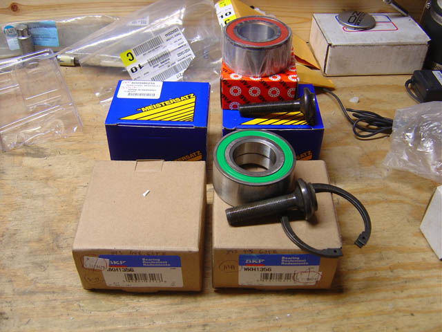
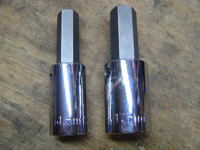
For the rear wheel axle bolt, you will need a 14mm allen / hex-bit socket. (FYI - the front requires a 17mm)
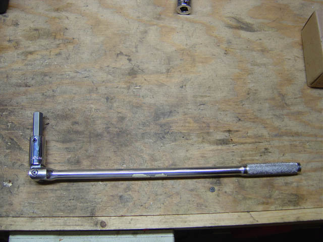
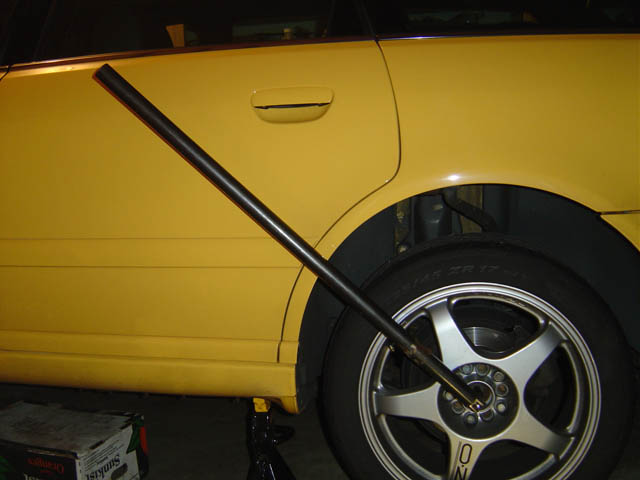
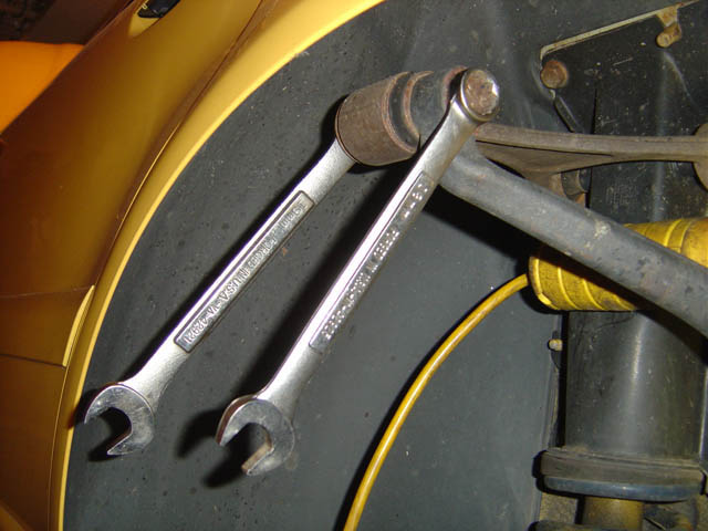
An 18" breaker bar is the minimum needed to remove/replace this bolt:
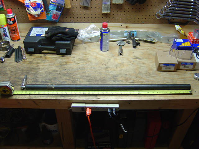
I've added a 38" black steel pipe to my breaker bar for more leverage in order to achieve the tightening torque spec (85ft-lbs +180deg for the rear, 105(?)ft-lbs +180deg for the front)
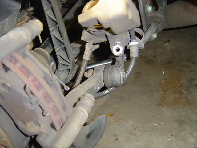
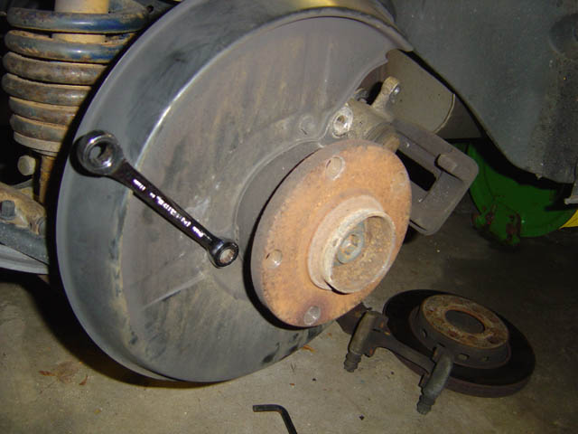
1.) Break the axle bolt free while the wheel is still on the ground:
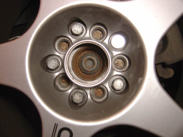
1.) As said above, do this while the wheel is on the ground - this photo is just for illustration of bolt:
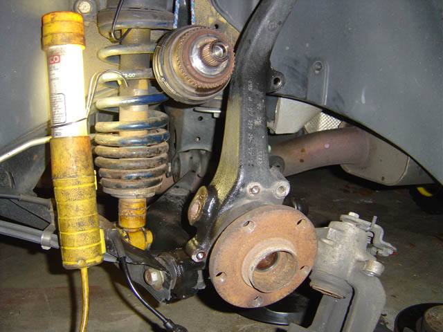
2.) Jack up car, put on jack stand, remove wheel
3.) Using a 15mm open end, hold the support nut in place while removing the 13mm bolt at the top of the brake caliper:
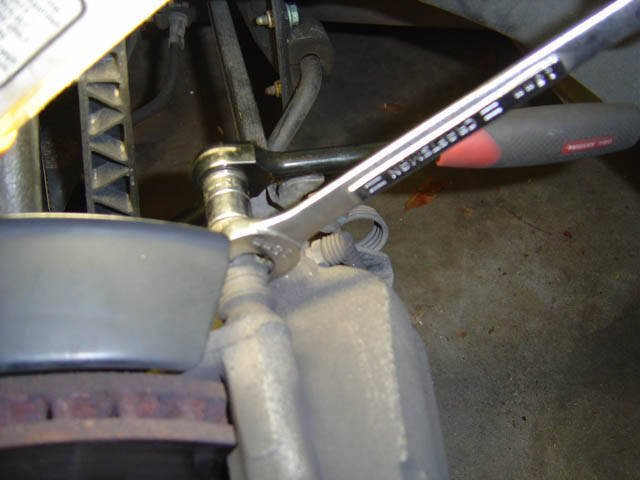
4.) Do the same for the bottom bolt:
5.) Remove the brake caliper and move out of the way:
6.) Remove the two 8mm allen bolts that hold the brake caliper bracket to the upright (note you can perform step #11 now if you need room due to that suspension link):
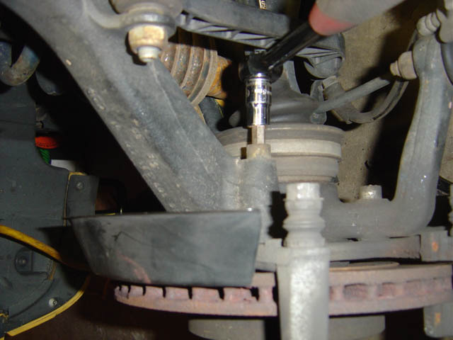
6.) Extra photo of this step:
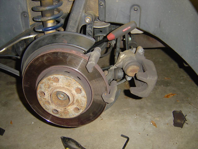
7.) With the top bolt out and the bottom one loose, the rotor can be removed. Continue and remove the bottom bolt completely and remove bracket:
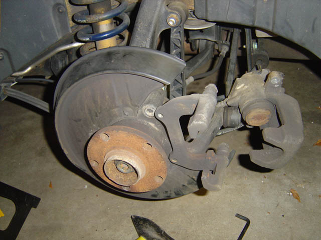
8.) Remove three 10mm bolts holding in splash guard, & also remove splash guard:
9.) Use 4mm(?) allen / hex-bit to remove retaining bolt holding in ABS sensor, then remove sensor as well.
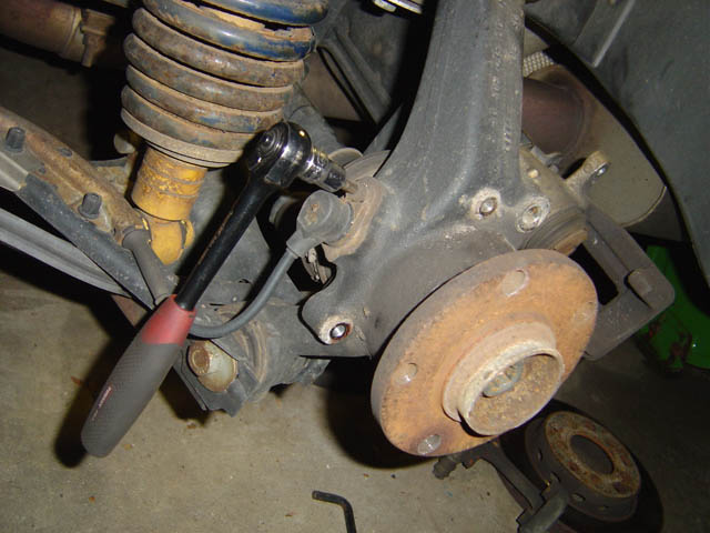
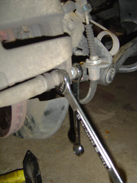
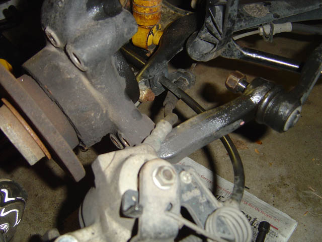
10.) Using 19mm wrench, remove nut on control arm connection. Just remove the nut, you likely won't be able to separate the arms:
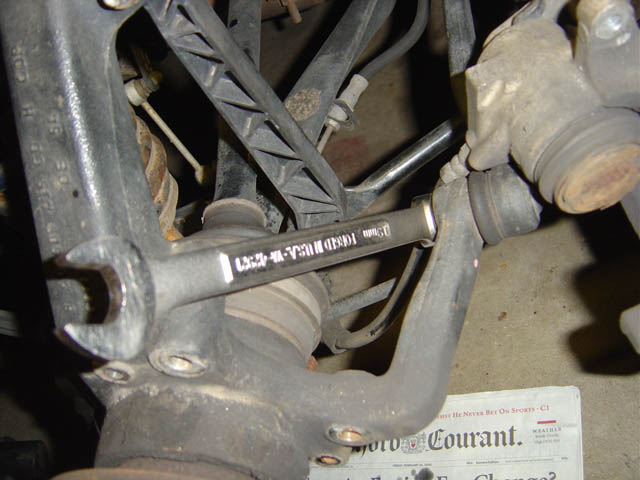
11.) Use two 17mm wrenches to remove the bolt through this suspension link:
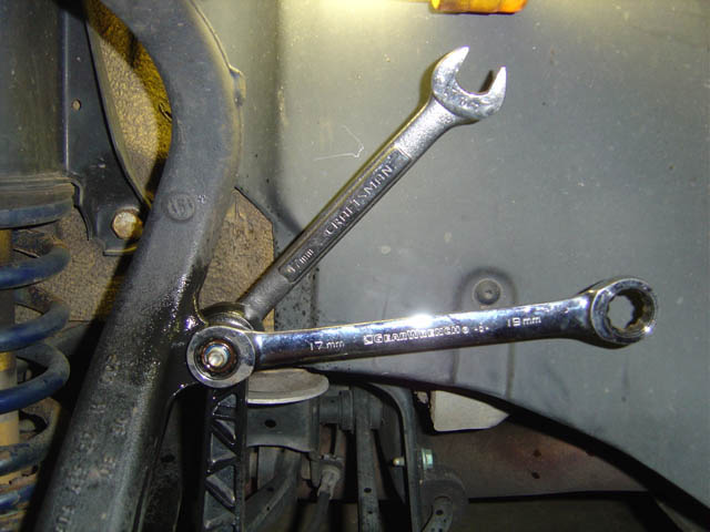
12.) Use two 19mm wrenches to remove this bolt at the top control arm:
13.) At this point, you can remove the drive shaft from the upright. I supported it with a bungee cord so it was up and out of my way:
14.) Take note of how the brake lines run around the suspension arms. Be sure to put this back this way when you reassemble, otherwise you'll have to disassemble again. Also note that by raising the drive shaft, I now have room to bang on that lower right control arm which is a pain to separate. We're not doing that yet though, as it will be easier later...
15.) Using two 19mm wrenches, remove this camber alignment bolt. Note that the washers are aligned to the bolt and do not spin freely, so don't try. It would be a good idea to mark the washer it's orientation so that you can put it back at the same rotation. You'll likely need an alignment after removing this, but you can at least try to get it back as close to how it was before.:
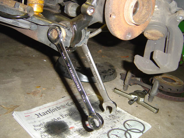
16.) After removing the above bolt, you can now remove the upright as well. It will still be connected by the lower right control arm, but now there won't be as much pressure on that connection. A whack or two with a mallet will free that connection which is held together by a tapered friction connection.
Success!
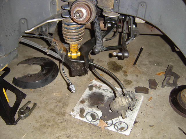
Now let's work on the bearing...
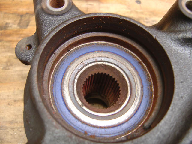
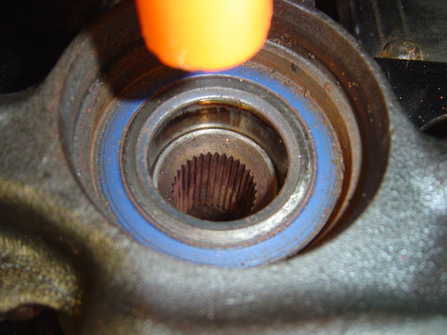
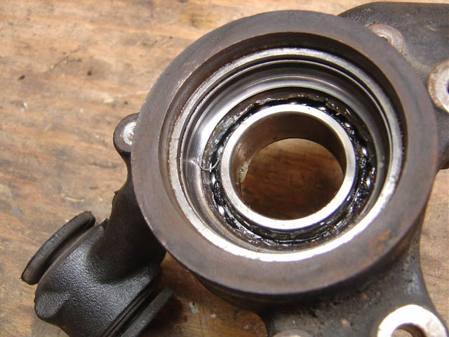
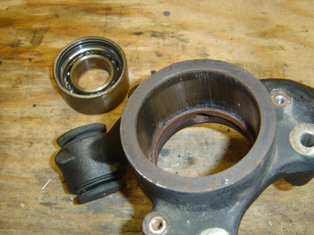
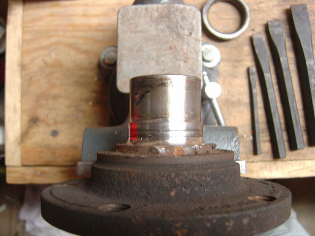
In this photo you can see in the center is the spline section which is part of the hub. Along the outer edge of the bearing you can see the cast iron lip - the bearing is pressed in from the other side (outside) and stops at this lip. So when we press out the bearing, we'll press from this side:
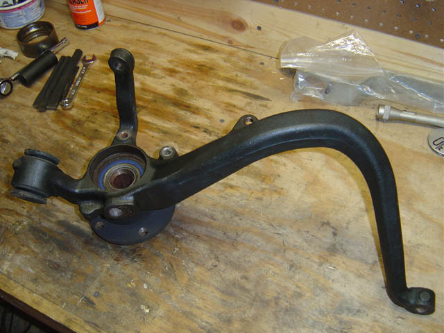
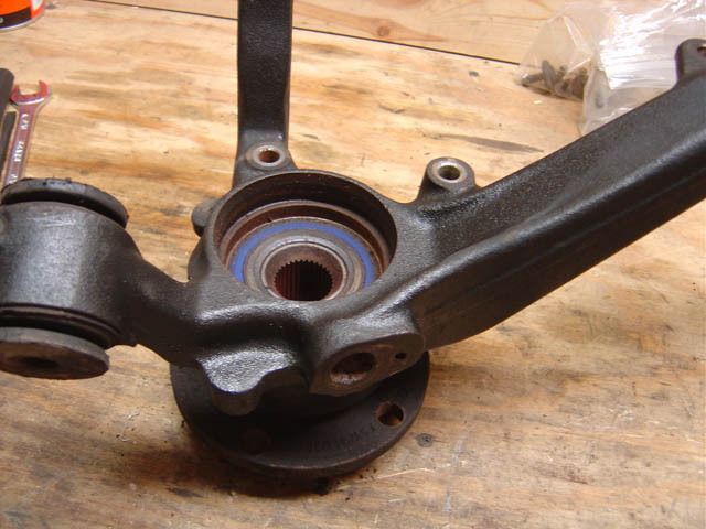
A zoomed-out shot of above:
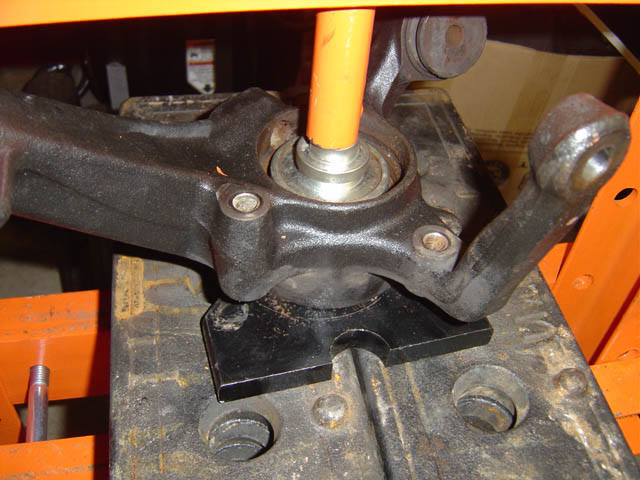
17.) First we will press out the hub from the bearing. There's less friction here than between the bearing and the upright, so we can just support the upright when pressing out the hub:
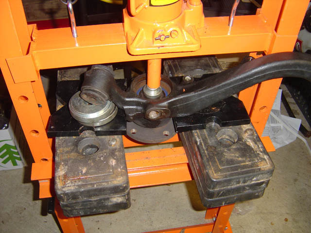
Close up:
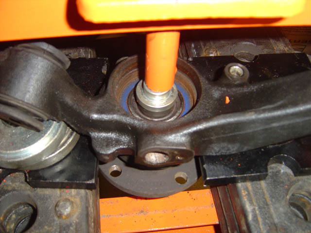
Photo just to show progress of hub being pressed out:
You'll most definitely end up with the bearing separating when complete:
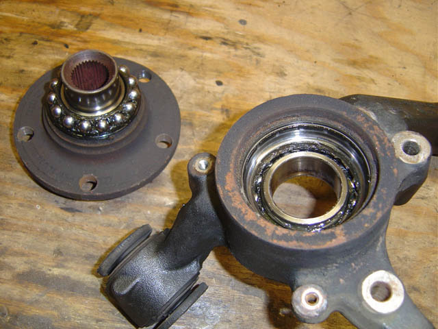
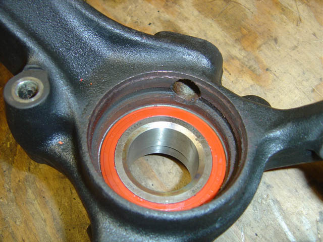
Here you can notice that there's a wide outer rim of shiny bearing housing which further illustrates the lip which is on the other side - thus the bearing comes out in this direction. Also note that the bearing is recessed about 1/4 inch from this outside edge:
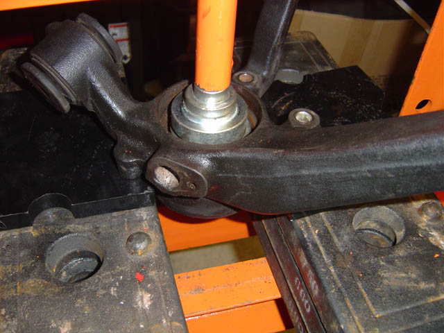
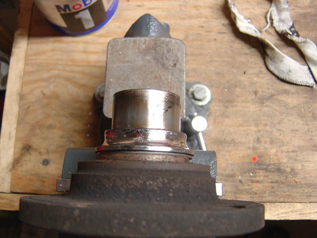
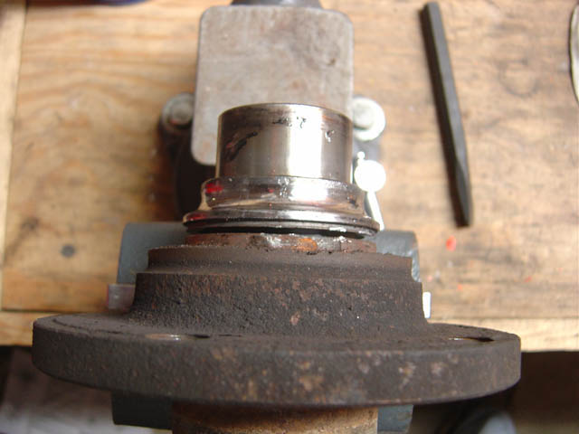
18.) Since there is that 1/4" of space where the bearing can move, we'll first place the upright on a flat surface. We're going to need to exert the most effort to initially break the bearing free, so thus the flat surface will give us the most stability:
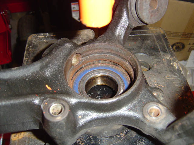
Once it breaks free, we look and see that sure enough it moved downwards about 1/4", now revealing a space below the lip:
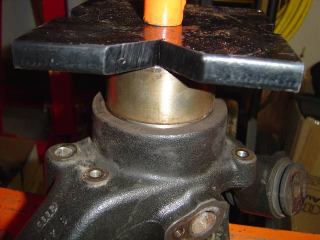
19.) Now we change our support to the outer sides, so we can press the bearing through:
Success!
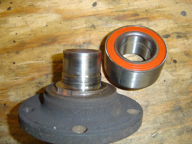
Old vs New:
20.) We still need to remove the part of the bearing that was stuck to the hub, so we place the hub in a vice and separate the two by hitting the joint with a chisel:
Starting to come apart:
Apart!
Note that the hub has a stepped diameter, wider at the outside (towards wheel) and narrower at the inside. The bearing has corresponding diameters. It is very important to note this now so that when inserting the bearing you press it in, in the correct orientation:
And thus, the bearing presses in with the wider diameter facing out as shown here:
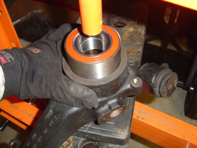
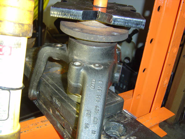
21.) The rear uprights are an awkward shape, so you may have to be creative to how you support the bottom when pressing in the bearing. The round disk I am using here directly supports that face of the upright. Be sure to use a flat surface when pressing the bearing - do not apply force directly to the center of the bearing as you will likely damage it.
Note: Some have suggested putting your new bearing in a freezer for a day and/or heat the upright - this should make insertion easier. Also, you may desire to lube the bearing/upright mating surface as well.
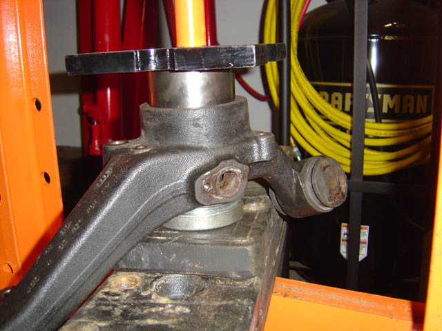
22.) Once the bearing is almost all of the way in, you'll need to press it in that extra 1/4" and you can't do that with a big flat plate on top. Instead, use the old bearing and stack that on the new one and then press on the old one. You'll end up pressing the old one in as well, for that 1/4" distance. Once you've done that, you can bang off the old one with a hammer as it's only partially inserted:
Confirming from the other side (inside), we see that the bearing was pressed all the way to the lip:
23.) Now we will press in the hub into the bearing. This time, it is vital to support the center of the bottom of the bearing (inner section). If we only support the upright, when we press in the hub it will blow apart the bearing similar to when we pressed out the hub. It's hard to distinguish in this photo, but my round disks underneath are only touching the bearing center, not any part of the upright.
That's it, now go put everything back together. Take your time to note the order you took things apart, so you don't have to do things twice. ie, don't forget the splash guard goes on before the rotor, be sure to put the brake caliper lines around the suspension links appropriately, etc.
Before putting on the wheel, I put in the axle bolt and tightened it just slightly snug with a wrench so the drive shaft was fully seated. I then put on the wheel, lowered the car to the ground, and tightened the axle bolt to the insane spec. With the 3' bar, I was able to achieve the 180deg.
Good luck!
For the iron uprights, the P/Ns I used are:
Front Kit: 4B0498625A
Rear Kit: 8D0598625A
Note: always confirm P/Ns for your car.
In this photo, the front kit has the green bearing with the larger M16 bolt, while the rear kit is orange with the M14 bolt.
For the rear wheel axle bolt, you will need a 14mm allen / hex-bit socket. (FYI - the front requires a 17mm)
An 18" breaker bar is the minimum needed to remove/replace this bolt:
I've added a 38" black steel pipe to my breaker bar for more leverage in order to achieve the tightening torque spec (85ft-lbs +180deg for the rear, 105(?)ft-lbs +180deg for the front)
1.) Break the axle bolt free while the wheel is still on the ground:
1.) As said above, do this while the wheel is on the ground - this photo is just for illustration of bolt:
2.) Jack up car, put on jack stand, remove wheel
3.) Using a 15mm open end, hold the support nut in place while removing the 13mm bolt at the top of the brake caliper:
4.) Do the same for the bottom bolt:
5.) Remove the brake caliper and move out of the way:
6.) Remove the two 8mm allen bolts that hold the brake caliper bracket to the upright (note you can perform step #11 now if you need room due to that suspension link):
6.) Extra photo of this step:
7.) With the top bolt out and the bottom one loose, the rotor can be removed. Continue and remove the bottom bolt completely and remove bracket:
8.) Remove three 10mm bolts holding in splash guard, & also remove splash guard:
9.) Use 4mm(?) allen / hex-bit to remove retaining bolt holding in ABS sensor, then remove sensor as well.
10.) Using 19mm wrench, remove nut on control arm connection. Just remove the nut, you likely won't be able to separate the arms:
11.) Use two 17mm wrenches to remove the bolt through this suspension link:
12.) Use two 19mm wrenches to remove this bolt at the top control arm:
13.) At this point, you can remove the drive shaft from the upright. I supported it with a bungee cord so it was up and out of my way:
14.) Take note of how the brake lines run around the suspension arms. Be sure to put this back this way when you reassemble, otherwise you'll have to disassemble again. Also note that by raising the drive shaft, I now have room to bang on that lower right control arm which is a pain to separate. We're not doing that yet though, as it will be easier later...
15.) Using two 19mm wrenches, remove this camber alignment bolt. Note that the washers are aligned to the bolt and do not spin freely, so don't try. It would be a good idea to mark the washer it's orientation so that you can put it back at the same rotation. You'll likely need an alignment after removing this, but you can at least try to get it back as close to how it was before.:
16.) After removing the above bolt, you can now remove the upright as well. It will still be connected by the lower right control arm, but now there won't be as much pressure on that connection. A whack or two with a mallet will free that connection which is held together by a tapered friction connection.
Success!
Now let's work on the bearing...
In this photo you can see in the center is the spline section which is part of the hub. Along the outer edge of the bearing you can see the cast iron lip - the bearing is pressed in from the other side (outside) and stops at this lip. So when we press out the bearing, we'll press from this side:
A zoomed-out shot of above:
17.) First we will press out the hub from the bearing. There's less friction here than between the bearing and the upright, so we can just support the upright when pressing out the hub:
Close up:
Photo just to show progress of hub being pressed out:
You'll most definitely end up with the bearing separating when complete:
Here you can notice that there's a wide outer rim of shiny bearing housing which further illustrates the lip which is on the other side - thus the bearing comes out in this direction. Also note that the bearing is recessed about 1/4 inch from this outside edge:
18.) Since there is that 1/4" of space where the bearing can move, we'll first place the upright on a flat surface. We're going to need to exert the most effort to initially break the bearing free, so thus the flat surface will give us the most stability:
Once it breaks free, we look and see that sure enough it moved downwards about 1/4", now revealing a space below the lip:
19.) Now we change our support to the outer sides, so we can press the bearing through:
Success!
Old vs New:
20.) We still need to remove the part of the bearing that was stuck to the hub, so we place the hub in a vice and separate the two by hitting the joint with a chisel:
Starting to come apart:
Apart!
Note that the hub has a stepped diameter, wider at the outside (towards wheel) and narrower at the inside. The bearing has corresponding diameters. It is very important to note this now so that when inserting the bearing you press it in, in the correct orientation:
And thus, the bearing presses in with the wider diameter facing out as shown here:
21.) The rear uprights are an awkward shape, so you may have to be creative to how you support the bottom when pressing in the bearing. The round disk I am using here directly supports that face of the upright. Be sure to use a flat surface when pressing the bearing - do not apply force directly to the center of the bearing as you will likely damage it.
Note: Some have suggested putting your new bearing in a freezer for a day and/or heat the upright - this should make insertion easier. Also, you may desire to lube the bearing/upright mating surface as well.
22.) Once the bearing is almost all of the way in, you'll need to press it in that extra 1/4" and you can't do that with a big flat plate on top. Instead, use the old bearing and stack that on the new one and then press on the old one. You'll end up pressing the old one in as well, for that 1/4" distance. Once you've done that, you can bang off the old one with a hammer as it's only partially inserted:
Confirming from the other side (inside), we see that the bearing was pressed all the way to the lip:
23.) Now we will press in the hub into the bearing. This time, it is vital to support the center of the bottom of the bearing (inner section). If we only support the upright, when we press in the hub it will blow apart the bearing similar to when we pressed out the hub. It's hard to distinguish in this photo, but my round disks underneath are only touching the bearing center, not any part of the upright.
That's it, now go put everything back together. Take your time to note the order you took things apart, so you don't have to do things twice. ie, don't forget the splash guard goes on before the rotor, be sure to put the brake caliper lines around the suspension links appropriately, etc.
Before putting on the wheel, I put in the axle bolt and tightened it just slightly snug with a wrench so the drive shaft was fully seated. I then put on the wheel, lowered the car to the ground, and tightened the axle bolt to the insane spec. With the 3' bar, I was able to achieve the 180deg.
Good luck!
Last edited by Mark P; 02-08-2010 at 06:33 AM.


 02-16-2006, 01:54 PM
#7
AudiWorld Uber User

Join Date: Mar 2000
Posts: 66,965
Likes: 0
Received 0 Likes
on
0 Posts
A arm so when you when you reassemble, you can restore the alignment to it's original setting (assuming that was any good to begin with).
Otherwise nice work!! I tried this once...royal PITA bearing would not come out with a hub shark and impact gun. Eventually we gave up, pulled the upright and ran it to a shop to press it out. Sucks when you start working thinking you will be done in 3 hours, and 2 days later you're putting the car back together.
Otherwise nice work!! I tried this once...royal PITA bearing would not come out with a hub shark and impact gun. Eventually we gave up, pulled the upright and ran it to a shop to press it out. Sucks when you start working thinking you will be done in 3 hours, and 2 days later you're putting the car back together.


