When you click on links to various merchants on this site and make a purchase, this can result in this site earning a commission. Affiliate programs and affiliations include, but are not limited to, the eBay Partner Network.
Team,
Today when driving, I got a MIL and the car started running a bit different;. Pulled codes (VCDS) and got
000023 - Bank 1; CMP Sensor 3 (G300) / Engine Speed Sens (G28)
P0017 - 001 - Incorrect Correlation - MIL ON
I will reset and see if the problem goes away (not really likely....)
On W12 - does anyone know there the speed sensor (G28) is located? I expect somewhere close to merge point between gearbox and engine since it measures flywheel using a Hall sensor?
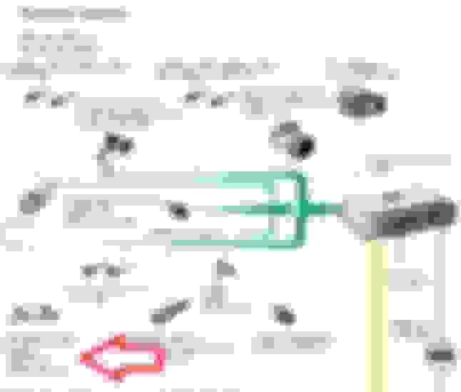
And the G300 - CMP - is that the camshaft sensor that sits behind the heads, towards firewall? Red circle in this picture?
Bank 1 means drivers side (US car), right?
Speed sensor location: Not sure; I never had issue w/ mine.
Cam sensors: I can't get oriented in your pic, but yes they are on the back of the heads. One per cam, so two on each side. Major pain in butt to screw the allen head back in. Seems like that is in your circled pic--at least the bolt or one like it. Out is not so bad, but in can be a world of pain...literally. They are blind, since bolt unscrews toward the firewall in that tight space. I did driver's side first (exhaust IIRC), which was not outrageously bad. Then I did the passenger side when it came up more recently. Probably spent 2-3 hours turning allen head back in, like 1/6 of a turn a time, then reposition wrench (1-10 minutes each time), and repeat. 6 x for one revolution, w/ maybe a dozen threads? Even funner: not enough space to fit in any allen wrench I could figure out. So I had to use an allen tip, put that into socket in bolt, then turn that with a little open end wrench. Repeat 50-100x. Drop at least several times and retrieve (hopefully...) w/ a magnet tool if it doesn't come out the bottom. If you have an XL hand like me, it will also be scratched up just like giving a cat a bath for fun. The problem on the passenger side is there is also a bracket the same allen head bolt passes through. That bracket will likely sort of jam the shaft of the bolt enough that you can't turn it w/ your fingers...that can barely turn it even if it goes well like on my driver's side.
If you are a go on this, re post and I can find the Bosch sensor part #. Then you can get it for like ⅓ of dealer price from places like AutohausAZ. You will want the connector housing from a dealer too, in advance. Doesn't cost a lot anyway. The passenger side especially will be very heat soaked, and at least 50/50 odds you will break it while disconnecting. Not good on exhaust one where the plug basically falls downward when the lock tab and rest of it are still in one piece. From BTDT, led to a second manifold pull after a temporary tie strap patch once I had the connector housing.
Cam sensors: I can't get oriented in your pic, but yes they are on the back of the heads. One per cam, so two on each side.
That is my engine - outside the car a few years back. Looking forward as if there was no firewall and you are looking at the back of the engine. Drivers side is to the left in the picture.
Originally Posted by MP4.2+6.0
One per cam, so two on each side. Major pain in butt to screw the allen head back in. Seems like that is in your circled pic--at least the bolt or one like it. Out is not so bad, but in can be a world of pain...literally. They are blind, since bolt unscrews toward the firewall in that tight space. I did driver's side first (exhaust IIRC), which was not outrageously bad. Then I did the passenger side when it came up more recently. Probably spent 2-3 hours turning allen head back in, like 1/6 of a turn a time, then reposition wrench (1-10 minutes each time), and repeat. 6 x for one revolution, w/ maybe a dozen threads? Even funner: not enough space to fit in any allen wrench I could figure out. So I had to use an allen tip, put that into socket in bolt, then turn that with a little open end wrench. Repeat 50-100x. Drop at least several times and retrieve (hopefully...) w/ a magnet tool if it doesn't come out the bottom. If you have an XL hand like me, it will also be scratched up just like giving a cat a bath for fun. The problem on the passenger side is there is also a bracket the same allen head bolt passes through. That bracket will likely sort of jam the shaft of the bolt enough that you can't turn it w/ your fingers...that can barely turn it even if it goes well like on my driver's side.
If you are a go on this, re post and I can find the Bosch sensor part #. Then you can get it for like ⅓ of dealer price from places like AutohausAZ. You will want the connector housing from a dealer too, in advance. Doesn't cost a lot anyway. The passenger side especially will be very heat soaked, and at least 50/50 odds you will break it while disconnecting. Not good on exhaust one where the plug basically falls downward when the lock tab and rest of it are still in one piece. From BTDT, led to a second manifold pull after a temporary tie strap patch once I had the connector housing.
Wow, sounds like a lot of fun.... And maybe a smart thing to see if I can prepare some kind of special tool to use. And order a few extra of those screws. Are all four sensors the same? Would be great to get those part numbers!
From this I deduct that it's not the speed sensor, since A) the car doesn't run without it, and B) I assume all four CMPs would throw error codes if it was....
So it looks like it's my exhaust CMP on bank 1. And now only the determination of the driver versus passenger side remains (which bank?).
The first text seem to infer that cylinder 1-6 is bank 1 and cylinder 7-12 is bank 2.
Last edited by carl viking; 09-23-2017 at 02:33 AM.
Thank you!
Do you have the legend to the picture as well? Does this look right (found it on a Vortex forum)? If so - It's my passenger side, which MP said was the worst one. Surprise! Not....
6 - Camshaft Position (CMP) sensor 3 (-G300-) ‹› For exhaust camshaft ‹› Cylinder bank 1
7 - Camshaft Position (CMP) sensor 2 (-G163-) ‹› For intake camshaft ‹› Cylinder bank 2
8 - Camshaft Position (CMP) sensor (-G40-) ‹› For intake camshaft ‹› Cylinder bank 1
10 - Camshaft Position (CMP) sensor 4 (-G301-) ‹› For exhaust camshaft ‹› Cylinder bank 2
Last edited by carl viking; 09-23-2017 at 02:31 AM.
That is my engine - outside the car a few years back. Looking forward as if there was no firewall and you are looking at the back of the engine. Drivers side is to the left in the picture.
Wow, sounds like a lot of fun.... And maybe a smart thing to see if I can prepare some kind of special tool to use. And order a few extra of those screws. Are all four sensors the same? Would be great to get those part numbers!
1J0973723 should be the cam sensor wiring connector housing you get from dealer. In $10 range if you get online discount type price. If you are familiar with these generally, you shatter old one with some decent pliers and then extract the terminals (still intact--don't go wild squeezing) and plug into new one. Remove the little purple lock clip before extracting terminals from old one, or putting them into new one. Lock clip going back in (new one is supplied inside clip) is the last step after terminals are fully seated. With 10 years of heat soak the plastic generally just shatters pretty easily for me. Expect the wiring jacket to be heat fried over on passenger side too. Mine had outer jacket or tape burned away, but inner conductors seemed okay. Hard to resplice a new factory lead in there, so I worked w/ what I had. I retaped it for protection. Mark individual wires by the way right away before any tinkering w/ connector. Assuming they have heat issues, you can't distinguish them by color or otherwise once out of connector, and presumably their relative position is critical. I put little pieces of numbered electrical tape on each until I had them swapped to new connector. It's also not so obvious which way they are oriented in the connector housing (in line or perpendicular), so pay attention to the old one and/or look at sensor receiving end for reference.
It's a 5mm allen head, so basically have a varied collection of those. The problem on the passenger side as I recall is there is also very little room to turn the wrench because of other immovable stuff. IIRC I also removed one of the ECU's from its mount point because the engine harness passes right in that area and is essentially immovable until one of the ECU's is freed up. Even then, it is awkward to work around per my description. It's both the bracket I mentioned as well as the wiring harness that are more problematic on passenger side. If I remember my work, I had also pulled upper half of passenger air box, cut various wiring tie down straps, moved some O2 wiring to the side and so on to free up space. In this dive I also realized one of the heater hose elbow fittings was starting to rot out--given the visible pink deposits on outside. So on the re-dive to do the connector I did that elbow + hose too. Managable w/ upper intake manifold out; bottom/other end of it not accessible otherwise.
...
From this I deduct that it's not the speed sensor, since A) the car doesn't run without it, and B) I assume all four CMPs would throw error codes if it was....
So it looks like it's my exhaust CMP on bank 1. And now only the determination of the driver versus passenger side remains (which bank?).
The first text seem to infer that cylinder 1-6 is bank 1 and cylinder 7-12 is bank 2.
When Audi references 4 banks on a W12, bank 1 is US passenger side forward, bank 2 is same side in rear, bank 3 is US drivers forward, and bank 4 is US drivers rear. When they only reference two banks, then (like the V8) it is bank 1 for whole passenger side, head, etc., and bank 2 for driver's side. Confusing that two things called bank 2 are in completely different places on motor depending on what part you are dealing with. I only recall the bank 1-4 nomenclature coming up with O2 sensors and related exhaust, since there are four sensors forward as well as 4 header assemblies.
[QUOTE=carl viking;25041655]Thank you!
Do you have the legend to the picture as well? Does this look right (found it on a Vortex forum)? If so - It's my passenger side, which MP said was the worst one. Surprise! Not....
1 - Mass Air Flow (MAF) sensor 2 (-G246-) with Intake Air Temperature (IAT) sensor 2 (-G299-)
�For cylinder bank 2 (cylinders 7 to 12)�Removing and installing => [ Installing ] See: Air Flow Meter/Sensor\Service and Repair\Mass Air Flow Sensor 2�The intake channels cross in the center of the intake manifold. The Mass Air Flow (MAF) sensor 2 (-G246-) on the right side (as seen in driving direction) therefore measures the intake air mass for cylinder bank 2 on the left side (as seen in driving direction). The same applies to the Intake Air Temperature (IAT) sensor 2 -G299-.
2 - Electrical connections for oxygen sensors
3 - Throttle valve control module 2 (-J544-)
�with Throttle drive 2 (power accelerator actuation) (-G296-), Angle sensor 1 (on throttle drive 2 power accelerator actuation) (-G297-) and Angle sensor 2 (on throttle drive 2 power accelerator actuation) (-G298-)�For cylinder bank 2 (cylinders 7 to 12)�Pay attention to first phrase in above mentioned note
4 - Engine Control Module (ECM) 2 (-J624-)
�In Electronics box in plenum chamber�Mark before disconnecting, to prevent switching with Engine Control Module (ECM) 1
5 - Engine Control Module (ECM) (-J623-)
�In Electronics box in plenum chamber�Mark before disconnecting, to prevent switching with Engine Control Module (ECM) 2
6 - Camshaft Position (CMP) sensor 3 (-G300-)
�For exhaust camshaft�Cylinder bank 1
7 - Camshaft Position (CMP) sensor 2 (-G163-)
�For intake camshaft�Cylinder bank 2
8 - Camshaft Position (CMP) sensor (-G40-)
�For intake camshaft�Cylinder bank 1
9 - Engine speed (RPM) sensor (-G28-)
10 - Camshaft Position (CMP) sensor 4 (-G301-)
�For exhaust camshaft�Cylinder bank 2
11 - Throttle valve control module (-J338-)
�with Throttle drive (power accelerator actuation) (-G186-), Angle sensor 1 for throttle drive (power accelerator actuation) (-G187-) and Angle sensor 2 for throttle drive (power accelerator actuation) (-G188-)�For cylinder bank 1 (cylinders 1 to 6)
12 - Mass Air Flow (MAF) sensor (-G70-) with Intake Air Temperature (IAT) sensor (-G42-)
�For cylinder bank 1 (cylinders 1 to 6)�Removing and installing => [ Removing ] See: Air Flow Meter/Sensor\Service and Repair\Mass Air Flow Sensor 2�The intake channels cross in the center of the intake manifold. The Mass Air Flow (MAF) sensor (-G70-) on the left side (as seen in driving direction) therefore measures the intake air mass for cylinder bank 1 on the right side (as seen in driving direction). The same applies to the Intake Air Temperature (IAT) sensor (-G42-).
13 - Mechanical EGR valve
14 - Mechanical EGR valve
15 - Secondary Air Injection (AIR) pump motor 2 (-V189-)
�For cylinder bank 2�In lower part of air filter housing
16 - Secondary Air Injection (AIR) pump motor (-V101-)
�For cylinder bank 1�In lower part of air filter housing
 09-22-2017, 03:59 PM