| Tech Article Title |
Author |
Date
|
| Installing a Euro A6 RNS-E Nav unit in a B5 S4 |
Matthew Taylor
|
2005 |
Required Parts:
- 4B0 RNS-E unit from Euro A6
- RNS-E adapter harness for B5 platform cars
- Diversity antenna adapter
- GPS antenna
- 4’ CAT5 cable
- Radio Shack 2-pin locking connector
Required tools:
- T20 torx driver
- VAG radio removal tools (4)
- Wire cutters
- Wire strippers
- Small needle-nose pliers
- Heat-shrink wire wrap
CAN Pin table:
| |
CAN H |
CAN L |
| Symphony Harness |
See Fig. 1-2 |
See Fig. 1-2 |
| RNS-E harness |
Connector D, Pin 9 |
Connector D, Pin 10 |
| Cluster Harness |
Pin 5 |
Pin 6 |
Installation Steps:
Part 1 - Verify that your car has the required CAN connections behind the dashboard.
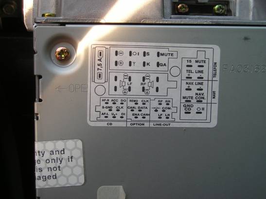
Using the radio removal tools, slide the OEM Symphony unit out of the dash far enough to expose the wiring harnesses. Look at the top connector to the left of the rear of the unit (Fig. 1-1). Look at the left-center and right-top pins on the center cluster of pins (Fig. 1-2), the will be marked as CAN L and CAN H respectively on the diagram on top of the unit (Fig. 1-3). If the wires leading to these pins are orange, there’s a good chance the CAN signals are already in place and no modification to the wiring harnesses will be necessary. If the wires are grey, chances are you’ll need to tap into the CAN signals behind your instrument cluster.
Figure 1-1

Figure 1-2. (CAN H marked in blue, CAN L marked in red)

Figure 1-3.
Part 2 - Prepare a twisted pair of wires for the CAN signals.
Any pair of ~22ga wires will do for the CAN wires; I used a 4’ length of CAT5 cable because the wire pares were color coded, already twisted, and protected by an outer jacket. My instructions will be tailored to the use of a CAT5 cable, but can be adjusted to work with any pair of wires. Cut the ends from a 4-foot CAT5 patch cable. Using a razor blade, cut away the outer jacketing 1” back from each end of the cable. Choose one of the colored wire pairs to carry your CAN signals, cut the other three pairs off where the outer jacketing stops on each end of the cable. Strip the ends of the wire pairs on each end of the cable. On one end of the cable, slide a heat-shrink tube over the cable, then crimp the male pins from the radio shack locking connector to the ends of the wire pair. Insert the pins into the male locking connector, make sure they lock into place, and shrink the heat-shrink tube over the area where the jacketing ends (Fig. 2-1). This end of the cable will be the end that connects to the RNS-E harness.
Figure 2-1.

Part 3 - Tap into the instrument cluster for CAN signals.
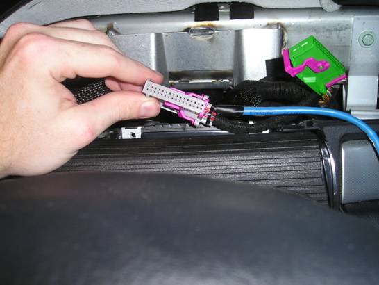
Remove the plastic trim piece from in front of the instrument cluster by pulling it upwards and towards you. Using a HIGH QUALITY T20 Torx driver, remove the two T20 screws holding the cluster in place (Fig. 3-1). These screws are in tight, and are in a very bad position to remove should you strip the heads by using a poor quality tool. Pull the cluster out towards you using the two adjustment stalks. It helps to have your steering wheel in the lowest position to give yourself as much room as possible to maneuver the cluster. Reach behind the cluster and disengage the locking tabs on the three wiring harnesses by pulling them away from the back of the cluster housing. Once the harnesses are free, remove the cluster. The grey center harness contains the pins you will need to tap for the CAN signals (Fig. 3-2). You’ll need to remove the outer housing of the harness by sliding off the purple cap on the end of the harness where the wires enter, cut the ziptie holding the wires to the harness housing, and pull the wires and the white inner harness straight out of the housing (Fig, 3-3). Pins 5 and 6 of the white inner harness are the pins for the CAN-H and CAN-L signals respectively. Inspect the inner harness for spare pins with no wires attached. If there are no unattached pins to be found in this harness, remove the housing from the green harness on the right using the same technique used to remove the grey housing and extract the two spare pins found in the connector (Fig. 3-4, Fig. 3-5).
Figure 3-1.

Figure 3-2.

Figure 3-3.
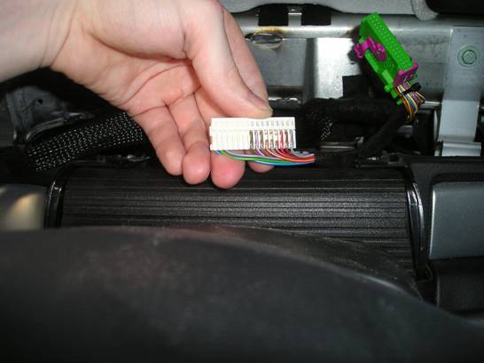
Figure 3-4.

Figure 3-5.

Get the cable prepared in Step 2, and slide a heat-shrink tube over the end of it that does not have the locking connector. Crimp the spare pins from the cluster harness onto the stripped ends of the twisted wire pair on this end of the cable, then shrink the heat-shrink tubing over the area where the jacketing ends. Insert the pins into slots 5 and 6 of the white inner harness from the center cluster cable (Fig. 3-6). Be sure to take note which color wire is CAN H and which color wire is CAN L. Mark the connector on the opposite end of the cable CAN H and CAN L accordingly. Route the end of the cable with the locking connector behind the cluster area and down into the radio and HVAC mounting area (Fig. 3-7).
Reassemble the cluster harness connectors by sliding the outer connector housings back over the white inner harnesses, replacing the purple end-caps, and replacing the zipties (Fig. 3-8). Reconnect the harnesses to the back of the cluster by opening the locking levers all the way, then pressing them into the sockets on the cluster. Push the cluster back into position, then replace the T20 screws and the plastic trim piece. You now have active CAN connections to your radio area.
Figure 3-6.

Figure 3-7.

Figure 3-8.
Part 4 - Modifying the RNS-E Harness.
Plug the RNS-E harness into the back of the RNS-E unit. Using the wiring diagram on top of the unit, find the D connector and locate pins 9 and 10 of this connector. These are the CAN H and CAN L connections to the RNS-E unit, respectively. Trace these two wires to the other end of the harness plug and cut them at the plug (Fig. 4-1). Strip the ends of the wires, and crimp the female pins from the Radio Shack locking connector to them. Using the marked male connector you marked in part 4 as a reference, mark the female Radio Shack locking connector plug CAN H and CAN L so that CAN H and CAN L on the two connectors match when they are connected. Insert the connected pins into the female Radio Shack locking connector plug, making sure to insert the pin connected to CAN H on the side of the connector marked CAN H and the pin connected to CAN L on the side of the connector marked CAN L (Fig. 4-2). Be sure to insert them far enough into the connector that you hear them click.
Figure 4-1.

Figure 4-2.

Part 5 - Connecting the RNS-E unit.
Connect all four of the open ends of the RNS-E connector to the OEM harnesses in the dashboard. Connect the two Radio Shack locking connector plugs for the CAN signals together, again making sure that CAN H and CAN L match up on the two plugs (Fig. 5-1). Connect the two-pin end of the diversity antenna adapter to the dual connector on the lower right rear of the RNS-E unit. Connect the other ends of the diversity antenna adapter to the antenna lead and to the diversity lead. Connect the GPS antenna cable to the connector on the top left rear of the RNS-E unit, next to the unit fan. Tuck the excess wiring into the radio housing in the console, and slide the RNS-E unit into the dash until it locks into place. Turn the car on, power up the unit, and enter the SAFE radio code. Verify that the lighting on the unit illuminates when the car’s headlights are turned on, and that the unit turns on and off with the ignition. If both of these functions work, the CAN cables are properly connected.
Figure 5-1.

Part 6 - VAG Coding.
Using Ross-Tech VAG-COM, open ‘Controller 17 - Instruments’. Select ‘10 - Adaptation’ from the menu on the right of the open controller screen. Enter ‘062’ in the Channel setting and click the Read button, the setting will likely be 0 by default. Change the setting to 5, click Test, and verify that 5 appears in the Test area. Apply the changes. The RNS-E should now display track and navigation information in the instrument cluster.
Finished pictures, before faceplate modification:


