| Tech Article Title |
Author |
Date
|
| Exhaust mod with switch control |
Marc3.2TT |
2006 |
Step 4: Testing the leads for correct voltage
This step serves a
dual-purpose: to make sure every wire is connected properly, and to
determine which side of the control wire goes to which wire that will
be run through to the switch.
a) Verify that you have 0 resistance between the ground (black) wire and the star-shaped "hub"
b) Verify that you have 0 resistance between the +12V (red) wire and the "87 F Diesel" terminal
c) Verify that you have 12 Volts when measuring between the +12V (red) and ground (black) wires - note that the ignition must be turned to ON (engine not necessarily running) to have 12V across these leads
d) Now connect your voltmeter between the ECU or Solenoid (brown or orange) and ground (black), strap it to a visible place on your dashboard and go for a ride! But first...
e) Replace the relays and their connectors in the relay panel (run Step 2-b backwards)
f) Screw the relay panels back where they belong (run Step 2-a backwards)
g) Reinstall the lower dash panel and fuse panel & its cover (run Steps 1-e/d/c/b/a backwards)
h) Reconnect the battery!
i) Ok, now you're on the road, and one of your ECU or Solenoid leads displayed on your voltmeter. If the voltmeter reads 12 Volts or more *constantly* this means you have the Solenoid lead. Otherwise, it will either read around 3.6 Volts (that means the flap should be opened) or close to 0 Volts (flap closed). Note that during your test drive, it will keep the flap always opened since the ECU is not grounding the Solenoid. You will definitely hear the difference when the RPM's are between idle and 3100!! =) Now connect the other ECU or solenoid wire, and confirm that the other voltage behavior is observed. Also note that, since the ECU is no longer connected to the Solenoid, an error code will be thrown by the ECU and the Check Engine light will go on. Not to worry though, it will soon disappear after you connect the switch.
Step 5: Onto the switch setup!
As I mentioned in the beginning (i.e. a while ago...) the switch must be a 3-way DPDT ON-ON-ON toggle switch in order to "safely" have all 3 modes.
Here are four switches I purchased online, as I couldn't find one with the right specs locally:
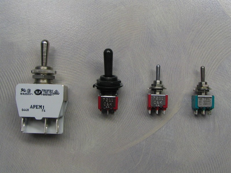
From left to right, we have the following part numbers from the manufacturers:
- APEM 644H/2
- ITT/C&K 7211TZQE22
- ITT/C&K 7211SYZQE
- Electroswitch A232S1YZQ
I ended up picking the black ITT one, since it looks the least conspicuous in the TT's centre console. Also its actuator is a fair bit larger than the other two small ones while having the same small connector size.
Here's a sample diagram of the switch I ended up using:
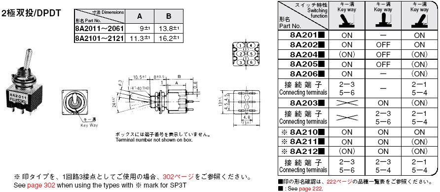
What's most valuable in this diagram is the "connecting terminals" row that shows which of the switch's poles are connected together in every position of the switch's actuator.
Note that it says the P/N for the one we need is "8A210" in this chart, but the complete P/N for the switch is actually 7211SYZQE, which has the same electrical properties as the 7211TZQE22 I ended up using (just different mechanical parts).
Now given the wiring diagram I drew in the first post, and the electrical requirements of this mod, let's assume that:
A = resistor w/ +12V lead
B = wire from ECU
C = solenoid end
D = ground
The intent is to have three possible modes:
A+B = ECU connected to resistor = "loud"
B+C = ECU connected to solenoid = "normal"
C+D / A+B = ECU to resistor, solenoid to ground = "quiet"
Now all that's left is to match a wire to a post (or two), as follows:
A = 3
B = 2
C = 1 and 5
D = 6
Going by the switch diagram above, there are three positions:
Left = 2+3 / 5+6 = B+A / C+D = "quiet mode"
Center = 2+3 / 5+4 = B+A / C+? = "loud mode"
Right = 2+1 / 5+4 = B+C / C+? = "normal mode"
I know this sounds a bit complicated, but matching the switch poles to the correct leads is crucial.
Let's wire up the switch then!
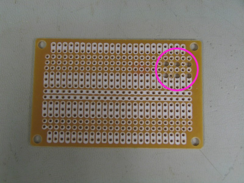
Since the +12V lead needs to first be connected through a resistor before hitting the switch, and to make things cleaner, I decided to use a PC board.
a) Create holes large enough in the PCB for the switch to fit:
b) Cut the PCB down in size as we won't need the entire surface:

c) Make sure the switch fits snug into the holes:
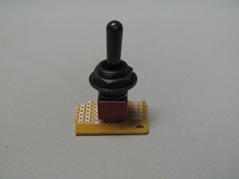
d) The switch leads should stick out the back a bit for soldering purposes:

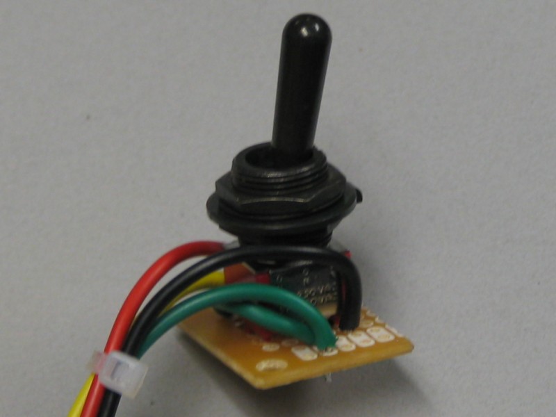
e) Here's one side of the switch where poles 1, 2, and 3 are connected to C, B and A respectively (where A is the +12V lead first going through the resistor):
f) Here's the other side of the switch with poles 5 and 6, connected to C again (green loop wire) and D respectively:
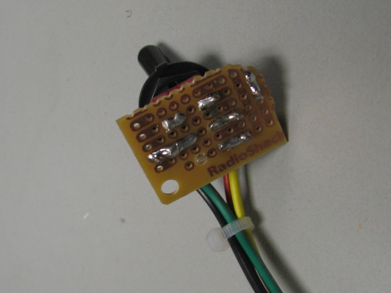
g) Here is the "behind-the-scenes" soldering job:
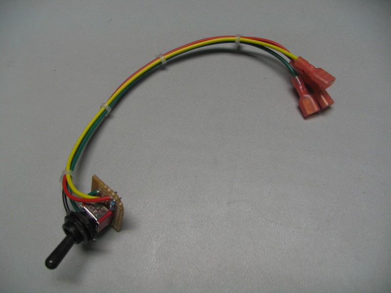
h) I connected the end of these short leads to female connectors, and voil?! the switch is ready for action:
[Page1][Page2][Page3][Page5]