|
|
 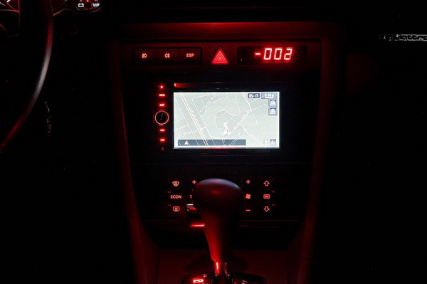 As you can see the red buttons matches our interior lighting very well. Now for the actual installation. Adaptors/connectors needed: The following adaptors are made by Metra and can be purchased through the excellent site: http://www.audiooutfitter.com
For the non-Bose unit, the Symphony radio provides amplification for the front channel speakers only. The back speakers have an amplifier built in with line out signals from the Symphony unit. The Avic-D3 can provide amplification for both front and rear speakers channels. Before we begin I have to say that I could not figure out how to get to the rear speakers in our car so I ended up using the built in amplifier for rear channels. OK, here is the connection for my setup. Remember, if you have Bose radio or want to power all speakers from the Pioneer unit, you will have to figure out how to connect/modify your wiring. Refer to the following pin-out diagram for the Symphony unit. You will have to solder the following wires from the Metra harness to the AVIC harness and cover the joints with tape or better, heat shrink tubing. 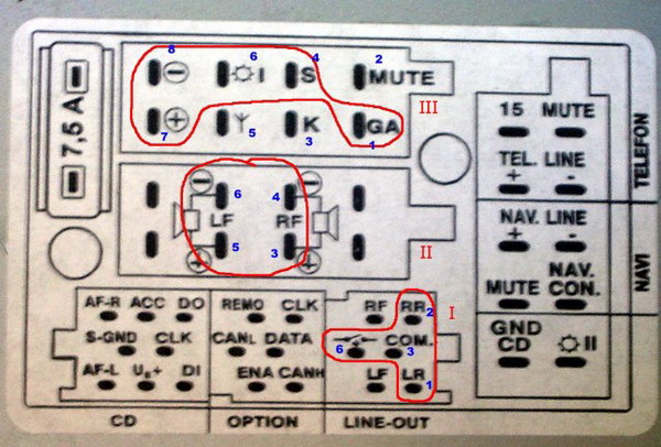
Here we use the AVIC line output to feed to the rear powered speakers
The reserve signal must be connected so that he AVIC knows when the vehicle is moving in reverse. The violet/white wire on the AVIC power harness must be connected to the blue/white wire on the brown connector using the provided crimp connector as shown on the following picture. This can be found behind the kick panel which is located on the driver side, left to the clutch pedal area. The panel is retained by two screws. The picture does not show the white strip on the blue wire, but it's there. If you are unsure use a voltmeter to find the wire that register +12V when the car is put into reverse (you can switch the key to on but not start the engine to test).  Since I didn't feel like hunting the parking brake wire down, I decided to implement the AVIC-D3 hack which permits all functions to be accessible even when the vehicle is moving. Obviously, use you own judgment when driving, keep your attention on the road. The hack can be found on this forum: http://www.avic411.com/forum/viewtopic.php?t=4670 Basically you will need to move the yellow/black (mute function) wire on the AVIC audio harness from the original location to an adjacent position as shown in the avic411 forum. Then ground this and the parking brake wire (light green wire on the AVIC power harness). The antenna amplifier is powered through the Metra antenna adaptor by connecting it to the blue wire on the AVIC power harness. The GPS antenna can be placed at various locations. I understand that GPS equipped Audis used to have the antenna on the rear deck nearby the right speaker. You can route it there if you want but for convenience, I opted to put the AVIC GPS antenna on the front dash as shown in this picture. The reception from the GPS satellites seems to be more than adequate. The antenna has a magnetic base and has to be placed atop a square metallic plate that is supplied by Pioneer. The antenna wire can be tucked between the dash and the bottom of the windshield. 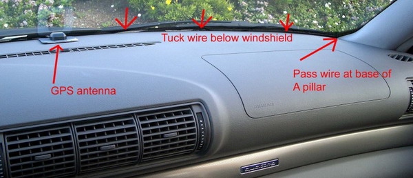 I fed the antenna wire through the base of the passenger A pillar and ran it above the glove box to the center consol. I used some the supplied adhesive wire holder to keep it in place and tied the extra length to the right of the glove box as shown below.  In the end you end up with a lot of wire that must be stuffed behind the Pioneer unit. Fortunately, there is sufficient room. The most difficult part for me was to mount the Pioneer unit in the spot where the Symphony radio occupied. You can use the Metra dash kit for this but I found that while the front plate does fit our car well, it does not fit the AVIC-D3 at all. There is an unacceptably large gap between the plastic trim piece and the screen. However, I did use the Metra mounting brackets that screw onto the side of the AVIC in order to provide support for the back of the unit. I shimmed the AVIC vertically by using some plastic pieces secured by double sided tape at the bottom as seen in this picture. The unit was then secured using custom L-brackets made from metal strips. I also used plastic pieces as spacer as seen in the following picture. There are some extra mounting holes on to the side of the AVIC for screwing the brackets. I took advantage of the two hex head screws that were nearby to secure the brackets to the center console. Adjusting the length of the L-brackets was by trial and error and took the most time.  Once the unit is secured, I took some measurements and fabricated a trim piece from 1/8” polycarbonate plastic I had. The main rough cuts were made using a hack saw, metal cutting blade work well. I recommend cutting the external sides first then cut the internal rectangular hole. I finished the edges using a file. Painting was a pain for me. I had to redo the paint job several times. Finally after the third attempt, I obtained the result I wanted. The steps are: 1) sand surface, very fine, wash & dry 2) thin primer coat 3) sand, very fine, extra fine, super fine to get good smooth surface, clean and dry 4) first coats of semi gloss black, very light layer, dry 5) light sanding, super fine, wash & dry 6) repeat steps 3-4 twice more, obviously don't sand after the final coat Letting dry for one day between each operation is critical to get a good finish. I also found that warming the spray can in some hot water helped provide a more uniform layer. The trim piece was attached to the center console by using some strong little rare earth magnets. The top magnet was secured by double sided tape, the bottom smaller ones simply stuck on the screw already present. On the trim piece I attached small blocks of ½” thick plastic onto which I taped holes which were later populated by #4-40 flat head steel screws. This allowed me to adjust the position of the trim plate to be flushed with the rest of the center console.  In the end, I am pleased with the unit. The navigation is very accurate and the sound from this system is significantly better than the stock radio. In addition, as you can see from above, custom background pictures can be uploaded to the unit from a CD-R. |
|
Advertising |
Contact Us |
Cookie Policy |
Privacy Statement |
Terms of Service |
Do Not Sell My Personal Information
© 2020 MH Sub I, LLC dba Internet Brands |