| Tech Article Title
|
Author
|
Date
|
| Heated Mirrors (Wiring to Rear Defrost Switch)
|
Stan Jirman
|
1999
|
Please note that all credits should go to Bob
Petruska who sent me the original instructions. Since this is really a simple thing to
do, not all steps are described. The description works fine on a 98.5 A4
with manual tranny and trip computer without any known side effects. I
have also tested it on my father's 98.5 Euro-specs A6Q with Tip and Trip - it works there,
too. Please note that you may have side effects if you have no trip computer - I didn't
try, but reported side effects include the loss of the temperature display and, with automatic transmission, loss of the gear selector display. If you want to make sure you have no side effects before getting yourself into the mods, pull #9 fuse (#9, not #6!!) and drive for a day or so. Check whether the mirrors stay cool and whether
everything else works. The 96 A4 does not need such modifications.
Note: An updated article has been written to deal with the loss of temperature/gear selector display. Click here.
You are performing this modification at your own risk.
 Required items: Required items:
- Common sense
- Soldering iron & solder
- Philips & flat screwdriver
- Metric socket ratchet
- One 30Amp car relay (Radio Shack)
- Some thick cable (14 gauge)
- Some thin cable
- Some female and spade connectors
- Electric isolation tape
- Cable binders
- Knowledge that 1" = 2.5cm
- Depending on skill and experience, about 1-2 hours of your time
FIRST, TURN OFF THE IGNITION.
|
Second, remove the
left knee bolster and fuse cover. The bolster is kept in place by 4 screws; be extremely careful when removing it - it is equipped with the diagnostic plug and a light. You must disconnect the cables leading to both items before removing it from the car. The pictures on this page will most likely have more cables than your car; this is because of my aftermarket radio, cell phone installation, and the headlight washer cutoff switch as described by Don Pavlik.
|
|
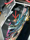
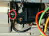
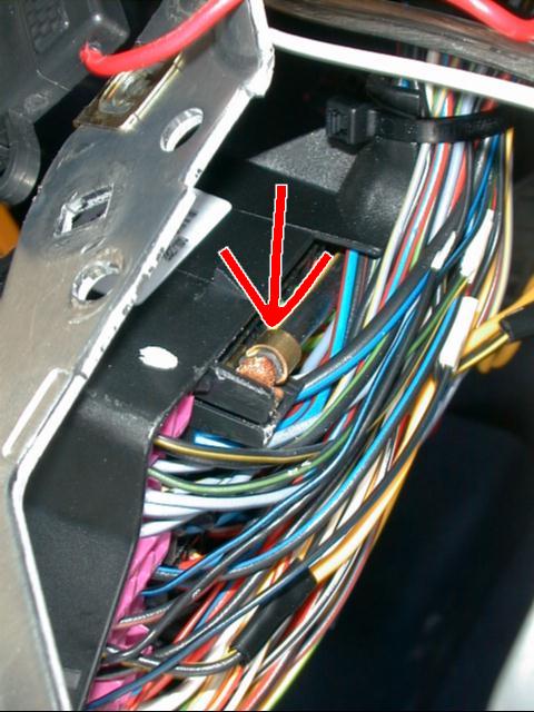
Also remove the lower left plastic cover at the feet. It has two screws, one of which is hidden behind a plastic cover which can be easily peeled off with a flat screwdriver. Then, loosen and remove the fuse box from its mount. Two metric screws are all you need to remove. Note that the screws which hold the fuse box are different that the four screws holding the knee bolster. Pull fuse box down and open it. Make
absolutely sure you have the ignition off, as if the main wire (arrow) touches the metal around the fuse box, you will shut down all of your car and will wish you never started this operation.
|

|
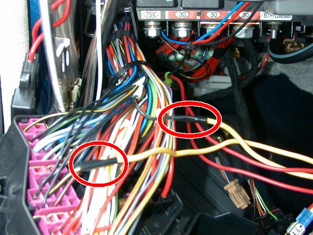
Now cut the wire that leads to the #9 fuse. While it's not extremely important which wire you cut, it is wiser to cut the black-with-red-stripe and not the black-with-white-stripe, because this way the fuse will protect the system in case the relay shorts out. I cut the wire about 5cm off the fuse so that I have enough space to handle soldering on both ends. This now divided wire will be operated by the relay. Create two thick cable snippets about 10cm long and attach a female connector to one end of each. Solder the other end of the 10cm wire to the cut fuse wire. Isolate the connections with isolation tape. That's about it for the fuse box part.
|
|
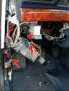
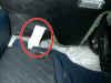
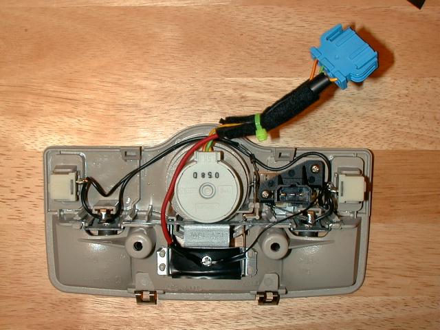
Next step is to locate the rear defroster cable. This one is at the very bottom blue connector at the driver's door, thick white cable. Before you cut or tap this wire, make sure we are talking the same wire: using your meter, measure the voltage by pushing one tip of the meter into the connector base and grounding the other one. It should be +12v if and only if the rear defroster is on (ignition must be on for this to work, remember above disclaimer). TURN IGNITION BACK OFF. Cut about 30cm of a thin wire and connect it to the defroster wire. I tapped the cable by melting some isolation with the soldering iron. After the solder cools down, make sure you have a good connection by wiggling the cable a bit and testing it with the meter. Use some isolator tape to isolate the connection.
|
|
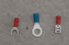
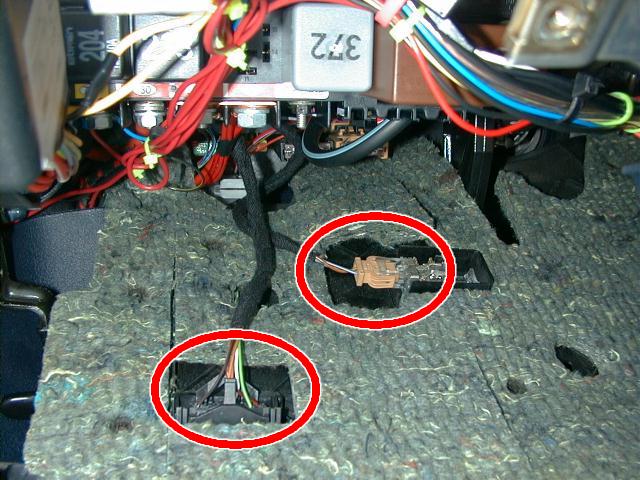
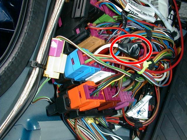
Last step is a grounding wire for the control circuit of the relay. Find a good place to tap ground (I did so by attaching a cable with a spade connector to one of the main ground screws right under the fuse box, same place where I took power for my cell phone kit, see picture). Now take some 20cm of the wire and attach a female connector to its other end.
|
|
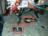
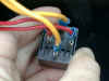
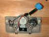
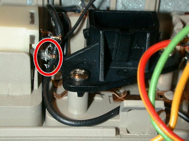
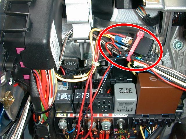
All we need to do now is to attach the four wires to the relay. Note the position of the relay pins - one is turned 90 degrees, which will help you with orientation. In the picture, the two thick yellow wires are the interrupted wire from the fuse box. It does not matter which thick wire goes where (up or down). The thinner red cables go to the other relay pins. It is important to understand that in the picture, the wire from Ground is the red wire with the blue connector, the one from the defroster grid is the red wire with red connector. It doesn't matter which colors you choose, but it must be the same wire to the same pin of the relay.
|
|
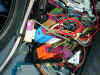
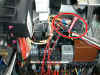
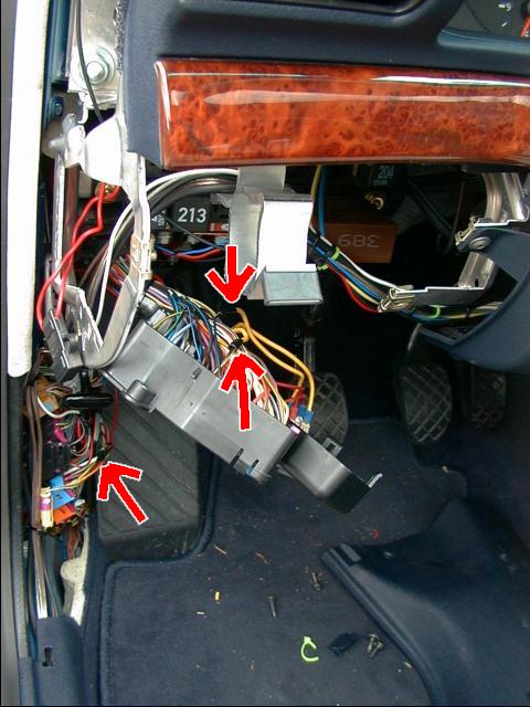
This picture shows all the things together, with arrows pointing at cut / attached cables. For testing, turn on the ignition. Hold the new relay in your hand. Turn the defroster on. You should feel a "click" as the relay switches power to the mirrors. Soon thereafter, the mirrors should be warming up. If you turn the defroster off, the relay will click again and interrupt the circuit. Make sure there is a 10A fuse in the #9 slot. TURN IGNITION BACK OFF.
|
|
That's it. Clean up everything with cable binders. I have more cables around, you will see less than on this picture.
|
|
Close up everything. Watch out for rattles: the fuse box is kinda obnoxious for making noises if not properly attached - I am speaking from experience :-) When putting the knee bolster back, please make sure that it is held properly in place: there are clips where it will slide into. There is another clip at the right bottom screw - make sure you get that one, too.
|
|
This is it - now we have the mirrors operated by the rear defroster switch!
|
|


