|
|
Adjustable Temperature Soldering Iron No. 10 Torx Driver ChipQuik Desoldering kit Jewelers Lupe 3M Blue Tape Small Flat Head Screw Driver 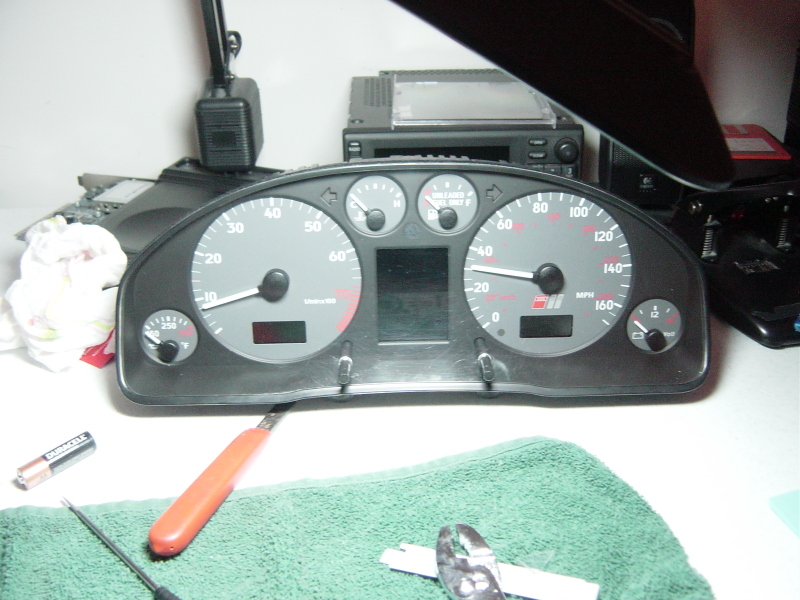 Well for the last 7 years I have had to live with the inherent failure (loss of pixels) with the LED back lit LCD display in my 2000 S4 instrument cluster. This DIY will try and provide some general guidelines, tips and suggestions to install a new LCD screen. Be advised I will not be held responsible for any damage you may cause to your cluster by following this guideline. Perform at your own risk. I purchased my new display off EBay from a seller in the Netherlands. I paid $115.00 for mine but it turned out to be a genuine VDO display and not a cheap replacement from china. The color matched the original perfectly. First off you need to remove your cluster the vehicle. There are plenty of DIY's out there showing you how to do this. I used the one provided on Stratmospere: http://www.stratmosphere.com/OCT_S4_BoostGauge_Strat.pdf No need to remove any of the lower panels shown in these instructions just start at figure No.6 remove the black trim piece and unscrew the screws and wiggle out the cluster then undo the 3 rear connectors. Follow the instructions to pull apart the cluster. You don't need anything special for the clip shims. I just broke up an old CD jewel case and made some shims. Once you get it apart I simply followed the above procedure to remove the pointers and dials. One hint is use some blue 3m tape on the dials when prying off the pointers so you don't scratch it up. Also I took a picture of the dials to have a reference for the pointer positions. You don't want to remove the temp and volt dials or pointers. I will say the hardest part of this entire repair was getting the pointers back to the correct positions. I strongly suggest once you are done don't snap the cluster housing and the front cover together. First install the unit less the front cover and start the car. I had to do this about 4 times each time removing and reinstalling the speed and tach pointers until I could get them back to zero. Ok now that you have the cluster cover and dials removed you need to remove the white plastic dial holders. As directed above you didn't remove the temp and voltage dials or pointers but in order to remove the large white plastic dial holders you will need to cut the big dial holders free of the smaller holders. See below: 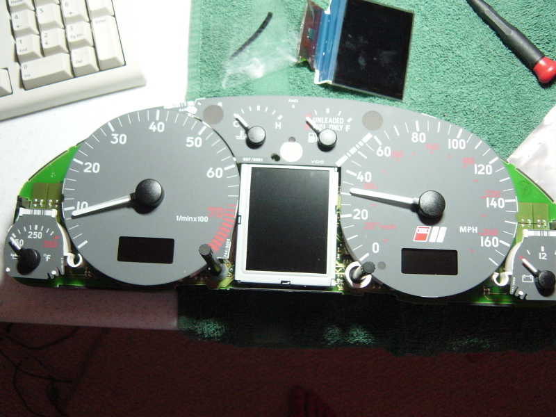 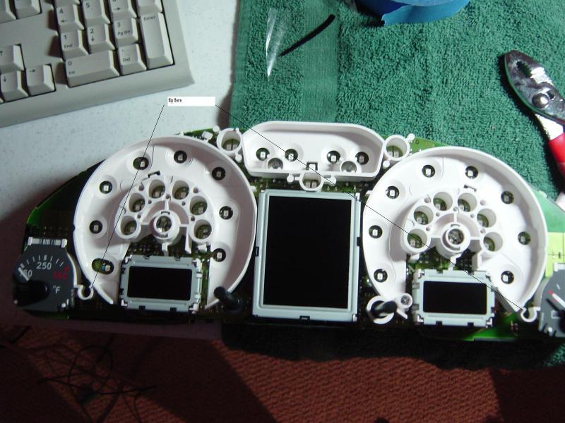 Now with the dial holders nipped you can remove them by flipping over the board and bending the metal clips holding the milage and clock LCD's and pushing the white plastic clips out: 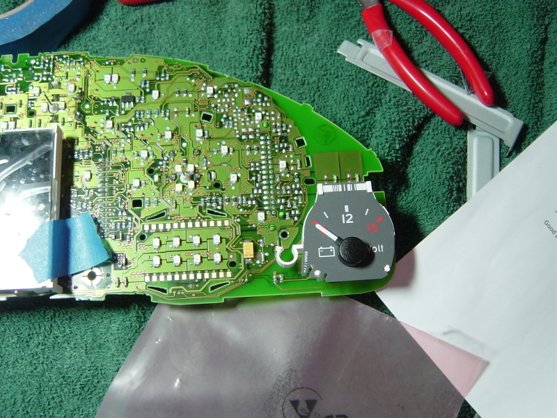 With the dial holders removed the last thing you need to remove is the metal LCD screen holder. Again just flip over the board and bend the metal tabs and it will pop out. 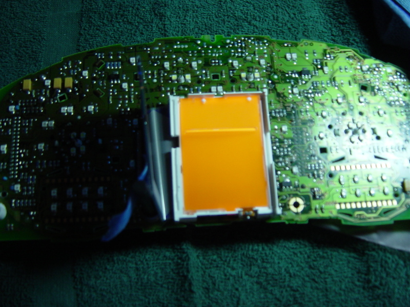 At this point removed the orange rear reflector and set it aside so I wouldn't damage it. Now its time to remove the old display. 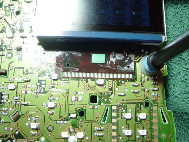 You need to simply take your soldering iron and melt some ChipQuik SMD Rework solder across all the pins in the ribbon cable. Make one elongated pool of solder across all the pins http://www.chipquik.com/smd1.htm 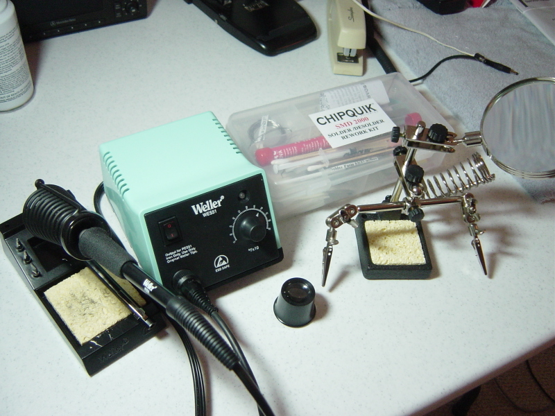 This rework solder has a very low melting temperature and will stay liquid much longer than regular solder and keep the original solder liquid as well. The old display will simply come right off. I kept my Weller WES51 at around 650 degrees F seemed to work fine. 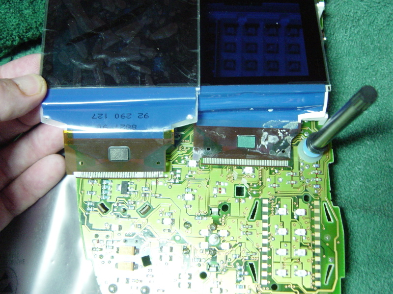 Now you need to remove any ChipQuik from the pads. Just follow the directions with that came with the kit. Its important to clean it well. Then you need to use a jewelers lupe or large magnifying glass and tin each pad with a bit of solder. Some paste flux really works well here to insure you don't bridge any pads. Once all the pads are tinned line up the new displays cable over the tinned pads. When you can't see any pads you know you are lined up perfectly. I used some 3M blue tape to hold it in place. The simply hit each contact on the cable with your soldering iron. Don't hold it to long the contacts can detach from the ribbon if heated for too long. Once all the contacts are soldered to the pads you are good to go. 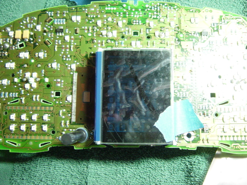 Now simply reverse the steps above and put it all back together. Remember don't snap the front protective cover on the display until you connect the display to the car to make sure your pointers are lines up. Here you go looks like new. 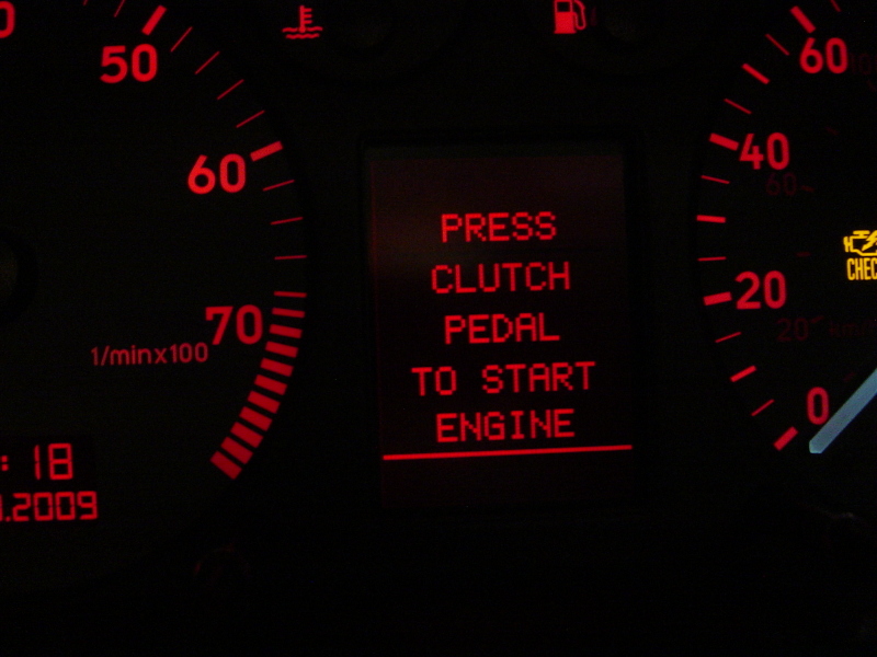 Thanks to everyone for the help and pointers. Especially MacGyver who really gave me some great advice. Hope this helps! |
|
Advertising |
Contact Us |
Cookie Policy |
Privacy Statement |
Terms of Service |
Do Not Sell My Personal Information
© 2020 MH Sub I, LLC dba Internet Brands |