Introduction
Many of us, myself included, have spent a sizeable sum of money in the pursuit of the perfect Audi. For most this pursuit is satisfied by simply chipping the car or maybe installing an sport exhaust, but regardless of how well tuned you car may or may not be it's all for moot if the car is unreliable.
As many of you well know the turbo has a pretty tough life -- even more so in a chipped car. If you've never seen what your turbo looks like after spirited driving maybe you should make a point of checking it out. It's alarming to say the least.
Unfortunately the only way to ensure the turbo is given a proper cool down is to either drive like a candy ass for the last few miles of your trip or idle for a minute or two once you reach your destination. Both of the aforementioned techniques are fairly effective, even more so when combined. By no means particularly convenient especially when you're pressed for time.
After a full year of religiously waiting for my car to idle down every time I drove somewhere (all the while being harassed by my co-workers for making them wait at lunch and such) I decided that I needed a turbo timer. The only problem is that the turbo timer would interfere with the operation of the factory alarm system, or at least so I thought. Over the course of the year I waited in hopes that someone would provide the holy grail so to speak: a diagram which would show us the way to enlightenment (yes a turbo timer that works with the factory alarm). But alas it never materialized.
I decided to take matters into my own hands and with the help of a few people (phone calls) and a few hours of digging through my dash I've successfully installed a turbo timer with factory alarm support. The key components were data collected by sticking needles through wires and reading out their functions with a DMM (Digital Multimeter) and ultimately a wiring diagram (sketchy lacking detail and legibility) but immanently helpful from HKS. I'm writing this FAQ in the interests of taking all of the guess work out of the operation. I wasted one weekend on a failed attempt -- and succeeded on the second attempt -- with this document in hand I can virtually guarantee that you'll succeed on your first try.
Tools that will be needed:
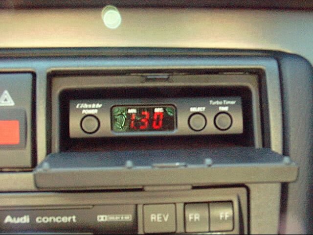
- Greddy Turbo Timer III (~$80.00)
- Soldering Iron
- Solder (non-acid core)
- Torx Screwdriver T10 if my memory serves me.
- Wrench or ratchet / socket (for battery terminals)
- X-Acto knife
- Wire Cutters
- Friction Tape (it's highly advisable to use friction tape...I'll explain later. BTW - this is very similar to the tape which is used on hockey sticks...you can buy it from any Sporting Goods store)
- Nylon Webbed Loom
- 14ga. Red Wire (Stranded not solid core)
- 14ga. Black Wire (Stranded not solid core)
- 22ga. Red Wire (Stranded not solid core)
- Asst. Heat Shrink Tubing
- Lighter for Shrink Tubing
- Multimeter (Optional)
Instructions
First begin by disconnecting the negative terminal of your battery. This is to ensure your safety and the integrity of your wiring harness should you happen to short something out while you're cutting or soldering.
Back inside the vehicle remove the trim piece directly above the steering column -- it's between the steering wheel and the instrument cluster. This piece simply snaps out by pulling the top towards your chest if you're sitting the drivers seat. Once this piece is removed you'll see two Torx screws which you should remove and set aside.
Release the adjustment lever on your steering column and pull it fully towards yourself, then down as far as it will go. Re-lock the column.
Gently pull out the cluster (only two screws hold it in) starting with the left side rotate the cluster (in your left-hand) counter clockwise by 90 degrees. You should see a purple or pink multi-pin connector remove it by operating the lever, which is built into the connector. Pull the cluster further towards you. You'll notice another connector around the middle of the cluster towards the bottom, remove it by squeezing and pulling simultaneously. One or two more connectors (depends on trip computer I think) to go (in my case the last one was on the far end near the voltmeter). Remove this one like the first connector -- it's lever operated as well.
Your cluster should be free now. Set it in a safe place cause if it breaks it'll set you back a handsome sum (approximately $400+ US).
Now move the steering wheel to its full inward and upward position, then lock.
Remove the lower knee bolster -- there are 4 screws total two of which are hiding under those rectangular covers (remove carefully by wedging with a sharp knife). Remove both of the hidden screws, then there is another down low near the gas pedal. Finally there is one inside the fuse box on the drivers side. At this point the bolster should be able to slide towards you, but be careful as your VAG OBDII port and foot-well light are still attached. Remove both connectors and set them aside. Sme for the bolster.
With the bolster removed you can see the wonderful world of Audi wiring; it's a spectacle the first time you see it. On your left you'll see the backside of the fuse box. Pop the rear cover of the fuse box off and set it aside.
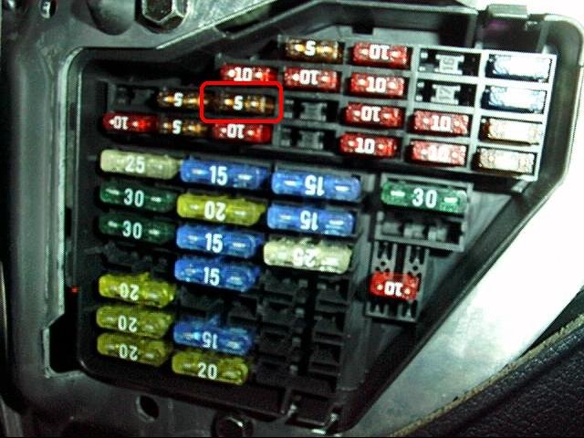
 From the front of the fuse box locate fuse number 6 as highlighted (red box) in the picture below. It will be a small 5 amp cartridge type fuse, probably brown in color.
With the back cover of the fuse box removed locate the 22ga. Black/Blue wire which is connected to the rightmost blade of the fuse (facing box as in picture) or leftmost side of the fuse as seen from the backside of the box. It's honestly pretty hard to miss as one side of the fuse blade is attached to a buss-bar, which is integrated into the fuse box and the other end is attached to the wire you want. In the case of my car the wire also had the designation A6 printed in white on it, I think you'll find the same true for yours, but I make no guarantees.
Once you've located the wire described above cut it about 2 inches from the fuse box (so it can be put back to stock if you ever decide to). Tape off the end still attached to the fuse box -- you're interested in the end, which came out of the wiring harness leading into the fuse box.
Below I've included a wiring diagram depiction of the process described above. The area with the circle is where you will cut; just do as the instructions on the picture indicate.
Ok now it's time to move on to the key switch work; unfortunately it's impossible to gain direct access to the key switch w/o removing the steering wheel so you'll have to do it up top. This is why I had you remove the instrument cluster.
I've attached above the schematic for the key switch just in case you feel more comfortable having a copy while doing this kind of surgery on your car.
Staring into the gaping hole your cluster once occupied you hould find a fairly thick harness which comes up from the left side of the steering column. It's encased in a nylon webbing and then wrapped top and bottom with friction tape. It's in this mess of wires that you'll find the two you need to pull this thing off.
Carefully cut away the friction tape so that the wires are exposed and easily to manipulate -- always give your self plenty of room to work. You don't want to go melting a bunch of wires with your soldering iron just because the others were jammed up against the ones you were working with.
As I mentioned before it really helps to have the steering wheel all the way in and up. This creates the maximum slack in the harness giving you more room to work.
Locate the large 10ga Black wire which is the ignition line (not starter) needed to make the turbo timer work. Carefully using a razor knife scrape away the insulation off a 1/4 inch section of the wire (I don't suggest cutting...just remove the insulation) tin this segment with your soldering iron. Attach the Green Turbo timer wire here by wrapping the bare wire around the tinned black wire, flow some solder over the wire and carefully wrap up the connection with friction tape or similar. I can't stress enough how important it is to keep all your work as compact as possible otherwise believe it or not you'll have trouble getting the cluster to sit in the dash correctly.
Now locate the 14ga red wire which comes up from the ignition switch. This is your 12 Volt constant which is used to power the turbo timer. You may become confused, as there are several red wires in that bundle. If you like you can remove the upper trim pieces on the steering column and loosen the lower piece as much as possible (Allen screw underneath lock lever, and two Phillips screws up inside the holes on the bottom side as well). With all of these things loose you can just barely look at the back of the key switch. You'll see 5 positions on the switch and a total of 6 wires; one of the switch positions is shared with another wire for the Load Reduction Relay just FYI. Anyhow you should locate the red 14ga wire which comes out of the ignition switch (you can pull on wires up top and see if they're moving below); this is a good indication that you've got the wire you want.
Once you're sure you've got the right 14ga Red wire splice into it as described above and attach the Red wire of the turbo timer here.
Now locate the 22ga red wire, which also comes from behind the ignition switch. This is the key warning line. Expose the wire as described above, but this time splice a sizeable length of 22ga wire which is long enough to reach the little blue wire you cut down by the fuse box. Personally I think it's best to give your self way too much wire, get it all taped into place and solder it up. There's nothing worse than coming up short on wiring harnesses. OK now that you've got your length of 22ga Red wire spliced in and neatly routed around your dash, attach the other end of that wire to the end of the blue / black 22ga wire which you pulled from the fuse box. Twist and solder them together, then tape or shrink tube them up and tuck away neatly. Remember I'm referring to the side which is not attached to the fuse box. There should be a short length of wire still attached to the fuse box and nothing else. Just tape that little stub up and set it aside.
Put the cover back on the fuse box (behind)
Locate a decent grounding point on the chassis of the vehicle to attach the one remaining turbo timer wire to (black ground wire with lug crimped onto it). Might I suggest that you consider (depends on mounting location) the bolt which holds one of the knee bolster mounting brackets in place it's on the right side, say transmission tunnel area I guess you could call it. This is where I attached mine...works fine for me.
FYI - the Blue turbo timer wire will NOT be used in this installation. You can simply cut it off or wrap it up behind the timer, just be sure to insulate the free wire end.
Once all is said and done re-tape the wiring loom behind the cluster with the friction tape you purchased, you did purchase friction tape didn't you? I swear you're gonna be hating life if you tape it back up with electrical tape because it will squeak against the back of the instrument cluster; it nearly drove me mad. Friction tape is the key to a quiet dash; it's worth the $2.00 investment.
If you're feeling bold now would be a good time to re-attach the ground on your battery. Watch out for smoke in the dash -- this would be a sure sign of a serious wiring error. Allow the car to sit for a few minutes with the battery re-attached and the key-switch in the on (not start) position so that the throttle body adaptation can take place. Do not immediately start the car. Upon turning the key to the on position you should hear a little
song; this is a good indication that you've got power and more likely than not the timer is going to function. Note: The music can be disabled, the instructions are found in the documentation which accompanies your Greddy timer.
Now would be a good time to disable the e-brake feature if you didn't wire the car up for it, otherwise if you leave it enabled the car will turn off immediately when you take the key out because it thinks the e-brake is down. The turbo timer manual explains this process clearly. If you want to wire up the e-brake feature simply follow the instructions provided with the timer.
Once you're confident that you have the timer properly set up feel free to start the car. Allow it to run for a moment then turn the key to off. If all was wired properly your car should continue to run and the timer should be counting down. At the end of the cycle the engine should die.
It's been my experience that you can arm the alarm at any time during or after the count down, try it for yourself. Well I'd say that pretty much sums it up. Re-assemble your car and enjoy your newfound level of convenience.
Final Notes / Warnings / Pics of my Install
First of all, I hate to do this but...
Disclaimer: I assume no liability or responsibility for any damages that may arise either directly or indirectly as a result of the application of the information provided herein. Please read instructions fully before attempting this modification.
OK enough of that...there are a few things to note about having a turbo timer. First of all I think it's pretty obvious but I'm going to mention it anyway -- since you are leaving the car to idle you'll have to leave the car in neutral and this is a potentially bad idea, especially when you're parked on a hill. Be sure to always turn your wheels in or out depending on the slope. Secondly, since you're in neutral the car could potentially be easier to tow away. I always lock my wheels to one side; this way it's hard to put the tow rig on (if not impossible). Anyone can cut the e-brake cables, but it's not too easy to straighten the steering out when it's at full lock. Be careful parking in your garage. Carbon monoxide poisoning is a very real concern, and I'm not referring to just yourself. It could be your child who's the car while you're grabbing your groceries or your pets if they live / sleep in the garage etc.
Finally, engine wise everything seems to be cool. I can't think of any problems that this could cause other than maybe an unattended engine fire occurring.
One thing I did notice though is that it causes the climate control to throw DTC's. Basically what happens is some parts of the car are still receiving power yet others are not. In the case of the climate control system the climate control computer is still running, but there is no power getting to the HVAC fan motor. Well the problem is that the HVAC fan has a speed sensor on it -- the car uses this data to adjust fan speed etc. If you leave the climate control on with the key out, the computer gets confused because it's telling the fan to spin at "X" RPM, but in reality it's not spinning at all because it has no power. It's actually kind of funny to watch when the climate control gets pissed and tries to ramp the fan up to full speed. It does this a few times and then you can see it give up. I'm pretty certain this is entirely harmless and I've decided to live with it. You'd never even know it was a problem unless you had a scan tool like Vwtool which I used to detect these codes. You can get around this by religiously lowering the fan speed till it's off before you take out your keys, but why bother if it doesn't hurt anything. Ultimately I'm sure this could be fixed by keeping the appropriate line hot, but which one I don't know. I'll have to look into to it and maybe I'll issue a FAQ update when I figure it out.