| Tech Article Title
|
Author
|
Date
|
| A6
Door Contact Sensor Repair |
laasby
|
2004 |
After a 1 hour disassembly, 4 hour understanding, 1 hour fixing, 2 hour assembly, the door contact sensor is repaired. You probably would use 2-3 hours using this
explanation. I did it on another car later, and used 2 hours (the full fix).
I've seen a lot of posts regarding this problem, so it seems like a quite common problem. I'm posting my repair notes since this
aint covered in any manuals I've read (I'm a Bentley Pub customer). A new latch is quite expensive, and quite irritating when not working, so I decided to find out and fix
what's wrong.
My Car : 1999 A6 Quattro 2.4 litre european ver.
The problem is not the sensor itself, either the mechanism that triggers the sensor. It's the contact between the circuit board and the plastic connector, oh well, in my case. The circuit board also contained
a lot of corrosion. The core problem is that the electrical box is not 100% water proof - and damp will find its way into the box.
There is an quick fix for this, if your ONLY problem is the door contact sensor, and not anything else (central locking etc..)
Here goes the full fix :
---------------------------------------
You'll need :
- a torx set (10, 20 and 45)
- M8 bit (for the latch - do not use a torx here!)
- Solder equipment
- fluke or equiv.
- CRC electric cleaners (or equiv).
- (optional : some calming medicine when you try to reattach springs :-) )..
Difficulty :
- Medium
Pre-req :
- Time
- Understanding of basic electrics, and ability to solder. Your problem might not be exactly where mine was, but you should find out..
Started out by removing trim, and hoped to remove the latch without removing the window mount. It's says so in the
Bentley, but it was too tight. Removed window mount, and it was easier to flip off the connector, key rod and lock rod.

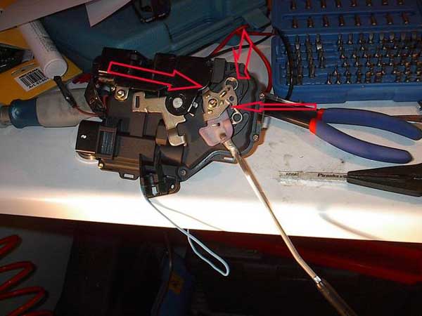
The blue rings shows two M8 screws that actually holds the latch. Flip off the plastic that hold the lock rod. Pull that rod off. Then the key rod. You'll have to wiggle that out (pull a bit down and turn clockwise, it just holds by the rods length).
The red-ring on the right site has two pop-off connectors, the left side has one pop-off that has a screw (that you'll have to remove first).
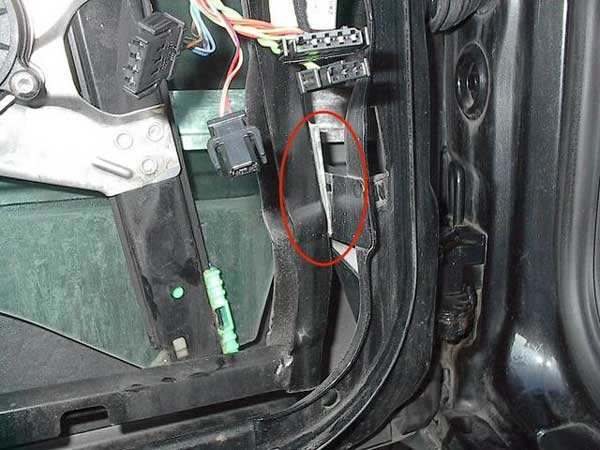
I took of the window mount, just because I got more room. Remember how it was mounted.. Would be easier to remount. The prev pic showed 4 green rings. Torx 45. When remounting, you should fasten the upper two before the torx on the bottom (work right to left)
Took off the latch, and went to the workbench. Started with the sensor, a bit greasy on the outside, but opening it up, it worked perfectly. No corrosion - clean metal. Measured with diode settings on a fluke.
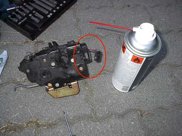
First I tried just to clean it.. thought is WAS the sensor..
The red ring shows the metallic clamp that holds the sensor to the latch. Just flips off.
Then checked the latch mechanism that activates the sensor - checked also out OK.
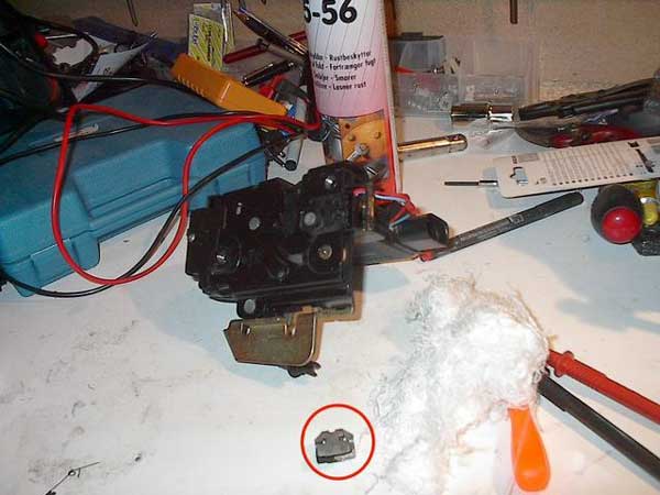
Then I had to open the box. It's actually two parts. One with the mechanism that locks the door in place, and one electrical part with the small electric engines that drives the locking system.

This was a tricky job, first off I saw 2 springs connecting the locking mechanism. Split the two parts (2 torx-20 + 1 torx-10 and two plastic locks) and open the box containing the circuit board (6-7 torx-10).
OPEN THE BOX CAREFULLY.. This box contains a lot of loose parts, and if you open it the wrong way, they all fall out of their respective places. You'll then have to play the game of "What did the engineer think". I did the wrong way, and played that game..
(See below under assembly).
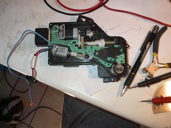
I've got an old "low voltage" degree, and I'm amazed that this thing still had some functions that worked.. Corrosion on the circuit board, in almost every line. Well, after some troubleshooting, all the lines checked out OK, but the 10-pin connector to the circuit board. Line 3 and 5 were corroded off. Missing 2 cm from circuit board to the plastic connector (!).

Here's the circuit board. The rings shows where most of the corrosion where. On the thin electric lines and down by the connector (on the other side - se pic below).

Ugh.. bad pic, but you see the corrosion. When the latch is installed, this is the absolute bottom of the box - and when the box is not tight, water/damp concentrates here..
Rewire those two missing lines with some 0,25 wire. Since I didn't trust the remaining lines connector, I've soldered new lines from the circuit board and made my own connector. Made a new hole in the box and used silicone to keep the damp out.
You can do two things her, either solder a complete new connector system, or just
solider those lines that were broken. If you to the latter, you'll also have to make holes in the box (as mentioned).

I soldered from the upside of the board.

The orange ring around plastic arm has to be refitted when the circuit board is in place. The "arm" of this, will touch the
micro switches on the downside - left of the circuit board. The micro switch I'm talking about is about where the green ring is, when you've reattached the circuit board.
I used 1 hour to figure this out!! ;-) Didn't remember where that plastic thing has it's place..
The reassembly of the box might require valium.. Check out that all the motors, gears and plastic rods are functioning before closing the electrical box. Push and pull the rods and see to it that the gears and motor are rotating. The grey motor drives the mechanism that locks the other motor.
The reassembly of the two main parts where probably the worst. The springs that actually lock the door where a bit of a pain. Here I've took some pics of which
method I found out to be easiest.
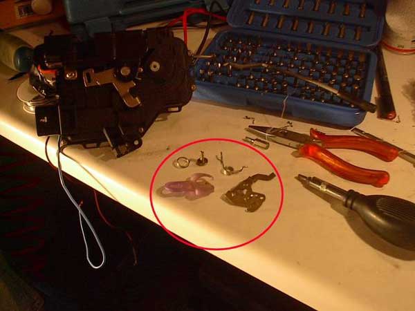
The four parts left after you've put the two main parts together (all the torx)
You'll then have 4 remaining parts - 2 springs, one plastic and one metal arm. (and one screw of course).

Get the metal arm in the hole you can barely see within the box (use a flashlight if you can't see it). Its a horseshoe that it will fit into. It's a PITA to see in there, but you'll find out with the right lighting.

You'll have to wiggle a a bit to get this arm right, and I had to set the torx screw just inside, so I could pull out the white rod that the metallic/plastic arms are connected to. You'll figure it out! Don't screw tight before you see that the white rod are lined up with the white arm.

Then it should look like this. Attach the two springs. The biggest will fit at the upper arrow. The lower spring fits within the hole at the lower arrow and in the only little hole in the box (you'll see it).
You're done! Here you'll see where the springs are connected.

Reattach the latch and hot-wire the new connectors you made into the wires from the car. For my experience, I had to make new connectors for line 4 and 6.
At last the car warns me that the light is on when I try to exit the car. No more flat battery! ;-)
For a workshop I understand why they replace the whole latch.. You'll need the original connector parts to repair this the right way, and the labor will cost more that replacing the part.
The Quick Fix :
--------------------------------------------
You will only need to remove the trim for this. (two screws on the left and right side, high up). Slide the trim upward and disconnect all the connectors and the wire (for opening the door)
As mentioned, if your only error is the door contact sensor, you can override the error by connecting the blue wire from the sensor (under the latch) to line 4 on the wireset (from the car). Make a hole in wire 4 (on my car : yellow/light green color) measure it with a fluke to pin 8 on the latch/connector. I use the diode setting on the fluke, so it beeps when there are connection.
If this works, you can do this fix! Just cut off the blue sensor wire and solder
it to wire 4 (there are numbers on the connector). See the previous picture. If the connector is connected to the latch, you'll see lights in the car! YEAH!
GOOD LUCK!
Thanks goes to fast928 in the forum over at Bentley Pub.
|