| Tech Article Title | Author | Date |
| Diagnosing Oxygen Sensor Heater Codes | Shard7 | 2007 |
Modern oxygen sensors include an electric heating element, and as one might expect, a failure of the heating element can result in various diagnostic trouble codes and an illuminated Check Engine Light. On an Audi, the design of the ECU results in ambiguous trouble codes when a sensor's heating element fails, and extra diagnostic steps are needed to determine which sensor is actually faulty. This article explains how oxygen sensor heaters work, how failures are detected, and how to correctly identify the sensor in need of replacement.
Why Do Oxygen Sensors Have Heaters?
An oxygen sensor needs to be at a temperature of around 600 degrees Fahrenheit in order to function, so immediately after a cold start it cannot provide any useful information for controlling the fuel mixture. Hot exhaust gases naturally heat the sensor to its operating temperature within a few minutes, but during that time the fuel mixture won't be optimal and the exhaust gases contain higher levels of pollutants.
To solve this problem, the modern oxygen sensor includes an internal electric heating element. The heating element is switched on by the ECU when the car is first started and remains on as needed to keep the sensor at the correct operating temperature. With this capability, the sensor can be heated up much faster and the fuel mixture can be optimized less than 30 seconds after a cold start.
What Happens When They Fail?
A failure usually occurs when the heating element burns out due to age or shock or the sensor's wiring harness becomes damaged. To detect when such failures occur, the ECU monitors the amount of current drawn by the heater when it's in use; if the current drops below an acceptable level (i.e. the resistance is higher than it should be), it is assumed that the sensor has failed. Sounds simple enough, right?
Unfortunately, it's a little more complicated on an Audi because the ECU uses a single circuit to control and monitor both the pre-cat (S1) and post-cat (S2) sensor heaters on a given cylinder bank. As a result, the ECU can only monitor the combined current draw of both of the sensors. Since it knows what the current draw should be for both heating elements, the ECU can still detect when one sensor fails because the current draw will be roughly half of its normal value. However, the ECU cannot determine which of the two sensors (S1 or S2) is malfunctioning, so to reflect its ignorance it generates the appropriate trouble codes for both sensors.
The following trouble codes may appear if an oxygen sensor heater failure occurs; they will usually appear in pairs with the same error reported for both Sensor 1 and Sensor 2 on the same bank:
| P0135 | O2 Sensor Heater Circ.,Bank1-Sensor1 Malfunction |
| P0141 | O2 Sensor Heater Circ.,Bank1-Sensor2 Malfunction |
| P0155 | O2 Sensor Heater Circ.,Bank2-Sensor1 Malfunction |
| P0161 | O2 Sensor Heater Circ.,Bank2-Sensor2 Malfunction |
| P1116 | O2 Sensor Heater Circ.,Bank1-Sensor1 Open |
| P1118 | O2 Sensor Heater Circ.,Bank1-Sensor2 Open |
| P1120 | O2 Sensor Heater Circ.,Bank2-Sensor1 Open |
| P1122 | O2 Sensor Heater Circ.,Bank2-Sensor2 Open |
| P1196 | O2 Sensor Heater Circ.,Bank1-Sensor1 Electrical Malfunction |
| P1197 | O2 Sensor Heater Circ.,Bank2-Sensor1 Electrical Malfunction |
| P1198 | O2 Sensor Heater Circ.,Bank1-Sensor2 Electrical Malfunction |
| P1199 | O2 Sensor Heater Circ.,Bank2-Sensor2 Electrical Malfunction |
Which Sensor Is Defective?
When heater-related codes appear for two sensors, our natural inclination is to assume that both sensors have failed. However, the ECU is really indicating a failure in either of the two sensors, and chances are that only one sensor has actually failed. Fortunately, it's quite easy to test each sensor individually with a multimeter and determine which one is actually defective.
A sensor is located before and after the catalytic converter for each bank of cylinders, so 4-cylinder engines have two sensors whereas V6 and V8 engines have four. If the engine is a V6 or V8, the diagnostic codes will indicate whether the problem is associated with bank 1 or bank 2, and only that bank's sensors need to be checked.
The connectors on the B5 A4 are located on the firewall behind the engine and use the following color code (consult a repair manual for the connector colors and locations on other models):
| 4-Cylinder Engines | Pre-cat sensor (B1 S1) | |
| Post-cat sensor (B1 S2) |
| 6-Cylinder Engines | Bank 1 (Passenger Side) | Bank 2 (Driver Side) |
| Pre-cat sensor (B1 S1) | Pre-cat sensor (B2 S1) | |
| Post-cat sensor (B1 S2) |
Post-cat sensor (B2 S2) |
With the engine off, separate the connector for the suspected sensor (squeeze the latch tabs on both sides and pull it apart).

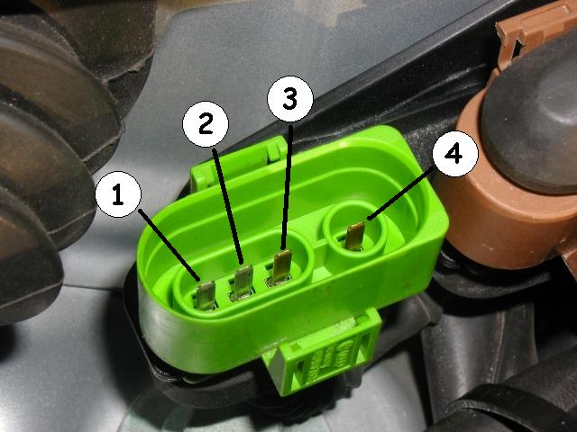
The side with the pins is connected to sensor, and the other side is wired to the ECU.

Locate pins 1 and 2 on the sensor side of the connector (these pins are wired to the sensor's heating element, pins 3 and 4 are used for the sensor's oxygen level signal).

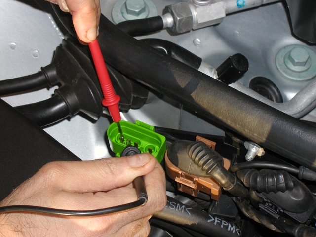
Set the multimeter to read resistance (ohms) and measure between pins 1 and 2.

A reading below 20 ohms (as shown in the photo) indicates that the sensor heater is okay. However, a reading of 20 ohms or more (usually a lot more) indicates that the sensor is defective and needs to be replaced.
