|
|
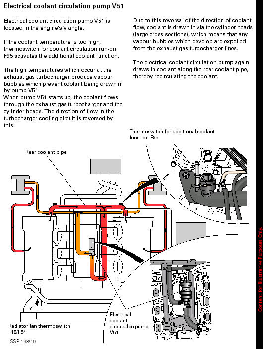
Not responsible for fried parts, delusions of success, cold pizza, flat beer, or boring friday nights. One of the first things I added to my S4 was the Mach V digital boost gauge. This is a really trick unit- it's a HEADS UP DISPLAY! No A-Pillar mount necessary. Check it out, I highly recommend it and it's been very reliable thus far. Integrated into it is a turbo timer. What's neat about this particular timer is that it pays attention to how much boost you've been using, and how recently (of course it knows since it's your boost gauge) .. and will vary the amount of time it idles your engine based on how hot it estimates things are.. You can adjust the curves and levels, or just stick in a default amount, say.. 2 minutes. That's what I ran for about 10 months. There are some severe drawbacks to this, as you are effectively leaving your car out of gear and relying purely on your emergency brake. This is not kosher in the hills of San Francisco even with the wheels curbed. Furthermore, you're /idling/ your engine. Yeah, that cools the turbos down.. but.. it also heat soaks everything under the hood.. Well, /WHY/ not take advantage of your S4tt's built in after-run coolant pump circuitry? "Woah, hold on there.. afterrun pump.. what is that?" Audi engineers are very smart, and they plumbed in a small reverse-flow electric coolant pump to cool the turbos AND push any possible air/steam created in the turbocharger waterjacket into the transparent plastic coolant reservoir. Additionally, it runs the electric pusher fan and the electric puller fan at approx. 40% duty cycle for up to 10 minutes-- all of this after the engine is turned off. You may or may not have ever heard this neat little system turn on. The reason why is the thermostat for it is set to something very, very high. I don't have the details but my guess is it's set to 240 degrees F. Unfortunately, the measured coolant temperature is not directly related to turbocharger temperature. A slight oversight on Audi's behalf, but it would cost a considerable amount to measure the turbos temperature more accurately. Want proof? Get in your S4. Drive it hard (oh the agony and suffering there) and let everything get completely to operating temps. It doesn't matter how hot or cold it is outside. Make sure to use a lot of boost right before pulling into a parking lot. There, idle it for 2 minutes (simulating if you had a turbo timer or were physically sitting in the car waiting), and then turn the engine off. Turn the ignition back on 10 minutes later. WOAH look at that temperature gauge! It's way above normal. Yet your afterrun pump is just sitting there, quietly saying "Run me! Run me!" .. completely inactive. Unless it's REALLY hot out, and you've been getting on it for an extended period of time (like.. say.. at Laguna Seca or Thunderhill) it's probably not running when you turn your engine off. Well, read below and you can make it run when you want it to... your turbos may thank you for it down the road, and never again will you have to sit in your car feeling like an idiot while your friends are all staring at you wondering why it is you won't join them walking into the restaurant you all just parked at. "He's letting his /turbos/ cool down..." they all say to each other thick with quasi-serious sarcasm. First things first. You need to install this turbo timer exactly like you would a Greddy III unit. If your turbo timer is already installed, you need to be fairly well versed with it to perform this modification. For MachV installs- chop the big 3 wire connector off and you're left with three main wires. Unfortunately the MachV headsup gauge comes with essentially zero instructions telling you what the Blue, Red, and Green wires do. Lucky you, I've figured it out already-- I had to dissect my unit and trace the wires back to make sure I wouldn't fry it the first time I hooked it up. And good thing, too.. as I assumed the blue wire was the ground. The blue wire is not needed, it's a secondary power output. Red gets spliced to a Constant 12V+ source. Green gets spliced to your Black ignition wire. Ground is obtained via the boost gauge portion. The hyperlink above shows how to find these wires and hook up to them. Be VERY careful. Since this is integrated with a boost gauge, also install it like you would a boost gauge. Even if you aren't very careful, you won't have any problems unless you're an idiot and cut through the entire wiring harness on accident. (!!!) Yes, yes.. I did. The harness behind the gauges has a nylon sheath around it.. I got creative with tin snips, and hacked through almost all the wires in it. I re-soldered each and every one painstakingly, with near-tears in my eyes. This is a PRIME EXAMPLE of why you should have your battery disconnected while working on your Audi. I procrastinated disconnecting mine, and finally did so about 5 minutes before I hacked through that harness. Had the battery been connected, there would have been plenty of large gauge, Constant 12V+ wires that would intermingle with sensitive, semi-grounded small wires going to the ECU, in a giant explosion of sparks and possibly urine. From me, not the car. That certainly would have turned an hours worth of soldering into many, many hours, or days.. and quite possibly thousands of dollars worth of damage depending on the extent of the fried circuits. Who knows how far into the dash I'd need to go to replace things? Lets not find out: Don't procrastinate- the negative terminal of your battery is exposed... it's a 10 mm nut, twist it a few times, take the terminal off and you're safe. Turbo timers like the Greddy and MachV units are interesting devices. Essentially they are powered by the 12V constant source (red wire), and look for your ignition to be powered (green wire). As soon as voltage drops off on the ignition wire, power is immediately routed to the green wire to keep the ignition alive. It's very fast, but you may notice a slight flicker when you turn the key off. Fortunately, this works /very/ well on the S4. Unfortunately, it's completely useless for running the afterrun pump. What we need to do is create a circuit that mirrors an ignition circuit, but when kept alive doesn't actually keep the engine running. To do so, we will require a relay and relay harness. Not just one.. but three. One to mirror and isolate the ignition circuit. One to flip-flop this relays output such that when the ignition is ON, the afterrun cooling circuit is OFF (not necessary, but highly suggested since the ECU may get unhappy otherwise), and finally one to take that output and close the afterrun sensor circuit to tell the ECU "Things are too hot" and kick on the fans and coolant pump immediately after the ignition has been turned OFF.
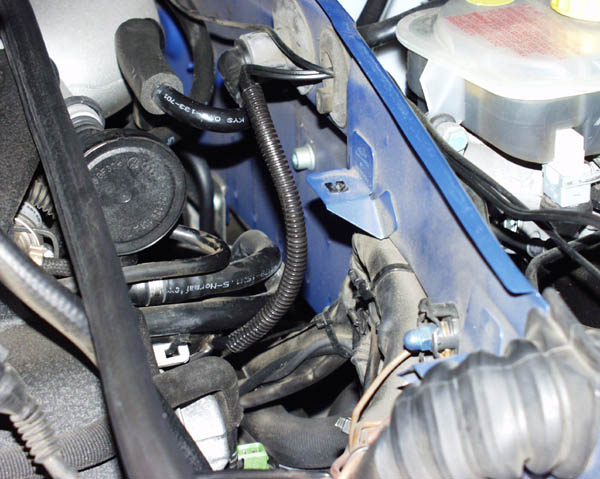
The circuit for this. It's relatively poor quality, even worse- drawn on an envelope! What can I say.. I had a burst of ideas while on the toilet and needed to get it onto paper before I forgot. That's all I had available to write on. Next, you need to track down the coolant afterrun circuit thermoswitch. This is a neat little green topped sensor mounted on the back of the coolant hardline attached to rear of the drivers side cylinder head. Ok ok.. I'll be nice and provide a picture. :) It's the green connector you're after.
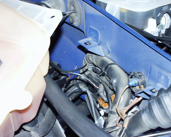
Your best bet is to remove the three phillips screws holding down the transparent coolant reservoir. Then just lift it out of the way. No worries about spilling coolant, it's sealed-- and that loose bottom hose attached to nothing is actually a vent so remember that it goes to the right of the metal heat shield and basically points down at the ground. With this out of the way, you have easy access at the sensor. To pull this sensor connector off you have to pull the metal retaining clip. This is done via flathead screwdriver. Make sure to not let it fly off into the engine bay. Then pull the connector off the sensor. This connector has a short length of wire attached to a larger harness. This short length is actually 2 wires. Brown with red and brown with blue stripes. The red wire is positive ~11 volts during engine operation and within 10 minutes of engine shutdown, but *don't* get the idea that you can just connect the brown/blue wire to any 12v+ source and expect the afterrun circuit to engage. You will fry your ECU if you do this. The way the system works is that the thermoswitch closes the circuit, connecting the brown/blue with the brown/red. If this happens within 10 minutes of engine shutdown, the afterrun circuit activates. We are going to simulate that with a relay. Now, there are two choices. You can peel the boot back about 3/4" from the end of the connector and cut it clean off (what I did) knowing that in the rare event you want to revert this back to stock, if your soldering skills are up to snuff you can easily splice it back in. --This does however disable the sensor (thermoswitch) but the ECU cannot detect this. Or you can splice two wires into the sensor wiring itself-- though that will definitely be more difficult. The circuit for this works fine either way, with the sensor intact or no longer being used. There are no conflicts if the sensor is legitimately activated with this circuit. Whichever you decide, use something small. Splice the wire to the two wires that go to the connector. 18 gauge braided pair black lamp cord works well, but is only rated to 100C. Something that can handle a bit more heat would be ideal, since it gets hot under the hood. Obviously, things like electrical tape are going to be completely out of the question. Do not use black vinyl electrical tape under the hood.. it will peel and fall off from the intense underhood temps. High temp heat shrink tubing is highly recommended. Next you want to route the wire through the firewall, into the ECU housing and then ultimately under the dashboard. We want to do this CLEANLY.. if you have wire nuts and zip ties laying everywhere under your hood, your dealer will take one look at it and simply refuse to work on your engine. Pics are provided, of course.
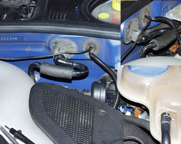
Route the thermoswitch wire through the unused firewall nipple. You will have to poke a small hole into it, then squeeze the wire through. Now the wire can enter enclosed firewall area cleanly. I passed both the boost gauge sensor wire for the MachV HUD /AND/ the afterrun sensor wire through this nipple. Shown here is the boost gauge sensor wire through the nipple, and the 18gauge paired stranded wire I used to hook up to the afterrun thermoswitch sensor not yet added laying on the side.
Remove your ECU cover per instructions HERE. Cut the end off the nipple entering the ECU enclosure. Then carefully push the thermoswitch wire through the outside end first. Lube the wire up with spit, seems to work well enough. Now would be a good time to route the MachV HUD boost gauge sensor wire through this very same opening if you're installing it at the same time. You can see my installation above, as you see two wires going through the nipple.
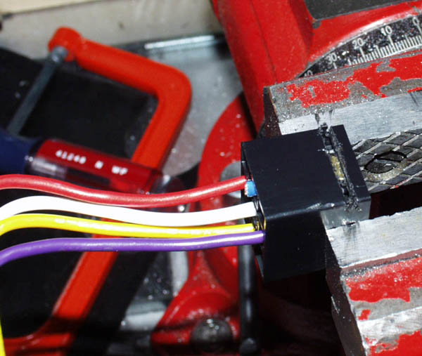
Shown here is the opening in the ECU enclosure. This opening leads down into the drivers foot well area. Yes, if you had a small enough hand you could reach up from behind the pedals and touch the ECU box. That enclosure is sealed from the outside (ie: water), and by using the nipple you will keep it that way. It will also keep your interior cabin quiet and noise free. My advice for routing the wires through that small opening is to place a flashlight into the ECU box aimed at the opening, then look behind the pedals in the cabin. You'll see the light and if your wires are laying there, will be able to reach up and carefully pull them through. Keep in mind that at this point you will want your front knee bolster to be removed so you can access the wires. Details on how to do that are at the above Greddy III installation hyperlink. Now you've got your afterrun thermoswitch wire in the bolster area. Time to wire it up to the relays. The circuit diagram details this well enough. Attach it to the turbo timer circuit. Using the radio shack harnesses: Purple is ground. Red is 12V+ to activate the relay. Yellow is power in, with White being connected to it unless power is provided-- then the circuit falls open. Blue is routed to Yellow when power is provided, but the circuit opens as soon as power is deactivated. Route the turbo timers Red wire to Constant 12V+, but do not route the Green wire to the ignition as you would if the turbo timer was stock. Instead route that to the relay wires indicated. Now we've got an isolated circuit that opens and closes with the ignition, that the turbo timer can work with which will ultimately control the afterrun circuit.
To keep this neat, I recommended those relay sockets for a reason. Cut slots in them like shown, and then you can slide/lock them into the spare stock relay mounts. There are literally 6 or 7 slots available. Poof. 3 relays that look stock and your wiring couldn't be cleaner. :) It will be easiest to get all your soldering and wire splicing done before mounting the sockets into the stock slots. It takes some finagling to get the sockets behind everything to slide into the slots from behind, but it can be done. Before proceeding, check ALL your connections carefully. Reconnect the battery. Turn on the ignition and let things sit for a few minutes while the computer recalibrates the electronic throttle. When everything gets a little quieter, turn off the ignition. The turbo timer should activate, but nothing should happen-- since the engine was never started the afterrun circuitry was never armed. Now, start the engine. Turn it off. The afterrun circuitry should be activated by the turbo timer. On mine I set my MachV to run the afterrun for 2 minutes, every time. The variable fuzzy logic circuitry is neat, and I may use it more in the future. Button everything back up, and enjoy! - Eric "Keman" Uratchko |
|
Advertising |
Contact Us |
Cookie Policy |
Privacy Statement |
Terms of Service |
Do Not Sell My Personal Information
© 2020 MH Sub I, LLC dba Internet Brands |


