| Tech Article Title
|
Author
|
Date
|
| S4
Valve Cover Gasket Replacement (Driver's Side) |
Andrew
(Qcrazy)
|
2004 |
Purpose:
Every Audi I have owned has leaked oil past the valve cover gaskets at some point. My 2000 S4 is no exception. An oil leak is unsightly and depending on the location of the leak can create a nasty burning oil smell. The oil leak on my S4 was in a location that sprayed oil down the bi-pipe when on the track. An interesting item to note with the S4 is that a valve cover leak actually creates a small boost leak. The boost leak is caused by air passing through the bleeder valve for the crankcase breather system and into the valve covers. While this is a small boost leak and is not noticeable, it's a boost leak nonetheless. For the reasons listed above, I set out to replace the leaking driver's side valve cover gasket on my S4. Below is the procedure that I used.
Tools Needed:
Phillips Screwdriver
Flathead Screwdriver
Pliers (optional)
Ratchet
Various Extensions
10mm Socket
13mm Ratcheting Wrench
Compressed air
A couple old shop rags
Parts Required:
1- Gasket set (2 piece)
2 - Small hose clamps or zip ties (vacuum line size)
1 - Medium hose clamp (BPV size)
2 - Large hose clamps (intake air duct size)
Brake Cleaner
Automotive Silicone
Spark Plugs (optional)
Procedure:
Step One:
Remove plastic engine covers. There are three separate covers over the top of the engine. If you do not know how to do this step...stop here!! :)
Step Two:
Remove the three screws that hold on the coolant reservoir. Once the screws are removed disconnect the level sensor from the bottom of the reservoir and move the reservoir to the side and out of the way. Do NOT disconnect the coolant lines!
Step Three:
Remove plastic cover over the driver's side valve cover. Remove oil cap and the two retaining clips. Pull off cover and then re-install the oil cap.
Step Four:
Remove intake air duct (y-pipe). To do this remove one large hose clamp on the passenger side rubber hose (the rubber hose that connects the intake lines and the BPV outlet). Remove one large hose clamp and the medium sized BPV outlet hose clamp on the driver's side, slide driver's side hose off BPV outlet. Remove the hose clamp on the accordion hose leading to intake air duct and remove from intake air duct. Next, remove the PCV connection to the y-pipe. Finally, remove three 10mm bolts that hold the intake air duct in place. Now the intake air duct is free; work the intake air duct free from the rubber hoses and set aside. Put a clean rag in the passenger side intake piping, driver side BPV outlet, and the accordion hose.
Step Five:
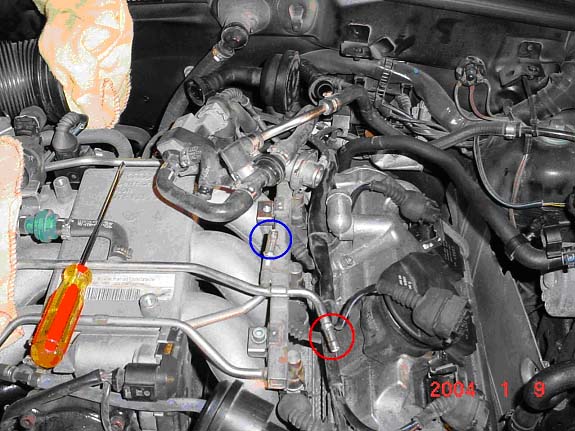
Remove the metal driver's side intake pipe leading down the side of the engine. This pipe is held in by one 10mm bolt that needs to be removed (#1 below). There's also a vacuum line running along the side of the intake pipe. The vacuum line is attached, via a zip tie, to the intake pipe at the location where the intake pipe is bolted down (#1 below). Cut the zip tie and slide the vacuum line out of it. Now remove the intake pipe by simply pulling straight up. After the pipe is removed put a clean rag in the remaining pipe below.
|

|
Step Six:
The next step is to loosen a coolant line on the driver side (#3 above). Near the intake pipe that was just removed is a coolant line that goes down the side of the engine. About half way down the engine a rubber line (coming the coolant reservoir) attaches to a metal line. Shortly after this change the metal line is attached to the side of the engine (#3 above). Remove the 13mm bolt using a ratcheting wrench. This bolt is removed to give the coolant line enough room to get the valve cover off
Step Seven:
Now is a good time to clean the grit out from around the edge of the valve cover. This is best done by spraying around the edge of the valve cover with some compressed air (can use brake cleaner if you have to). MAKE SURE ALL THE OPEN INTAKE LINES ARE STUFFED WITH A RAG. You can clean any oil residue off by using brake cleaner in those areas at this time as well.
Stop Eight:
Disconnect the coils. Slide the large metal retainer up using a small screwdriver and pull out the connector. Next disconnect the electrical connector at the front of the engine leading to the driver's side cam adjuster. Finally, cut the three zip ties that attach the harness to the valve cover and move the harness out of the way as best you can.
Step Nine:
Disconnect the vacuum line that was running along the side of the metal intake pipe. This line is held by one clamp near the fuel rail (#2 above, red circle below). Remove the clamp and pull the hose off then move the vacuum hose to the side. There's a hose support located near the back of the engine that holds a coolant line, driver side valve cover breather hose, and a vacuum line together. Remove/move this hose support.....don't forget to re-install. Next, remove the curved vacuum line by taking off one hose clamp (blue circle below). Now remove the rear 5mm allen bolt and move the whole vacuum hose assembly to the side (shown in moved location below).
|
|
Step Ten:
Disconnect the driver's side valve cover breather hose (shown disconnected above). Squeeze end together to remove, one may have to use a small screwdriver to help remove due to limited finger access. Do NOT force it!!
Step Eleven:
Remove the coils by taking out the 10mm bolts (2 per coil). Once the coil bolts are out pull the coil straight up to remove. Now would be a good time to change spark plugs on the driver's side if one needed to.
Step Twelve:
Finally, we have reached the valve cover!! Remove the valve cover by removing all the 10m bolts. There are eight 10mm bolts, six on the sides and two in the middle. Clearance is tight for the lower bolts along the driver side but they are accessible with a ratchet.
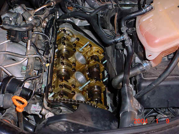
Once all bolts have been removed, pull off the valve cover. The valve cover may be stuck down until the seal is broken, therefore, one may need to "pop" the valve cover to get it free. If the valve cover seems stuck one can remove the oil cap and slide off the protective sleeve, then LIGHTLY tap the valve cover (towards the driver side of the car) with a dead blow hammer or rubber mallet (no metal hammers). Do NOT hit the valve cover hard. Once loose, pull the valve cover off.
|
|
In the picture above, you can see one piece of the old gasket around the outside of the head (outer gasket). Remove the gasket and clean the surface of the head with brake cleaner and a rag. Also, clean around the spark plug holes and bolts. Make sure all debris is cleaned from the surface of the head.
|

|
Above you can see the second portion of the gasket (center gasket). Remove this gasket and again clean up the outer and center surfaces with brake cleaner and a rag.
Step Thirteen:
Once all surfaces are clean get ready to install the new gasket set. The surface of the gasket has ridges on both sides. I decided to add a very small bead of silicone in the center of the gasket, between ridges. I used a Permatex High-Temp Gasket Maker Silicone. I went around both side of the center gasket and then installed the gasket on the head. The center section can install either way.
The outer gasket installs only in one direction. This section also has ridges on both sides and I again suggest applying a bead of silicone to the gasket. Prior to applying silicone to the outer gasket one needs to add silicone in a few locations on the head. One needs to add silicone at the ends of the cylinder head as shown below (arrows). On the front driver's side there is also a small "valley" along the cam tensioner. One should apply silicone in this "valley" as well. Apply silicone to cylinder head using a small screwdriver, you will not need much silicone for this. The lower front end and "valley" areas are hard to reach, you will need a steady hand.
Now you are ready to install the outer gasket. First apply the silicone around the ridges and then install the gasket. I also applied a small amount of silicone along the bottom edge of the gasket that was inserted into the "valley". Once you start applying the silicone you will want to move fast, you should have the gaskets installed within 10-15 minutes after you first start applying silicone.
|

|
|

|
Above you can see the red silicone I used at the ends of the cylinder head. Where this silicone is applied is where my initial leak was. After removing the gasket I noticed that I had been leaking oil around the "valley" as well. In the picture above you can also see the small bead of silicone around the center gasket.
Step Fourteen:
Once the gaskets are in place reinstall the valve cover. When installing the valve cover bolts, hand tighten all bolts initially. Then proceed to tighten the rest of the way by turning each bolt 1/2 turn and going to the next bolt. This will ensure that the gasket is compressed evenly. Valve cover bolts should be tightened to approximately 7 ft-lbs.
Due to the amount of silicone used I would suggest waiting overnight for the silicone to set-up. Exact time required depends on amount and type of silicone used.
Installation is reverse of removal. Once done, start the car and check for leaks.
Total Time: 3-5 hours
Disclaimer:
This is the procedure that I used to replace the driver's side valve cover gasket on my 2000 S4. This procedure will be applicable to all B5 and C5's with the 2.7T engine. The previous write-up was just a description of the procedure I used to replace my driver's side valve cover gasket. Attempt at your own risk.