The procedure described below carries the usual rubric about not being responsible for any unfortunate consequences arising from failure to observe appropriate safety protocols and practices or injuries deriving from attempts to follow the plan laid out below.
*NOTE!*
After going through a fair amount of preparation especially studying closely baysideS4’s excellent piece on much the same operation on an S4. I thought someone out there might appreciate an account of replacing the auxiliary water pump on a 2001 A6 2.7T 6-speed, with notes of a few differences and one or two alternative approaches. If nothing else, you can save yourself a few hundred bucks and feel some pride and accomplishment to boot. Beyond that, given the debris and detritus I encountered beneath the manifold, I can’t imagine any regular Audi or other mechanic spending the time I did removing this stuff, so I felt additionally chuffed for doing the extra laps.
OK, so this is essentially a follow-up to the posting by BaysideS4’s very helpful write-up on replacing an auxiliary water pump on an S4. Thanks to his description and photos I felt sufficiently confident to tackle my A6 the first job I’d done on this car. I’ve noticed a number of remarks or questions from time to time in Audi Forums relating to similarities/differences between the S4 2.7T and A6 2.7T engines.
Several differences are clear in points relating to the intake manifold. Probably the most significant is the number of bolts holding the manifold down: the A6 has 18 rather than the ‘13 or so’ cited for the 2001 S4. A mere comparison of the photos of the A6 manifold with those provided by BaysideS4 will establish differences in design. Perhaps these differences merely point to a delay in implementing altered components in one or the other engine.
A few other discrepancies are worth knowing about, some concerning the layout of the vacuum lines etc., but I’ll note these below as they come up. The pump and gaskets, however, are identical: part nos. 078-965-561 (pump) and 078-129-717-N (gaskets). Like BaysideS4, I picked up a new pump, manifold gaskets, and a batch of small screw-type stainless clamps for the vacuum lines, some larger ones for the coolant hose connections at the pump, and a couple of 2 1/2 inch diameters for the front Y-pipe connections.
Before embarking on this job I consulted Bentley, which provides some potentially useful diagrams and drawings and so on, but sets out a considerably more elaborate, time-consuming, labour-intensive procedure (involving special tools, at some points), a good proportion of which is unnecessary (e.g.removal of the bumper, the service position for the lock carrier, disconnection of fuel lines, and removal of the viscous fan as well as the turbo tubes at the front).
A very important benefit of BaysideS4’s approach is leaving the fuel lines undisturbed this substantially simplifies and reduces the messiness, etc. of the operation and obviates the need to depressurize the fuel system, etc. No doubt someone will find this blameworthy, but I didn’t disconnect the battery either I just couldn’t see what electrical components might be affected by the operations. There are various electrical connections to take apart, but, as far as I’m aware, nothing that carries current with the ignition off, and I covered at least one of the male or female electrical connectors with a small plastic bag to reduce significantly, if not eliminate, any chance of an inadvertent short. In any case, I ran into no problems as a result maybe I was just lucky and I had no recoding to do afterwards.
Before starting, I tried to find a magnetic 5mm allen head that BaysideS4 cites, but without success. In the end I improvised with a couple of small rare-earth (neodymium) magnets (about 3/8 inch diameter see photo below) on the shaft of the drivers I used and can recommend these for anyone who has trouble locating the magnetized wrenches. These magnets are amazingly powerful and hold the bolts securely. They may also come in handy for retrieval purposes, if by any chance a bolt or other steel object falls into the V or elsewhere. I chose to use plastic bags held in place by rubber bands to protect the ends of various larger hoses and tubes, if only to avoid any lint problems from rags stuffed inside; but I used rags for a few smaller pipes see pictures.
I should note at the outset that what led me to the auxiliary water pump was a modest but consistent loss of coolant over a period of a month or two prior to fingering the auxiliary water pump as the source. From time to time I found that the level in the reservoir had gone down an inch or more, and I remember noticing a distinct antifreeze odor on the highway on one occasion. When I had a moment for some forensic investigation, I put the car on ramps after a good drive and got underneath where I could see pink fluid trickling from somewhere around the rear of the engine’s V. By crawling over the engine and shining a flashlight from above, I discovered the culprit: coolant appeared to be seeping literally from inside the electric motor that is part of the pump i.e. it seemed to be emanating from between the casing and the plastic at the end of the motor, giving the impression that the liquid was escaping internally somehow more on this later.
A related matter concerns a check engine light and code relating to overheating (turned out to be a faulty coolant temp. sensor I’ll submit my write-up on this in due course). I was in no particular hurry when I began, so I didn’t try to keep to a tight timeline. I split the operation over a couple of days, working on it on and off maybe eight or ten hours in total. But a substantial proportion of this time was spent cleaning around the intakes to remove stacks of maple keys lodged in the cavities and channels below the intake manifold in the V, some rotting in a pool of coolant and others just playing hard to get under tubes and in virtually inaccessible sluices and canals. That aux pump seems to have been determined to build a comfy nest down there.
The first stage of the process naturally involved removing the plastic covers on top and the Y-shaped pipe from the air filter. As with the S4, the crimped factory-installed clamps here and on a number of vacuum lines had to be removed a screwdriver and small vise-grips proved most useful for this. I chose to use regular screw-type stainless clamps as replacements. I’d like to have found some narrower than the half-inch wide pieces I ended up using for the legs of the Y-pipe, but I couldn’t locate any. I also removed the plastic cover from the oil-filler bank (driver’s side) of cylinders. I didn’t bother taking the other bank’s cover off, nor did I remove the accordion hose from the air filter to the Y-pipe or the air filter housing (none of these seemed to be necessary), and there was ample room to maneuver without doing so.
The wide accordion hose at the rear has a vacuum line attached to its underside that leads through the firewall to the brake booster. I left this in place I’m not sure what needs to be done to detach it, but in this case, it didn’t really matter since access was not impeded by leaving it in place. There is, however, another larger black plastic or nylon vacuum connection at the back (firewall end) of the manifold fitted with a black nylon collar that releases when pressure is applied simultaneously to the opposed free sides of the collar. This called for some fiddling to disconnect; I just couldn’t seem to be able to apply the requisite amount of force with my fingers, so in the end I used some small vise-grips or pliers that allowed for the application of pressure without crushing the tube or breaking the nylon. This line needs to be disconnected to enable the manifold to be lifted high enough for access to the pump.
When it came to disconnecting the wires leading to the throttle body boot (TBB) held in place by the nylon zip-tie, I decided not to cut the tie, but undo it instead. By lifting the foot within the gate that holds the corrugated tail in place, the latter can be withdrawn and the zip-tie can then be re-used. For this purpose I used a very small jeweler’s common or vulgar screwdriver. The two larger plastic turbo pipes at the front that come up at angles on each side that lead to the TBB have enough play to allow the forked rubber housing to be disconnected fairly easily but with care and patience. As other commentators in AW Forums have remarked, the TBB is one of the weak links in the turbo system (the others being the bypass valves or BPVs and the plastic vacuum lines to the BPVs see below). In this overview you can see the Y-pipe has been removed and the coolant expansion tank (already drained) banked over on the driver’s side (tighten the cap securely after draining to minimize coolant loss when it comes time to disconnect the pump).

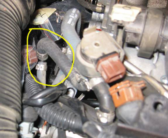
Here is my socket wrench loaded with a rare-earth magnet (I also fortified a T-handled allen wrench with one of these) and, circled in red, a similar, but apparently not the same, set of vacuum connections as found on the S4 that attach to the recirculating valve for the turbo (N249). Since on the A6 they did not prevent access to the manifold bolt below, disconnection was not required. I only removed the driver’s side bank plastic cover as in BaysideS4’s case, I was planning to lift the manifold from this side (the fuel lines come over from the passenger’s side) and cover removal improved access to various components, so this seemed advisable. But apart from a wish to clean up the passenger’s side cover (which I did on the outside at least), there was really nothing to recommend taking it off; it would have meant taking out or disconnecting various components unrelated to the task at hand, so simple efficiency trumped thorough cleaning in this case.
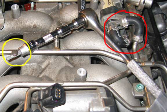
The yellow ellipse singles out the vacuum line that runs from the bottom of the accordion intake pipe to the firewall as noted, I left this attached (in order to get at the coolant temp sensor in a later operation, I needed to disconnect both spring clamps and move the accordion pipe out of the way another story).
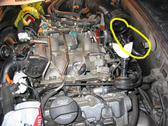
This overview shows one of the BPVs circled in red disconnected from its bigger tubes the slender vacuum lines can be left in place so that the BPVs remain loosely attached, unless of course you were minded to replace them with a pair of 06A145710N’s, as per AW Forum recommendations (except for those who favour Volvo BPVs), and while you’re at it, the narrow vacuum lines, and possibly even the TBB this would certainly be an excellent opportunity. In yellow is the N80 cluster this is the EVAP valve encircled by a rubber collar that slides off (toward the rear) a steel tongue below. The electrical connection to this needs to be parted also; but the rubber tubes attached to the N80 should be left in peace (see other shots below).
In this snap I’ve circled a bolt near the dipstick (there’s one on either side) that holds a bent metal connector near the front that holds the adjacent electrical link (for knock sensors). My magnet-loaded T-handled allen was very handy for dealing with these.
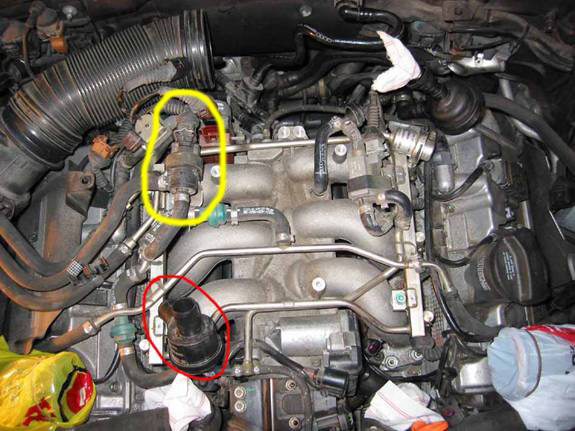
Circled in yellow is another set of three vacuum connections, near the firewall on the driver’s side, separated from their plastic nipples. These proved particularly difficult to get apart, but finally yielded hard sometimes to know how much force to apply to these plastic parts, but care and patience were rewarded in all such cases. After working on several of these and there are quite a few in total I found that a twist of the rubber tube to free it from the heat and habit bond at the nipple significantly assisted disconnection. As BaysideS4 explains, a flat screwdriver can also be helpful in dislodging stubborn vacuum connections.

This is a view of several vacuum connections at the rear of the passenger’s side bank. I strongly recommend labelling all of these and other connections as you disconnect them to simplify reassembly. In this case I uncoupled only the black one seen circled on the left and the light grey one just above the clamp visible at the right side of the circle. The left connection is a three-way inverted Y, but only the top tube needs to be separated. The second, light grey one is a simple plastic splice I disconnected the upper hose from the nipple.
Here are the respective tubes disconnected (also shown to the right is a separated electrical link at the wastegate bypass regulator valve, or N75):

Before loosening the manifold bolts, I tried to clear debris (mainly the maple keys and an accumulation of sand and grit) from around the manifold. I used compressed air to dislodge a fair amount of this, but had to resort to needle-nose pliers, tweezers, tongs, and other devices to get at the keys. The previous owner must have regularly left the hood open under a maple tree in late spring or summer to the delight of that little pump I can’t otherwise imagine how the keys could have got so deeply buried inside.
Next I disconnected the electrical couplers on the injectors. After this, the wires to the injector couplers need to be followed closely and moved out of the manifold’s way (if I remember correctly, there are one or two zip-ties on the driver’s side that require undoing here same method as described above). I think that pretty well covers the series of hoses, electrical junctions and so on that need to be disassembled; but you may wish to review the situation just to make sure (I did this early last November, but have not had a chance to write it up until recently). Once that’s done it should be possible to unscrew the 18 bolts and lift the manifold:
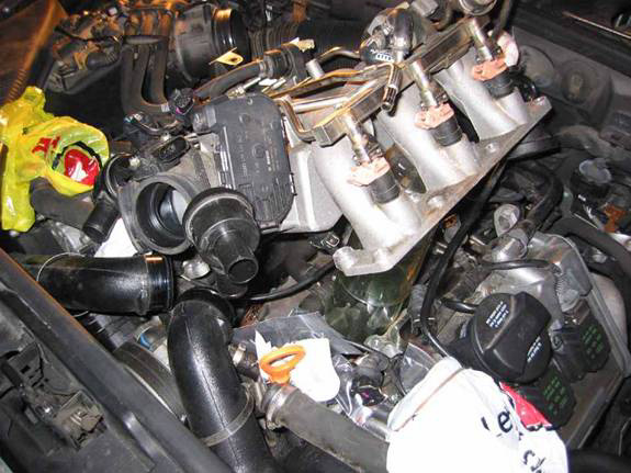
As you can see from the above picture, I left the ‘N249 cluster’, or turbo recirculating valve (driver’s side rear), in situ on top of the manifold rather than removing it and using the reservoir to hold it out of the way (as BaysideS4 recommends) I don’t know if the connections on the A6 are just slacker than on the S4, but there was no need to take the cluster off. After raising the manifold, I propped it up and then covered the intakes with masking tape so that I could proceed with the cleaning operation without fear of dislodged debris entering the chambers. I used a small dull chisel (with a 4 mm blade, 12 cm long including handle) very carefully to scrape loose the accumulated sand and grit and then vacuumed it up, applied compressed air, and finally carefully wiped the surfaces down.
As BaysideS4 noted, once the manifold is out of the way, exchanging the pumps is a piece of cake. If the expansion tank is drained of coolant beforehand (I found a dollar-store siphon worked best it can be positioned at different points and at different angles in the reservoir’s internal labyrinth to get most of the coolant), and the cap is securely replaced, there shouldn’t be more than a negligible loss when the rubber hoses are disconnected from the pump. On the A6, the pump fits into the rubber base of the bracket fitted with four projecting capped studs that seat in keyhole-shaped openings; when moved towards the firewall, I think (it may be the other way, but trial and error should be pretty simple for this operation), the studs reach the wider diameter ends of the keyholes and the pump lifts out freely. To my surprise, on the A6 the rubber coolant pipes are held in place by spring-type clamps. The outlet pipe, as you can see from the accompanying photo, was coated along the side and bottom with accumulated residue from dried-up coolant which may have originated from a bad clamp, the internal pump leak, or both. I decided to use two screw-type clamps at each connection as a precaution against having to go through this whole procedure again in the event of a faulty clamp. My cottage plumbing experience has taught me that doubling clamps adds significant (and cheap) insurance to this kind of connection.
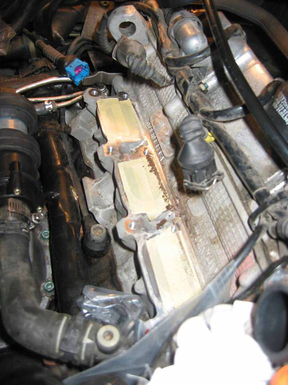
The following shot gives a glimpse of the encrustation at the aux pump inlet tube (also the OEM spring clamps), suggesting clamp leakage, as well as some of those pesky maple keys (circled in yellow):

At one point in the process I contemplated repositioning the aux pump where it would be more accessible, but after reviewing several locations, decided against it since practically every vacant space might in future impede access to other components. Yet more keys!

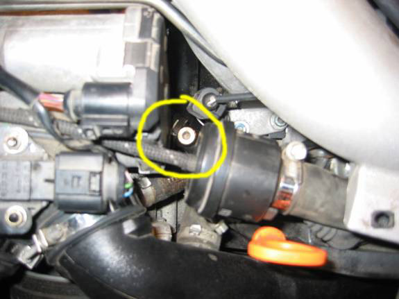
Here you can see a bolt below the pump (circled in red) electrical connection with a socket full of pink coolant, and, depending on how the colour registers, more below that:

This shot shows the taped intakes on the driver’s side bank and some of the crud that was waiting to fall into them if left unprotected. Dangling above are two injector connectors.
Care in placement of the new manifold gaskets and careful positioning of the manifold, making sure no unwanted wires, etc, get in its way should get reassembly off to a good start. *Update 11-13-2006* Several AWers who have replaced the pump themselves since this piece was originally posted have had the misfortune of inadvertently crimping a wire between the manifold and one of the cylinder heads in the torque-down operation (e.g. absolutcq20v on 2006-02-11 05:53:42, jases2.7t on 2006-02-10 20:42:19, expatkiwi on 2006-09-26 20:09:28): one post specifies the harness under the driver�s side upper corner, possibly incorporating the cam sensor cable cited by another. You�re likely to run into potentially serious consequential problems if this occurs, so in your eagerness to put it all back together, take a moment to pause and exercise extra caution by ensuring that all wires are accounted for and clear before tightening the manifold bolts.
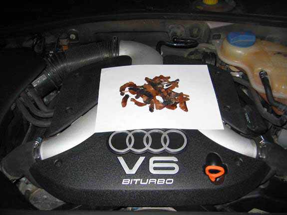
Bentley interestingly specifies that the manifold bolts should be torqued to 10 Nms, which as it happens is the same specified for the screws holding the coolant expansion reservoir in place! Clearly, a measure of restraint is called for when it comes to battening the manifold down. The rest is simply a reversal of the disassembly operation, and the addition of coolant to the reservoir at the end. A modest memorial to the clean-up operation:
I took the leaky pump apart after installing the new one and found that coolant seemed to have been seeping down the armature shaft into the motor itself; I couldn’t find any other explanation for the liquid escaping from the motor, though reconciling this with the essentially independently encased pump unit is problematic. I have seriously wondered from time to time whether the inadequate spring clamps were really to blame. The pump consists of two magnets: one connected directly to the electric motor shaft which in turn drives the other magnet to which is attached the pump in its enclosed and supposedly sealed chamber. The surrounding 0-ring and the plastic encasement appeared to be intact but may have had a pinhole leak. Interestingly, a few small plastic pieces had broken off the pump end, but nothing that would affect it's operation or contribute to the leak. Another operation that could have been pursued at this stage is draining and refilling the cooling system, taking all the precautions for eliminating air. Of course, under working pressures the effect of a minor hole or crack would be significantly magnified. Whatever the circumstances, some coolant seems to have crept down the motor’s shaft and come out the other end, though this could have been an optical illusion I didn’t take the motor itself apart. When I attached the pump to a 12 v supply and linked it to a water faucet, it seemed to work fine, though hardly the equivalent to service conditions.
Anyway, there it is. I did this operation without assistance some additional hands might have been helpful from time to time, but were not really necessary. In the event that you find yourself facing this challenge, you can of course comfort and console yourself with the thought of how much money you’re saving, but you might also derive some satisfaction from doing a much better and more thorough job than a mechanic’s timesheet would allow. My A6 had done about 87,000 km when this problem arose. I don’t know how many 2.7T owners have had a similar experience, but my brother alas, recently deceased, who had a lightning-fast chipped and modified 5000 Turbo Quattro, scoffed at my dismay over the need to dislodge the manifold to get at the pump and pointed to an auxiliary pump right out in the open on his engine! Oh well, I have a gratifying sense of satisfaction for my labours, and I also gained some valuable in some respects, intimate knowledge of parts of the engine. Faced with the project again, I figure I could do it in maybe three hours or less (of course I wouldn’t have the maple keys to contend with).