| Tech Article Title
|
Author
|
Date
|
| UUC Short Shifter Install -- S4 Biturbo |
Tom Barber |
2001
|
7/3/00 NOTES: The following article on the installation of the UUC Short Shifter was written in mid-March, 2000. I have just made a few updates, but this is in all likelihood the last time that I will do anything with this, so please be aware that depending on just when you are reading this, UUC might have made changes to the product that render some parts of these instructions obsolete. As of this date, they have added the option for 40% reduction, which is not discussed in these notes.
(The style of these instructions emulates a book that is titled something like "How to Keep your Volkswagon Alive... step-by-step instructions for the compleat idiot". This was the first car maintenance manual that I ever read, back in the early '70s when I worked on the first car that I owned, a '71 Super Beetle. The most recent update of that book is still in print, and whether or not you own a Volkswagon Beetle, it is a very readable book that contains a lot of basic information on automotive mechanics.)
BEFORE BEGINNING, HERE ARE A FEW NOTES ABOUT THE DIFFICULTY OF THE INSTALLATION, CIRCLIP TOOLS, THE SHIFTER LEANING TO THE RIGHT, AND ALTERNATE APPROACHES TO THE INSTALLATION.
BEFORE YOU COMMIT YOURSELF EMOTIONALLY TO DOING THIS INSTALLATION YOURSELF, note that while it is not technically complex, it does require patience, dexterity, and some mechanical skill. If you aren't accustomed to dealing with challenging mechanical problems or if you have large hands, you should consider having someone else do this. The average novice installation time appears to be about 2 hours. Please follow these instructions one numbered step at a time, being certain to read and understand the entire step completely before starting to perform that step.
A FEW WORDS ABOUT CIRCLIPS AND CIRCLIP TOOLS: Please be advised to not attempt to do this with needle-nose pliers. There are two kinds of circlips, and the shifter mechanism has one of each type. One is a small "outer", i.e., it surrounds the shaft and is spread open. The second one is a large "inner", i.e., it slips into a cylinder and is held in compression. When you go to the hardware store and look for "circlip/snapring pliers", you will find that there are pliers for inner circlips and there are pliers for outer circlips. The difference in the tool is whether the action of squeezing the grip translates into compression, like normal pliers, or expansion. The tips on the tool for the large inner circlip must open at least a full inch when the grips are fully separated. The tips can be straight, 45 degrees, or 90 degrees. I found a single convertible pliers with interchangeable tips at Sears for about $12. It had a moveable arm that allowed it to be converted between inner and outer, and it was perfectly adequate for this job. I found the straight tips easiest to use.
A FEW WORDS ABOUT THE UUC SHIFTER LEANING TO THE RIGHT: With the stock shifter, when the transmission is in neutral, the shaft will be very nearly vertical, with little if any perceptible lean to the right or the left. Because the neutral position is between 3rd and 4th, when in either of those gears the shaft will have little perceptible lean to the right or the left, but will lean to the left when in 1st or 2nd, and will lean to the right only when in 5th or 6th. With the UUC shifter, however, at least with the one that they shipped to me and most other people prior to the time of this writing, the shaft leans to the right when it is in 3rd/neutal/4th, and exhibits almost no lateral lean when it is in 1st/2nd.
These instructions will tell you how to correct for this, and will explain why this is so, but it is important to first note that yours might not manifest this attribute, and even if it does it might not bother you. Therefore, please do not make the correction that is described here until you have verified that yours is this way and have determined that you want to correct for it. The reason that it leans to the right (if in fact it does) has to do with the little knob-like protrusion on the right side of the shaft. That knob is there so that you will have to push the shaft down in order to get it over far enough to go into reverse. What happens is that as the shaft is leaned to the left, as though to put it in reverse, this little knob-like thing, which is located on the shaft just below the pivot ball, swings to the right and bumps against a surface on the plastic tray that holds the pivot ball. (You will be able to see this easily once you have the pivot ball out.) The distance that this little knob-like protrusion extends from the center line of the shaft determines (absolutely) the amount of lateral lean that the shifter will have when it is properly adjusted so that 1st, 2nd, and reverse engage cleanly with no excessive resistance. On the stock unit, this distance, roughly measured, appears to be about 7/16 inch, whereas on the UUC unit that was shipped to me, this distance is about 1/16 inch greater, and that is the truth, the whole truth, and nothing but the truth as regards whether and why the UUC shifter leans to the right more than the stock unit.
A FEW WORDS ABOUT ALTERNATE APPROACHES TO THE INSTALLATION: A few other people have indicated that they were able to simplify the installation by removing the brass rods (the ones that the black plastic pivot ball tray slides on), or that they were able to rotate the unit and remove it without loosening the hinge bolt, i.e., with the two main components assembled at the hinge bolt. I had tried both of these methods before anyone posted anything about them, because they are obvious things to attempt. I was not successful with either one. As for removing the assembly at the Torx bolts that hold down the brass rods, I couldn't even access the Torx screws due to the thick pressed metal part that is the infrastructure of the center console tunnel. As for removing the unit with the hinge bolt intact, I had tried diligently to do this after I had the UUC unit installed, when I was making the adjustment so that it would not lean to the right. I rotated the unit completely around 360 degrees, i.e., turned it upside-down, but was not able to pull it out through the hinge ball opening. However, it might be possible to remove the stock unit that way. Also, if you make a mistake and install the lower section upside-down, you should be able to correct that by rotating the unit, but only if you also installed the upper section backwards. Notwithstanding that I was personally not successful with either of these two techniques, it goes without saying that if you find that either of these techniques works for you, particularly if you can get clear access to the torx bolts that hold down the brass rods, these techniques should make the installation easier.
ONE FINAL BIT OF ADVICE BEFORE BEGINNING: It is best to do this in the full light of day with the sunshade pulled back, but if you must do this in a garage where the light is less than ideal, you can set a flashlight, pointing downward, on the cup holder that pulls out the from the dash.
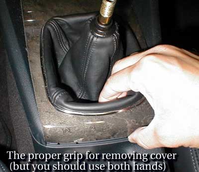
STEP #1: REMOVE SOME STUFF. Twist off the shift knob. If you didn't already guess that this was counter-clockwise, stop now and go find someone to do this for you. I'm not sure what car is shown in the picture in the UUC instructions, but the S4 is different in that the leather boot is set in a removable cover plate and is held in with clips underneath. Don't try to remove the boot the way that is shown in the UUC picture.
 Instead, remove the plate by reaching into the rear of the leather boot with the tips of your fingers just far enough to feel the lower edge, and with your thumb at the rear edge where it curves down, pull it gently but firmly straight up until it releases. Rotate it up to about 30 degrees, then begin gradually pulling it out from under the ashtray as you rotate it from about 30 degrees to about 45 degrees. (The plate has a curved lip at the end under the ashtray.) There are two little metal parts that locate two pins under the plate, and these may lift and fall, so be sure to recover them and set them with the plate so that you will remember to put them back on. Next, remove the black plastic collar, and then using a 10mm socket, remove the two nuts that hold the foam plate, and lift the foam plate off. Instead, remove the plate by reaching into the rear of the leather boot with the tips of your fingers just far enough to feel the lower edge, and with your thumb at the rear edge where it curves down, pull it gently but firmly straight up until it releases. Rotate it up to about 30 degrees, then begin gradually pulling it out from under the ashtray as you rotate it from about 30 degrees to about 45 degrees. (The plate has a curved lip at the end under the ashtray.) There are two little metal parts that locate two pins under the plate, and these may lift and fall, so be sure to recover them and set them with the plate so that you will remember to put them back on. Next, remove the black plastic collar, and then using a 10mm socket, remove the two nuts that hold the foam plate, and lift the foam plate off.
STEP #2: OBSERVE. Before you remove the two circlips, take a few minutes to study a few things. Make sure it is in neutral, then look at the two bolts that are forward of the shaft. These are the two bolts that have the 6mm Allen heads. The upper one joins the black plastic tray that holds the pivot ball to the upper linkage rod, and allows the fore/aft position of the pivot ball (and the fore/aft lean of the shifter) to be adjusted. The other bolt is below and to the left. It joins the lower linkage rod to the lower, horizontal arm that is attached to the bottom of the shaft via a hinged joint. Note that immediately under the head of the lower bolt, there is a small curved clamp. Immediately under the clamp is the flattened rear end of the linkage rod, which is similarly curved and also has a wide groove. The bolt goes through the groove in the linkage rod and screws into a threaded hole in the forward end of the horizontal arm of the shifter mechanism.
The reason that these parts are curved, that the groove is so wide, and that a clamp is needed, is that this allows the relative rotation, or twist, between the linkage rod and the lower arm of the shifter to be fine-tuned. The twisting action applied to the linkage, together with the fore/aft movement, is what determines which gear is engaged. When the shaft is tilted to the right or the left, this causes a twisting action. In order for it to work correctly, when the shaft is in any given position corresponding to a specific gear, the amount of twisting action that is applied in that position must be just so. If it weren't for the little knob-like protrusion that I discussed previously, you could be sloppy with it and get it to work easily as long as you aren't to picky about whether it tilts more to the right or the left than you think it should. However, the little knob-like protrusion absolutely determines the amount that the shaft must tilt laterally for 1st, 2nd, and reverse, and if the amount of twist action applied to the linkage rod when the shaft is in one of those fixed positions is not correct, it will not go into one of those gears. Thus, on re-installation, the tightening of the lower bolt that attaches the lower arm of the shift mechanism to the linkage rod must be done with care or else it will not work.
STEP #3: REMOVE THE TWO CIRCLIPS, THE PIVOT BALL, AND THE TWO ALLEN BOLTS. When you remove the small circlip (or when you put it back on later) be careful not to spread it too far, or else you will stretch it. This is NOT hard to do, and UUC ought to include a spare one of these (maybe they did in your kit). Remove the small white plastic part and the thin spring. Notice that the larger plastic piece that sits over the pivot ball has a protrusion near the top on the passenger side, and an opening directly opposite on the driver side. This is a housing for a spring that sits behind a plastic bullet and presses the bullet against the shaft. When you pull this piece off the shaft, the spring will force the bullet across the space and into the opposite side, and it may shoot through and out on the driver side. Hold your hand over the opening on the driver side as you pull it off. (It won't hurt.) The pivot ball, the two black rings, and a metal plate will slide up and off along with that top piece and will stay together as a unit. Now go ahead and remove the two 6mm Allen bolts. When you remove the lower one, BE CAREFUL NOT TO FLING THE LITTLE CLAMP OR THE BOLT FORWARD INTO THE LINKAGE TUNNEL.
STEP #4: REMOVE THE STOCK SHAFT AND LOWER ARM. Notice that the UUC shifter consists of two heavy pieces that are hinged together by a special bolt. That bolt is actually smooth along all of its length except for where the nut attaches, and there is a smooth nylon (teflon?) bushing around it. The stock unit that you will remove has a similar arrangement and a similar bolt, and you have to remove it in order to remove the stock unit. Tilt the shaft forward and pull the whole thing back as far as possible so as to expose as much of the lower arm as is possible at the rear of the black plastic tray. Forget about trying to get to it by pushing the bottom toward the front. Some people have claimed that it is possible to wriggle the thing out through the opening where the pivot ball goes, but I tried that and was not able.
On the stock unit, on the driver side, the head is recessed, so you will likely not be able to get an open-end or box-end on it. You may have to use a socket, but you might not have room for a regular ratchet, depending on how thick it is. I used a special 10mm box end that was 12-pointed, and that was offset so that the handle was not in the way. On the passenger side, you will be able to use an open-end or a box-end, possibly even a ratchet box-end. (If you happen to have the "squeeze wrench" that is sold via direct-marketing on TV, then you are in luck.) The distance that you will be able to turn the wrench before having to re-position it will be minimal, so a 12-point wrench will be a huge advantage. Even if you are able to get a ratchet on it, it might not help, for a couple of reasons. Ratchets vary as to the number of catch teeth per turn, and also if there isn't enough friction in the nut threads to overcome the small force needed to push the pawl over the ratchet teeth, the socket will merely rotate back along with the handle. The main thing here is to be patient. As soon as you have turned it a half turn, be content that you know that you will eventually get it off and that it is just going to take a little while. When it is nearly off, the nut and the bolt head separate wider, and this changes the problem somewhat, depending on what kind of wrenches you are using.
STEP #5: INSTALL THE UUC SHAFT AND LOWER ARM. When you put the lower, forked part of the UUC unit in, make sure that you don't have it upside down. The hinge hole belongs toward the top. The little knob-like protrusion goes on the passenger side. Before you put it in, study the location of the hinge hole relative to the large section at the lower end of the shaft, so that you will be able to visually get the two parts to line up almost perfectly without having to fidget with it. Then insert a small right-angle Allen wrench into the hole and wiggle it around to line up the two parts correctly. If you get them to line up correctly, you should be able to simply slip the bolt straight in from the passenger side with no difficulty. Then using just your left hand, and twisting your upper torso so that the open side of your hand faces the front (assuming that you are in the driver's seat), twist the nut on using your thumb and forefinger while using your smaller fingers to keep the bolt from coming out or turning. If this doesn't work for you, try placing duct tape over the head of the bolt so that it won't turn as you turn the nut. You should find that one of these methods will work until the bolt hits the plastic lock ring in the nut.
The bolt that UUC supplies has a knurled head, and the locking nut has a 3/8 inch head, but if you don't have English tools, a 10 mm metric tool will work just fine. (3/8" = 9.5 mm, so for low-torque applications a 10 mm wrench will work on a 3/8" bolt head, but not vice versa.) Again, a shallow 12-point box end is recommended for the nut side, unless you are able to get a ratchet socket to cooperate. The knurled head accepts a small Allen wrench, and if you have one the right size, use it. According to the directions, this is a 5/32" Allen head, but according to e-mail that Ben Liaw mailed, it is actually 1/8". (Someone told me that theirs came with the Allen wrench.) I didn't think that I had the right size, so instead I held a pair of small needle nose pliers tightly on the knurled part. This worked, but it would have been easier to have held the nut in place while turning the bolt head with the proper Allen wrench. It is very important not to over-tighten this, because if you bind the thing and then have to loosen it, the lock nut might not hold. The proper tightening is just to where there is enough friction so that you can't turn the bolt in the bushing using your fingers. If you do over-tighten it so far as to bind the shaft and the lower arm, it should be possible to loosen it a little and then put some sort of glue such as Loctite on the end of the lock nut, but if you do this be very careful not to compound the error further by letting the glue seep in between the bolt and the bushing.
STEP #6. RE-INSTALL THE PIVOT BALL AND THE CIRCLIPS. Before putting the pivot ball back on, start the two 6mm Allen bolts. Tighten the upper one just to where it will hold the black plastic tray securely, locating the tray fore/aft so that bolt is roughly centered in the slot. Set the end of the linkage rod on top of the other piece and look to make sure that the slot in the end of the rod is lined up over the threaded hole. Set the clamp in place and start the lower bolt a few turns, but leave it very loose. Before assembling anything, put some high-quality grease, such as white lithium, generously on the shaft where it slides into the pivot ball, on the pivot ball, and on the surface of the tray where the little knob slides against it (if you can't figure out where that is, put some on the knob itself and then after you have it installed you will know.) Also, before you re-install the foam cover plate, put some grease on the brass rods.
Put the pivot ball stuff back on and replace the large circlip. Replace the thin spring and the small white plastic part with the spring-loaded plastic bullet. Remember not to stretch the small circlip. There is a groove in the shaft for it. You will have to pull the shaft up with one hand while pushing the circlip down, compressing the thin spring. If you can't get the circlip into the groove, push it down as far as you can, and then use a small flat blade screwdriver to slide it down the rest of the way while pulling the shaft up with your other hand. Go ahead and screw on the shift knob.
Now comes the critical step that will determine whether or not it will work properly on the first try. You have to hold the shaft at the proper lateral tilt (and also fore/aft tilt) while tightening the lower bolt. The correct tilt depends on how far the knob-like protrusion extends from the center line of the shaft, and because there appears to be some variation in this, I cannot tell you what is the correct amount of tilt. What I can do is give you an idea of where to start that should work for the majority of the units, which is roughly 10 degrees toward the passenger side. The correct fore/aft tilt is a very slight tilt to the aft. (Notice that the black plastic tray is tilted up slightly in front. Hold the shaft so that it is perpendicular to the tray, and then push it forward about half the distance to vertical.) The best way to get the lateral lean correct is by looking at the bolt. Note that because the bolt goes in the threaded hole in the lower arm, that the lean angles of the shaft and the bolt are fixed with respect to each other. The lower arm and lower linkage rod should be positioned far enough to the left of center to permit you to get the hex bit with an extension on it, and the bolt should be almost perfectly vertical, but with a barely perceptible lean to the left. Make sure that the linkage is in neutral. If you are not sure, tighten the bolt temporarily and check it, but loosen the bolt again afterwards. Now here is the most important part: move the shaft back and forth and MAKE SURE THAT AS THE LINKAGE ROD IS CAUSED TO MOVE FROM SIDE TO SIDE, THAT THE LINKAGE ROD IS ROTATING FREELY UNDER THE CLAMP! If you are sure that it is moving freely, then return the shaft to the proper lateral tilt, jiggling it as you go so as to encourage the linkage rod to neutralize itself, and check the fore/aft tilt. Once you think that you have the shaft in the proper place and the linkage rod is settled, then WITHOUT MOVING THE SHAFT OR THE LINKAGE ROD, TIGHTEN THE BOLT.
Now check that you can engage every gear, paying particular attention to 1st and to reverse. If you can't seem to get it in 1st, or if the shaft tends to move to the right as you push it into 1st, then you probably didn't lean the shaft far enough to the right. (You can't determine the correct lean by comparing it with what you remember it being or what you think it should be. The correct lean is entirely, absolutely determined by the how far the little knob-like protrusion extends from the center line of the shaft. This might require that it be leaned more to the right, or possibly to the left, than you feel it should be. If so, then the only way to change this is to modify the knob, and other than that, you have no choice as to how far to the right or the left the shaft will lean: you are REQUIRED to set the lateral lean to that precise degree that permits the shifter to function properly.) On the other hand, if it goes into 1st easily but seems hard to get it into reverse, then you may have leaned the shaft to the right a little too far. Again, it may be easier to gauge this by observing the head of the bolt instead of the shaft.
If you don't have it correct and need to make an adjustment, be sure to loosen the bolt fully so that the linkage rod is free to neutralize itself, then hold the shaft where you think is the correct position, and then tighten the bolt again without allowing the shaft or the linkage rod to move. After you have it where you can engage all gears easily, then check the fore/aft tilt of the shaft. You can adjust that with the upper bolt alone. The smoothest action will occur when then shaft is tilted back at the same angle that the tray is tilted up at its front, but then as you shift from 2nd to 3rd, etc., the knob will raise slightly. I found that action unnatural, and also this caused a tendency for me to push the shaft downward compressing the spring, which made me worry that I would accidentally put it into reverse. You do have a little bit of freedom with fore/aft position and fore/aft lean, so you can set the shaft with no aft lean if you like. If you want to move the whole thing slightly fore and aft you can also do this, but of course have to loosen the lower bolt again or else it will only change the fore/aft tilt.
You're essentially done, but don't forget to replace the black plastic collar. When you put the cover plate back on, make sure that the two metal clips that locate the pins under the plate are in place.
After you are certain that you have it adjusted properly, if there is more lateral tilt (to the right) than you would like, you can adjust that. On mine, I could not adjust this by turning the little knob on the shaft, because the threads didn't continue on the shaft. It may be that on yours you can adust this by turning the knob, but if not then you can use a rotary tool such as a Dremel (mine is Sears) to grind down some of the head of the knob. On mine the shaft was nearly vertical when it was in the 1st/2nd plane, and to correct for that much lean I had to remove roughly half of the outer part of the knob, i.e., the portion that has a larger diameter than the portion that is closest to the shaft. Note that the shaft will be tilted when it bumps against the surface on the tray that holds the pivot ball, so you should grind it more at the lower part, i.e, slope it to about 15 degrees or so. I did this several weeks after the initial installation, and rather than remove the thing completely, I disconnected it from the linkage rod and then pulled it up in the opening and was able to easily get the rotary tool on it. I used a cylindrical grinding surface with a very hard, rough surface. I left a slight dome on the surface to insure that no sharp edge would rub against the plastic. It had to carefully remove all the metal filings from all the sliding surfaces, and in retrospect it would have been better to have removed it completely.
Last, but not least, put in the Steppenwolf CD and find the track that has "Magic Carpet Ride", and take her for a spin.

Stock shifter
|
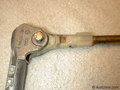
Stock shifter
|
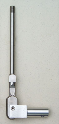
Stainless steel UUC short shifter
|
|