|
|
The VW Phaeton luxo-barge has a variety of standard front brake setups, one of which is of particular interest - the 365x34mm setup (not the same as the RS6 btw). This comes with a couple of nice features: * A better full-size backing plate than the ¾ size RS6 setup, and * A big air-scoop designed to work with wide, low profile tyres. This project is about adapting the Phaeton brake setup to the RS6. I have just completed this upgrade to my RS6. This post contains the detail of how I made the parts fit, with the objective that anyone with moderate skill would be able to accomplish the work. To start, you require the following parts 1) 2x Phaeton backing plates (3do 615 311c & 3d0 615 312c) 2) 2x Phaeton air ducts (3d0 615 447d & 3d0 615 448d) 3) 4x brake bolts (100 650 02) 4) 8x securing bolts (908 429 03) 5) A sheet of 4mm particle board 6) Some small 2mm mild steel pieces 7) A couple of 10mm (long shank) 3mm rivets (aluminium) 8) A 3mm drill and a 20mm borer. 9) Tools: Jigsaw, Welder, Knife, Drill, Socket set Stage 1 - Preparation Remove the road wheels, and access the brake system. Use a large screwdriver to force the pads back against the pistons a few mm. Don't go overboard here as you need to ensure that brake fluid doesn't overflow the reservoir. Now locate the rotor with a wheel bolt. I normally use the post from the toolkit to ease the job of removing the wheel and this is also useful to locate the rotor and stop it from turning. 1 more bolt is all you need to secure it. Use a hex head to remove the 2 M8 bolts that secure the callipers to the adapters. These are stretch bolts and will need to be replaced. I find it much easier to remove the calliper this way rather than to remove the adapter plate. However, if you remove the adapter plate, you do not have to replace the bolts. Make sure you have some stiff wire to hold the calliper. You should see something like this:  Stage 2 - Measurement and Cutting The Phaeton backing plates will not fully fit the RS6. There are a couple of issues we need to solve; The bottom of the strut sits proud of the plane of the securing bolts and the 4 bolts occupy slightly different positions in either car. To make the plate fit, we need to mask out the bottom of the strut. In order to do this, I used a simple technique involving thin cardboard which I secured using the backing plate bolts, and then using a sharp knife and scissors made the cardboard fit precisely.   Once you are happy with this, you need to get busy with your jigsaw. [If you are confident with your jigsaw skills, you can go straight to the stage of cutting out the backing plate, but I chose the intermediate step - partly as this was the 1st time, and I was unsure of the issues with the bolt holes.] Using the 4mm particle board, trace out the shape of the phaeton backing plate and make sure the fit is good. Now using the cardboard piece, make the cut-out into the particle board to the point where the particle board can be bolted up to the strut.  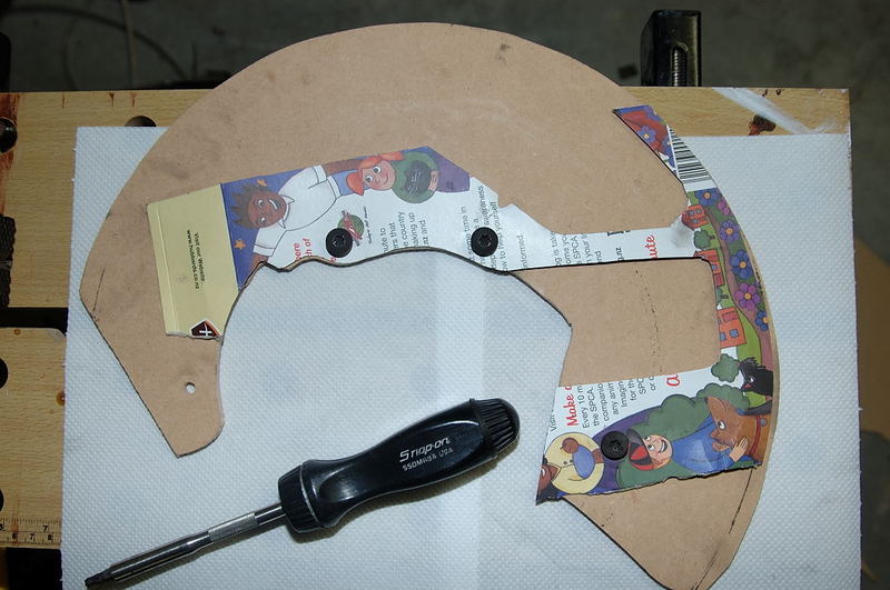  Note the top bolthole that doesn't match up. We will come to this shortly. Now that you have an accurate blank, you can get to work with your jigsaw (now with mild steel blades) and cut out the strut hole in the 1mm mild steel backing plate. This is not hard, and a little bit of care will result in a good job. You will need to elongate the bottom bolt hole somewhat in order to fit correctly. 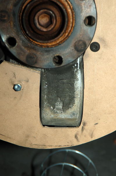   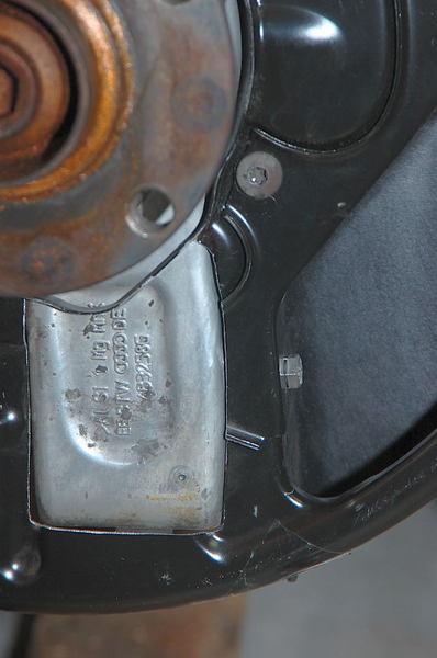 Stage 3 - Anal Retentives Anonymous I have mentioned that top bolt not being covered by the strut. You may not bother about this. The 3 remaining bolts secure the backing plate very well, and there is no need for the 4th bolt. Really. No really. Anyway, I wasn't happy about this and so made up a couple of pieces of 2mm mild steel to cover the holes and welded these to the backing plate. This is a relatively painstaking job, one which you could out-source to your local engineering shop or do with a bit of effort yourself. Don't forget to paint the end result to avoid issues with rust. I used 2mm plate against the 1mm backing plate as this lined up the vertical plane of the bolts holes after I had profiled the steel fillets. You will need to champher the pieces carefully to avoid blow-through when you weld. The end result, bolted up will look from this:  To this - all bolted up with 4 bolts:   Now re-assemble the brake assembly. The Allen bolts for the callipers need to be replaced with new (stretch) bolts and be torqued to 120nm. I used the 8 "backing plate" bolts to replace the 8 old ones (they come with lock-tight already on them), and use the old bolts to secure the scoops. These can be any M8 bolt, (I originally used stainless M8 Allen bolts), but I like the EOM bolts as they are low profile, and we care about aerodynamics (right)? Stage 4 - Clearance Now you have the backing plate secure, you only have 1 more issue to sort - the clearance of the scoop itself. It is 90% fine, height and width work well with the 19" wheel (and even better with the 18" one). However, on full lock, the bottom strut bolt will push the scoop against the backing plate - not all the way, but enough to be a bother. The plate itself is stronger than the original one, but you won't want this happening, if you are like me. You can do one of 3 things: a) Ignore it. Don't. b) Turn the strut bolts around (the nut faces forwards, use a new bolt to drive the old one out and have the bolt head facing front. This is quite straight-forward - remember to protect the track rod (behind) from the bolt head as you drive it out. Use a putty knife or something. Finally remember not to tighten the bolt (80nm) until the car has it's weight on the wheels (as the bush will twist otherwise). c) Cut a hole in the scoop to accommodate the bolt. This is the course of action I took. Mainly because turning the bolt around doesn't sort the clearance issue (it does make a difference, but not enough for me), and because the 20mm hole you require can be easily masked. I made careful note of the centre of the bolt where it impacted the scoop, and drilled a 20mm hole which, if you're careful is all you require for the nut to clear. If you're not careful enough, use a knife to carefully widen the hole to fit. Next I used a strip of thickish (2mm) rubber and a 3mm pop rivet to cover the front of the hole. This has the effect of prevent air moving through the hole, but moving aside for the strut bolt when required. See below the hole correctly situated to clear the bolt (look carefully and you will see the end of the bolt poking through the hole):  Below is the front view of the scoop and of the hole with the flap positioned and riveted.  Finally is the finished product from the rear of the scoop (suspension side) with the hole and the flap. 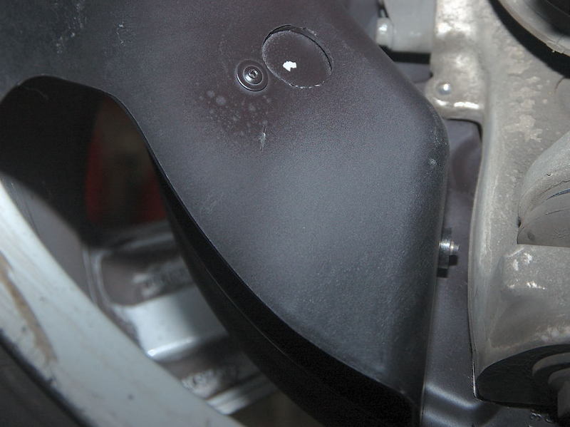 And last, but not least, here is the final result 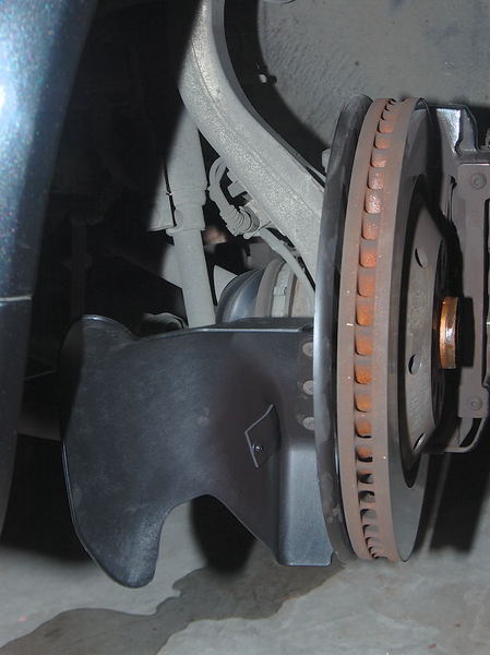 many thanks to jimmy s for tips and btdt! |
|
Advertising |
Contact Us |
Cookie Policy |
Privacy Statement |
Terms of Service |
Do Not Sell My Personal Information
© 2020 MH Sub I, LLC dba Internet Brands |