|
The controller is a pretty easy install but it does require a good deal of
time--plan on at least 4 hours to do it right. It requires mounting two
temperature sensors (ambient and intercooler), connecting a signal wire to one
of the injectors, the wiring for the pump along with a switched +12V and
ground. The controller comes with two labeled, ready-made harnesses which
were just about right for my install.
As always, if you attempt to modify your car be sure you possess the skill to do so. These instructions are only a guideline and do not include every
teeny-tiny detail. If you choose to do the mod you choose to do the mod. I'm not responsible in any way if damage your car.
Remember, if you must raise the vehicle always support it with jack stands...
never trust a jack.
|
 |
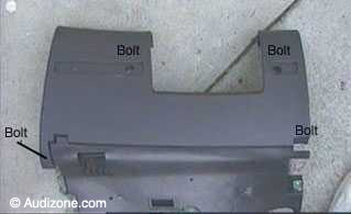
- Inside, remove the lower knee pad panel. 4 bolts -- 2 behind the hole plugs, one RH lower
corner and one behind the fuse box cover
- The plug covers just pop out if you use a small screwdriver to pry them out.
- Use the 8mm nut driver or socket to remove the bolts
- Pull the panel straight back then down
- When you drop the panel down be careful not to pull the diagnostic connector for the
computer - it looks (and is) fragile. Press the release tabs and it pops out.
|
 |
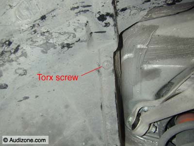
- Raise and support the car.
- Remove the left front wheel.
- Remove the T-25 Torx screws that secure the fender well.
|
 |
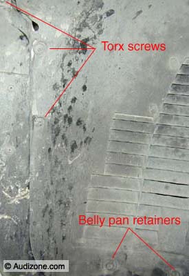
- Remove the remaining T-25 Torx screws that secure the fender well and the two
1/4 turn retainers that secure the bottom of the fender well to the
belly pan.
- You don't have to completely remove the fender well. With
enough of the Torx screws removed you can semi-fold the liner out of
the way. It does enjoy springing back into place and whacking
you in the head from time to time. After getting whacked in the
head twice I
zip-tied the little bastard back and out of the way.
|
 |
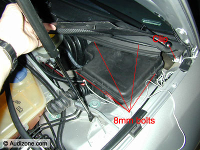
- To run the wiring harness inside the car I took advantage of the
opening into interior afforded by the plastic enclosure that
houses the ECU.
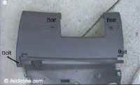
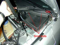
- Remove the trim panel at the firewall (pull the rubber weatherstrip
forward to remove) and slide it out. 5 - 8mm bolts secure the cover for the
ECU enclosure.
- For easier access to the rear bolt remove the clip near
the hood hinge... just be careful not send it flying off into
the dark recesses of the engine bay.
|
 |
- I made a small hole in the rubber grommet for the new harness and
sealed it with silicone sealant.
|
 |
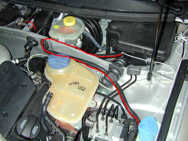
- The route I used for the new harness.
|
 |
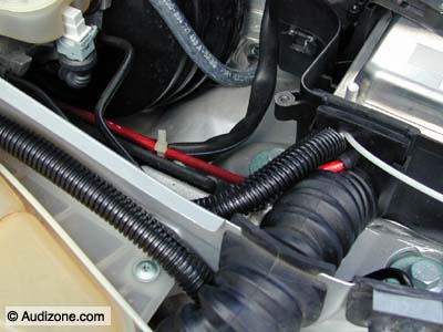
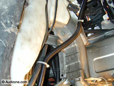
- With the harness running between the body and the washer jug it
continues down into the inner fender just behind the intercooler.
|
 |
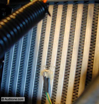
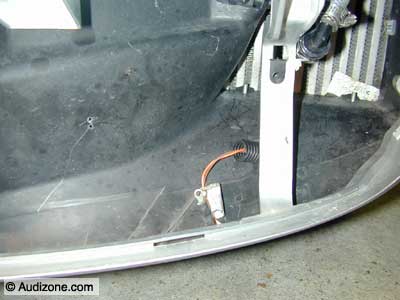
- Gently spread two of the fins on intercooler and slide the
intercooler sensor
into the intercooler. Note that the sensor must be mounted on
the back of the intercooler.
- Apply a dab of adhesive to secure the sensor being certain not to
get any on the sensor or it will slow the sensors response time to
temperature changes.
|
 |
- Remove the intercooler grill by pulling on it on the end closest to
the middle of the car. When the end pops out slide the grill slightly
toward the middle of the car then pull out the other end.
- Route the ambient sensor underneath the front air ductwork.
Luckily, a hole exists to pass the wire through.
- I drilled two small holes and secured the sensor harness with a zip
tie and a dab of adhesive.
|
 |
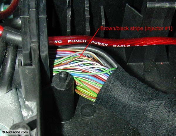
- Now for the scary part of the install. You need to attach a wire to
the (+) side of a fuel injector. I chose injector #1 for no good
reason other than it was the first wire I identified while digging
around in the wiring harness.
- Before proceeding I disconnected the ECU to prevent damage in the
event I did something stupid. No-cost insurance.
- Find the thin Brown/Black striped wire and gently strip off a
section of insulation. Don't cut the wire!! Verify that
you have the correct wire with an ohmmeter at the injector connector
and your bare wire. Note: The wiring harness colors
changed after the 2000 model year. Choose an injector (any will do,
does not have to be #1), determine the wire colors then verify you
have the right wires further up the harness with an ohmmeter.
- Now carefully solder the injector signal lead to the injector wire
and secure with electrical tape.
- Route the controller side of the harness inside the car through the
access hole under the ECU.
|
 |
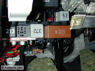
- The second harness has ground, +12V and the pump power connections.
- I connected the controller pump power to the power wire for the headlight washer pump behind
the brown relay, #389.
- Pull out relay 389.
|
 |
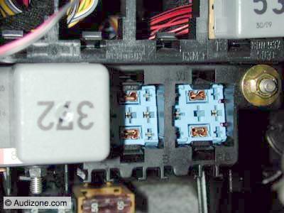
- Once you pull the relay out release the 4 tabs on the blue connector
and push it out of the carrier.
|