When you click on links to various merchants on this site and make a purchase, this can result in this site earning a commission. Affiliate programs and affiliations include, but are not limited to, the eBay Partner Network.
Hi all, first time posting so be gentle with me please and Apologies for the extensively long post.
I�ve recently fitted one of these 10.25� android screens to my Q5 and everything seemed to be good until trying to play audio. The system needs the source to be set to external aux which should have been achieved by connecting the provided AMI to 3.5mm jack adaptor to the Ami port and then to the audio out coming from the new screen BUT after plugging in everything the source menu says �AMI no device connected� and it�s driving me potty. Below are all the things I�ve tried:
1) checked all connections multiple times - all good
2) ensured everything is in the correct place - all good
3) checked no connectors are loose, damaged or broken - all good
4) checked all pins to make sure none are squashed, bent or missing - all good
5) Ami cable has a 1k ohm resistor between pin 21 and 22 which should auto-select aux when plugged in (which it doesn�t)
6) Tried another Ami to male 3.5mm jack also didn�t work
6) checked continuity of all the cabling back to the new screen - all good
7) checked all settings on both new system and original MMI - all good
8) checked all fuses on both car and new system - all good
After all this and still no joy. But now the big twist! I reinstalled my old Apple CarPlay module which is connected to the original 8.8� display and after making all the connections the external aux connection was grey�until I plugged in the same Ami cable and it switched on and everything worked 100% fine.
Has anyone got any ideas as it�s driving me bananas. Have spent so many hours trying to troubleshoot this issue but now i�m stuck!!!
I�m wondering if I need to enable the green menu which currently doesn�t work on my car and then properly switch on the aux input but why does my old system switch it on and the new one not!
It's not about the green menu. This is an MMI 3G vehicle or a Concert radio vehicle? AMI for Concert is very differently managed vs MMI 3G. This sounds familiar, but can't recall the other thread.
So "what's different"? It's all the same except the "man-in-the-middle" harness you install between the factory harness quad-block plug and the J794 (going to assume this is an MMI 3G config)? I don't have an AMI AUX cable to test, but I assume the only wired pins on it are 1 to tip, 2 to ring, 3 to sleeve, 4 is the shield, then resistor across 21 to 22. 21 goes back to T12y pin 6 (orange); 22 goes back to T4ap pin 4 (brown). The ground on 22 is shield wrapped with iPod detect on 16 (orange), USB data+ on 17 (blue), and USB data- on 18 (green). These four go together to the HSD jack. Unclear what 9 (violet, to T12y pin 5) is for. J794 info says unassigned.
Assuming the third-party devices are not interacting with the HSD jack which connects 22 back to the J794 (the yellow one), that path is likely unchanged. And if it's the same AMI cable, that's unchanged. So what changed? The connection from green pin 6 on the J794 to pin 21 on the AMI port.
Take the working config, unplug whatever is directly plugged into the J794, unplug the AMI cable on the AMI port, then test resistance value from green pin 6 on the whatever plugs into the J794 to the pin 21 on the AMI port. Then swap out for the other materials, test again. Is there an issue getting pin 21 to pin 6, open circuit, high resistance, flaky consistency, etc.
Hi SMac770, really appreciate your reply. Yes it�s an MMI 3G and just to clarify when you say green pin 6 you�re referring to pin 6 of the green connector which is part of the quad lock connector that goes into the back of the J794 unit? If so I�ll check the continuity and resistance of that connection and if it�s over 18.7k i suppose that would be why it�s not switching to aux right? If this wire is not connected for whatever reason then that�s the smoking gun. If it is connected with little to no resistance could it be the actual screen?
Thanks
Yeah, pin 6 on the green 12-pin. I don't know what you mean by screen. There's no reason for that wire to be getting routed to the screen. The vehicle harness plugs into "side A" of the aftermarket harness, then "side B" of the aftermarket harness plugs into the J794. Ie, man in the middle. The aftermarket harness is there to tap the normal communications between the car systems and the J794, particularly between the E380 controls and the J794. The J794 to screen is a complete different cable. That cable would go to the Android tablet, since the tablet is replacing the factory screen. Now, why the aftermarket device doesn't simply drop it's own analog audio output onto the "side B" in place of the AUX lines coming into the "side A", no idea. Would seem easier than having to route a cable from tablet AUX port to the AMI AUX port. But I have no idea how the aftermarket device is actually wired regarding the wires on the green 12-pin.
Just checked and unfortunately looks like green pin 6 resistance is 0.8ohms measured from connector that goes into the j794 through the piggy back connector and to pin 21 of the ami port. This is using the both the non-working setup and the working setup
i traced the green pin 6 wire as it splits mid-loom and followed that up to one of the connectors going into the screen. This also had good continuity and was not high resistance.
This is driving me to madness. I might just reinstall the old CarPlay box and send this other one back.
Sorry when i say screen it�s the android tablet part. The green pin six is plugged into the back of that as well as going to pin 21 of the ami port so I�m trying to see if i can temporary remove that pin from the connector and see if that makes a difference somehow
Yeah, can't say. But that you say the wire "splits" would seem odd. I would expect the intermediate harness (for tablet) to just directly connect green pin 6 on the vehicle harness side to straight through to green pin 6 on the plug into J794 side. If it's going off to the tablet itself, the tablet might be creating some issue on the line when it's operating. If it's adding some load in parallel, that's going to drop the net resistance value seen at the J794.
I assume the hideaway box solution uses a similar manner of intermediate harness? If you look at the routing of the green 6 wire on both intermediate harnesses, do they appear to do the same thing?
The hidden box solution has a similar harness but I�ve just traced green pin 6 and this does not branch off to anywhere else it simple connects straight to the Ami port pin 21. I�m half tempted to cut that wire going off to the Android tablet on the non-working system. I tried to pull it out the connector block at the back of the Android screen but I couldn�t get it out. Must try harder!!!
Another difference though is the hidden box tapped into the canbus power by piggy-backing a connector on the back of the ac control panel whereas the android screen version is routed into what I think is the body control module (remove glovebox and it�s on the side of the centre console with two connectors. One red one black - it piggy-backed into the red connector)
Any other ideas before I get the cutters out and chop that wire in a place where I can easily splice it back together should that not make a difference?
Many thanks for your help as well
This is an image of the external aux working with the hidden box system temporarily reinstalled to make sure I hadn�t blown anything up�the ami cable is simply plugged into the port and is not connected to anything and is just left dangling. The act of just plugging it in activates the aux source. I�ve obviously tried having it just dangling AND also plugging in the audio out from the android screen and neither of these options worked.
Now bashing head against wall as it seemed all too easy to install and for it to just work. While I was out measuring the resistance earlier I checked every part of the install again for the umpteenth time and all seems correct
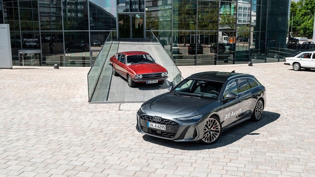
New Audi A6 Allroad Is The Market's Coolest Wagon: 9 Things to Know
Slideshow: Audi's latest A6 Allroad gets RS-style fenders, real off-road hardware, and enough personality to stand out in a market obsessed with crossovers.
Audi Recreates Crazy-Looking Speed Record Breaker From 1935
Slideshow: Audi has recreated one of the wildest machines of the pre-war speed-record era, reviving a streamlined V16 racer that originally exceeded 200 mph in 1935.