


This weekend's project....

Thread Starter
AudiWorld Super User
Joined: Nov 2000
Posts: 6,270
Likes: 0
I think I need to redo the lines, but I'm not quite sure how I should do it. The ports on the regulator are AN-6, but the fuel lines are 7.5mm, and the only fittings I could get are for 3/8 line (9.5mm) and trying to fit 7.5mm hose on a 3/8 barbed fitting is not fun.
<img src="http://johnbaas.dyndns.org/latest/fuelsys1_lo.jpg">
<img src="http://johnbaas.dyndns.org/latest/fuelsys2_lo.jpg">
<img src="http://johnbaas.dyndns.org/latest/fuelsys3_lo.jpg">
<img src="http://johnbaas.dyndns.org/latest/fuelsys1_lo.jpg">
<img src="http://johnbaas.dyndns.org/latest/fuelsys2_lo.jpg">
<img src="http://johnbaas.dyndns.org/latest/fuelsys3_lo.jpg">
Member
Joined: May 2001
Posts: 17,322
Likes: 0
fitting?<ul><li><a href="http://www.stockcarproducts.com/aqpindx.htm">http://www.stockcarproducts.com/aqpindx.htm</a</li></ul>

Elder Member
Joined: Sep 2002
Posts: 14,366
Likes: 1
The shop ended up cutting some of the hard fuel line to put the fittings on, IIRC they cut them back to where the 2 lines are mounted to the wall. This also allowed them to mount the regulator much higher on a metal mount so that the lines run staight to it. Once I get some pics of the setup I will have them posted, I will be going to the shop again tomorrow since today and tomorrow are my only days off.
BTW you might want to think about having the fuel feed line come in from the front and the closed end near the regulator, this way you will have more room for movement with the motor.
BTW you might want to think about having the fuel feed line come in from the front and the closed end near the regulator, this way you will have more room for movement with the motor.
Thread Starter
AudiWorld Super User
Joined: Nov 2000
Posts: 6,270
Likes: 0
and then loop back to the regulator. This would allow for movement, and let me move the regulator.
I didn't want to cut the stock plastic lines until I knew it worked correctly. Now that it's working, I'll consider cutting the lines, but I'd rather not if I don't have to.
I didn't want to cut the stock plastic lines until I knew it worked correctly. Now that it's working, I'll consider cutting the lines, but I'd rather not if I don't have to.

New Member
Joined: Apr 2001
Posts: 414
Likes: 0
be put in. And as for the S-afc by apexi i have everything wired up except for the throttle position sensor. I can figure out what pin/wirecolor i should connect it too. The wiring diagram is confusing me a lil bit  If you can please help me out i would greatly appreciate it. TIA
If you can please help me out i would greatly appreciate it. TIA
AudiWorld Stories
Bringing Audi to Life for Audi Fans

2027 Audi Q7 and SQ7: Audi Upgraded EVERYTHING!
Michael S. Palmer
Audi Unveils Absurdly Cool New Supercar: 10 Things You Need to Know!
Verdad Gallardo
The Highs & Lows of Every Audi C-Class Generation
Joe Kucinski
Top 10 Most Expensive Audis Ever Sold on Bring-A-Trailer
Brett Foote
10 Audi Features & Options We Miss the Most!
Joe Kucinski
Audi Recreates Crazy-Looking Speed Record Breaker From 1935
Verdad Gallardo
Coachbuilder Recreates the 1995 Audi TTS Concept
Verdad Gallardo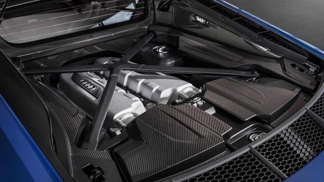
Every Audi V10 Car Ranked!
Joe Kucinski
9 Audi Designs That Aged Like Fine Wine
Verdad Gallardo
New Member
Joined: Mar 2000
Posts: 176
Likes: 0
This calibration just duplicates the old curve, which maxed the 440 injectors by 5000 rpm and 18 psi?
Did you get any wide band data from that dyno run?
The blue curve is based on a package that included chip, 440's, and 3" tube with A4 maf core. Hopefully chip made some changes to the load tables.
For the ss table, seems like you would want to now create a new target curve, mabe 25% more flow per volt vs the blue curve, and use 25% larger injectors. This would give 5.5V to ecu, based on 4.5V from Ford MAF at 1200 flow. This would be about 400 hp. New FPR could be trimmed for quick global changes.
Since load tables will be depressed scaled down MAF output, should not make inj's any bigger than needed.
Thread Starter
AudiWorld Super User
Joined: Nov 2000
Posts: 6,270
Likes: 0
No sense in making changes if I can't get the Ford MAF to act like the stock MAF.
I wasn't able to get any wideband readings on the dyno, but I have a LM-1 wideband unit arriving today.
I'm thinking I can slowly raise the fuel pressure, maybe 5%, then 10% and see how it runs. If there aren't any problems, then I'll look for larger injectors, and lower the pressure and start at 10%, 15%, etc...