
 07-20-2016, 10:51 AM
Last edit by: IB Advertising
See related guides and technical advice from our community experts:
- Audi A6 C6 How to Replace Fuel Pressure Sensor<br>Step by step instructions for do-it-yourself repairs.

Fuel Supply Sensor Fault?
12-22-2012, 04:09 PM
#1
AudiWorld Member
Thread Starter

Ran the vagcom and got the following fault:
1 Fault Found:
00438 - Fuel Supply Sensor 2 (G169)
010 - Open or Short to Plus - Intermittent
Freeze Frame:
Fault Status: 00101010
Fault Priority: 7
Fault Frequency: 16
Reset counter: 116
Mileage: 111139 km
Time Indication: 0
Date: 2012.10.28
Time: 17:53:41
Any idea what this means?
Thanks!
1 Fault Found:
00438 - Fuel Supply Sensor 2 (G169)
010 - Open or Short to Plus - Intermittent
Freeze Frame:
Fault Status: 00101010
Fault Priority: 7
Fault Frequency: 16
Reset counter: 116
Mileage: 111139 km
Time Indication: 0
Date: 2012.10.28
Time: 17:53:41
Any idea what this means?
Thanks!
 12-23-2012, 12:36 AM
#2
AudiWorld Senior Member
Ran the vagcom and got the following fault:
1 Fault Found:
00438 - Fuel Supply Sensor 2 (G169)
010 - Open or Short to Plus - Intermittent
Freeze Frame:
Fault Status: 00101010
Fault Priority: 7
Fault Frequency: 16
Reset counter: 116
Mileage: 111139 km
Time Indication: 0
Date: 2012.10.28
Time: 17:53:41
Any idea what this means?
Thanks!
1 Fault Found:
00438 - Fuel Supply Sensor 2 (G169)
010 - Open or Short to Plus - Intermittent
Freeze Frame:
Fault Status: 00101010
Fault Priority: 7
Fault Frequency: 16
Reset counter: 116
Mileage: 111139 km
Time Indication: 0
Date: 2012.10.28
Time: 17:53:41
Any idea what this means?
Thanks!
Found this TSB - http://uberlame.com/a6_tsb/Fuel%20Issues/Fuel%20Pressure%20Sensor%20(2).pdf
12-23-2012, 12:52 AM
#3
AudiWorld Senior Member
Ran the vagcom and got the following fault:
1 Fault Found:
00438 - Fuel Supply Sensor 2 (G169)
010 - Open or Short to Plus - Intermittent
Freeze Frame:
Fault Status: 00101010
Fault Priority: 7
Fault Frequency: 16
Reset counter: 116
Mileage: 111139 km
Time Indication: 0
Date: 2012.10.28
Time: 17:53:41
Any idea what this means?
Thanks!
1 Fault Found:
00438 - Fuel Supply Sensor 2 (G169)
010 - Open or Short to Plus - Intermittent
Freeze Frame:
Fault Status: 00101010
Fault Priority: 7
Fault Frequency: 16
Reset counter: 116
Mileage: 111139 km
Time Indication: 0
Date: 2012.10.28
Time: 17:53:41
Any idea what this means?
Thanks!
<TABLE cellSpacing=0 cellPadding=0 width="100%"><TBODY><TR><TD class=spalte-text><TABLE class="cc abstand-kap einzug-standard"><TBODY><TR><TD class=titel-kap>Checking fuel gauge sender 2 -G169-</TD></TR></TBODY></TABLE><TABLE class="cc abstand-standard einzug-standard"><TBODY><TR><TD class=wz-liste-kopf>Special tools and workshop equipment required</TD></TR></TBODY></TABLE></TD><TD class=spalte-pfeil></TD><TD class=spalte-marg></TD></TR></TBODY></TABLE><TABLE cellSpacing=0 cellPadding=0 width="100%"><TBODY><TR><TD class=spalte-text><TABLE class="cc abstand-standard einzug-standard "><TBODY><TR><TD class=einzug-liste>t </TD><TD>Hand-held multimeter -V.A.G 1526D-</TD></TR></TBODY></TABLE>
<TABLE class="cc abstand-liste einzug-standard "><TBODY><TR><TD class=einzug-liste>t </TD><TD>Auxiliary measuring set -V.A.G 1594C-</TD></TR></TBODY></TABLE>
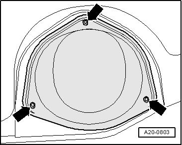
<TABLE class="cc einzug-standard abstand-standard absatz-hervor"><TBODY><TR><TD>Procedure</TD></TR></TBODY></TABLE><TABLE class="cc einzug-standard abstand-standard "><TBODY><TR><TD class=einzug-liste>� </TD><TD>Remove rear seat bench</TD></TR></TBODY></TABLE><TABLE class="cc einzug-standard abstand-standard "><TBODY><TR><TD class=einzug-liste>� </TD><TD>Unscrew cover for flange (left-side) -arrows-.</TD></TR></TBODY></TABLE>
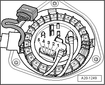
<TABLE cellSpacing=0 cellPadding=0 width="100%"><TBODY><TR><TD class=spalte-text><TABLE class="cc einzug-standard abstand-standard "><TBODY><TR><TD class=einzug-liste>� </TD><TD>Unplug electrical connector -arrow- at flange.</TD></TR></TBODY></TABLE>
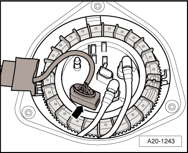
<TABLE cellSpacing=0 cellPadding=0 width="100%"><TBODY><TR><TD class=spalte-text><TABLE class="cc einzug-standard abstand-standard "><TBODY><TR><TD class=einzug-liste>� </TD><TD>Connect hand-held multimeter -V.A.G 1526D- to measure resistance between contacts -3- and -4-.</TD></TR></TBODY></TABLE><TABLE class="cc einzug-standard abstand-standard "><TBODY><TR><TD>With fuel gauge sender 2 -G169- installed:</TD></TR></TBODY></TABLE><TABLE class="cc abstand-standard einzug-standard "><TBODY><TR><TD class=einzug-liste>l </TD><TD>Sender at lower stop: approx. 790 � 975 Ω.</TD></TR></TBODY></TABLE><TABLE class="cc abstand-liste einzug-standard "><TBODY><TR><TD class=einzug-liste>l </TD><TD>Sender at upper stop: approx. 50 � 86 Ω.</TD></TR></TBODY></TABLE>
</TD></TR></TBODY></TABLE>
Note<TABLE class="cc abstand-liste-erster einzug-standard hinweis-rumpf"><TBODY><TR><TD class=einzug-liste>t </TD><TD>If the resistance is 0 Ω, there is a short circuit. If the resistance is ∞ Ω, there is an open circuit in the wiring.</TD></TR></TBODY></TABLE><TABLE class="cc abstand-liste einzug-standard hinweis-rumpf"><TBODY><TR><TD class=einzug-liste>t </TD><TD>In order to test the maximum and minimum values for �tank full� and �tank empty�, remove the fuel gauge sender 2 -G169- and move the float all the way to its top or bottom position.</TD></TR></TBODY></TABLE><TABLE class="cc abstand-liste einzug-standard hinweis-rumpf"><TBODY><TR><TD class=einzug-liste>t </TD><TD>The following values are obtained with the fuel gauge sender removed, due to the greater travel of the float arm:</TD></TR></TBODY></TABLE>
</TD></TR></TBODY></TABLE>
<TABLE class="cc einzug-standard abstand-standard "><TBODY><TR><TD>With fuel gauge sender 2 -G169- removed:</TD></TR></TBODY></TABLE><TABLE class="cc abstand-standard einzug-standard "><TBODY><TR><TD class=einzug-liste>l </TD><TD>Sender at lower stop: approx. 1004 Ω.</TD></TR></TBODY></TABLE><TABLE class="cc abstand-liste einzug-standard "><TBODY><TR><TD class=einzug-liste>l </TD><TD>Sender at upper stop: approx. 50 Ω.</TD></TR></TBODY></TABLE><TABLE class="cc einzug-standard abstand-standard "><TBODY><TR><TD>Assembly is carried out in the reverse order</TD></TR></TBODY></TABLE>
</TD></TR></TBODY></TABLE>
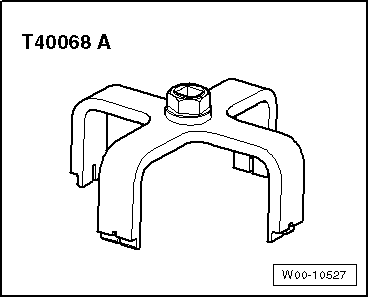
<TABLE cellSpacing=0 cellPadding=0 width="100%"><TBODY><TR><TD class=spalte-text><TABLE class="cc abstand-kap einzug-standard"><TBODY><TR><TD class=titel-kap>Removing and installing fuel gauge sender 2 -G169-</TD></TR></TBODY></TABLE><TABLE class="cc abstand-standard einzug-standard"><TBODY><TR><TD class=wz-liste-kopf>Special tools and workshop equipment required</TD></TR></TBODY></TABLE></TD><TD class=spalte-pfeil></TD><TD class=spalte-marg></TD></TR></TBODY></TABLE><TABLE cellSpacing=0 cellPadding=0 width="100%"><TBODY><TR><TD class=spalte-text><TABLE class="cc abstand-standard einzug-standard "><TBODY><TR><TD class=einzug-liste>t </TD><TD>Union nut tool -T40068 A-</TD></TR></TBODY></TABLE>
WARNING<TABLE class="cc einzug-standard abstand-liste-erster achtung-rumpf"><TBODY><TR><TD>Large amounts of fuel can escape.</TD></TR></TBODY></TABLE><TABLE class="cc abstand-standard einzug-standard achtung-rumpf"><TBODY><TR><TD>The fuel tank must not be more than <SUP class=hochtief>1</SUP>/<SUB class=hochtief>4</SUB> full when removing the fuel gauge sender 2 -G169-, otherwise a large amount of fuel will escape. Drain fuel tank if necessary; </TD></TR></TBODY></TABLE>
</TD></TR></TBODY></TABLE><TABLE class="cc einzug-standard abstand-standard "><TBODY><TR><TD class=einzug-liste>� </TD><TD>Briefly open filler cap for fuel tank and close again.</TD></TR></TBODY></TABLE><TABLE class="cc einzug-standard abstand-standard "><TBODY><TR><TD class=einzug-liste>� </TD><TD>Remove rear seat bench</TD></TR></TBODY></TABLE><TABLE class="cc einzug-standard abstand-standard "><TBODY><TR><TD class=einzug-liste>� </TD><TD>Detach cover for flange (left-side) -arrows-.</TD></TR></TBODY></TABLE>

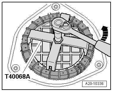
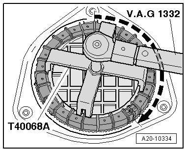
<TABLE class="cc einzug-standard abstand-standard "><TBODY><TR><TD class=einzug-liste>� </TD><TD>Use union nut tool -T40068 A- to unscrew union nut (left-side) -arrow-.</TD></TR></TBODY></TABLE>
Note<TABLE class="cc abstand-liste-erster einzug-standard hinweis-rumpf"><TBODY><TR><TD>The plastic detent on the threaded ring will break off when the union nut is unscrewed - this can be disregarded.
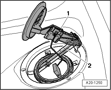
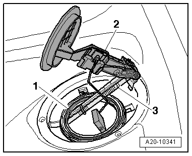
<TABLE class="cc einzug-standard abstand-standard "><TBODY><TR><TD class=einzug-liste>� </TD><TD>Carefully pull fuel gauge sender 2 -G169--item 1- and suction-jet pump -2- towards left, out of opening in fuel tank.
Note<TABLE class="cc abstand-liste-erster einzug-standard hinweis-rumpf"><TBODY><TR><TD>Make sure you do not bend float arm of fuel gauge sender 2 -G169- when removing suction-jet pump.
</TD></TR></TBODY></TABLE>
</TD></TR></TBODY></TABLE>
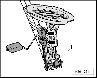
<TABLE cellSpacing=0 cellPadding=0 width="100%"><TBODY><TR><TD class=spalte-text><TABLE class="cc einzug-standard abstand-standard "><TBODY><TR><TD class=einzug-liste>� </TD><TD>Unclip suction-jet pump from flange.</TD></TR></TBODY></TABLE><TABLE class="cc einzug-standard abstand-standard "><TBODY><TR><TD class=einzug-liste>� </TD><TD>Unplug electrical connector -1-.</TD></TR></TBODY></TABLE><TABLE class="cc einzug-standard abstand-standard "><TBODY><TR><TD class=einzug-liste>� </TD><TD>Use screwdriver to release retaining tabs -arrows- and detach fuel gauge sender 2 -G169-.
</TD></TR></TBODY></TABLE></TD></TR></TBODY></TABLE>
</TD></TR></TBODY></TABLE>
<TABLE class="cc einzug-standard abstand-standard absatz-hervor"><TBODY><TR><TD>Installing</TD></TR></TBODY></TABLE><TABLE class="cc einzug-standard abstand-standard "><TBODY><TR><TD>Installation is carried out in the reverse order; note the following:</TD></TR></TBODY></TABLE>Note<TABLE class="cc abstand-liste-erster einzug-standard hinweis-rumpf"><TBODY><TR><TD>Renew seal and union nut.</TD></TR></TBODY></TABLE>
<TABLE class="cc einzug-standard abstand-standard "><TBODY><TR><TD class=einzug-liste>� </TD><TD>Insert fuel gauge sender 2 -G169- into guides on flange and press in until it engages.</TD></TR></TBODY></TABLE><TABLE class="cc einzug-standard abstand-standard "><TBODY><TR><TD class=einzug-liste>� </TD><TD>Plug in electrical connector and check that it has engaged properly.</TD></TR></TBODY></TABLE>
<TABLE class="cc einzug-standard abstand-standard "><TBODY><TR><TD class=einzug-liste>� </TD><TD>Clip suction-jet pump -3- onto flange -2-, so that you hear it click into place.</TD></TR></TBODY></TABLE><TABLE class="cc einzug-standard abstand-standard "><TBODY><TR><TD class=einzug-liste>� </TD><TD>Make sure that fuel supply line is connected to supply pipe for suction-jet pump with at least 3 cable ties.
Note<TABLE class="cc abstand-liste-erster einzug-standard hinweis-rumpf"><TBODY><TR><TD>When installing, make sure you do not bend float arm of fuel gauge sender 2 -G169-.</TD></TR></TBODY></TABLE><TABLE class="cc einzug-standard abstand-standard "><TBODY><TR><TD class=einzug-liste>� </TD><TD>Carefully insert fuel gauge sender 2 -G169- into opening in fuel tank.</TD></TR></TBODY></TABLE><TABLE class="cc einzug-standard abstand-standard "><TBODY><TR><TD class=einzug-liste>� </TD><TD>Slip new seal -1- over flange and insert it in groove on fuel tank.</TD></TR></TBODY></TABLE>
</TD></TR></TBODY></TABLE>
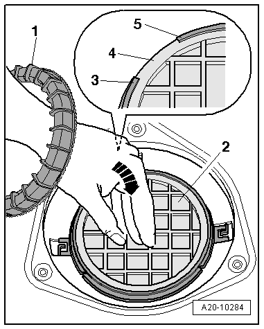
<TABLE cellSpacing=0 cellPadding=0 width="100%"><TBODY><TR><TD class=spalte-text><TABLE class="cc einzug-standard abstand-standard "><TBODY><TR><TD class=einzug-liste>� </TD><TD>Slip union nut -1- over your left arm and press flange -2- firmly into installation position -arrow- with your left hand.</TD></TR></TBODY></TABLE><TABLE class="cc abstand-standard einzug-standard "><TBODY><TR><TD class=einzug-liste>l </TD><TD>Lug -4- on flange must be between tabs -3- and -5- on threaded ring.</TD></TR></TBODY></TABLE>
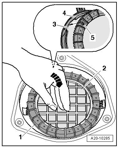
<TABLE cellSpacing=0 cellPadding=0 width="100%"><TBODY><TR><TD class=spalte-text><TABLE class="cc einzug-standard abstand-standard "><TBODY><TR><TD class=einzug-liste>� </TD><TD>Take union nut -1- off your left arm with your right hand and at the same time keep pressing down flange -2- firmly with your left hand -arrow-.</TD></TR></TBODY></TABLE><TABLE class="cc einzug-standard abstand-standard "><TBODY><TR><TD class=einzug-liste>� </TD><TD>Position union nut -1- with your right hand in such a way that double ridge -5- on ribs aligns with lug -3- of flange (approx. ten o'clock position). This will make union nut engage immediately with beginning of thread -4- when tightening.
</TD></TR></TBODY></TABLE></TD></TR></TBODY></TABLE>
<TABLE cellSpacing=0 cellPadding=0 width="100%"><TBODY><TR><TD class=spalte-text><TABLE class="cc einzug-standard abstand-standard "><TBODY><TR><TD class=einzug-liste>� </TD><TD>Keep pressing flange downwards firmly.</TD></TR></TBODY></TABLE><TABLE class="cc einzug-standard abstand-standard "><TBODY><TR><TD class=einzug-liste>� </TD><TD>Turn locking ring approx. 390� with your right hand until double ridge -1- is in approx. twelve o'clock position and at the same time keep on pressing flange downwards firmly with your left hand.
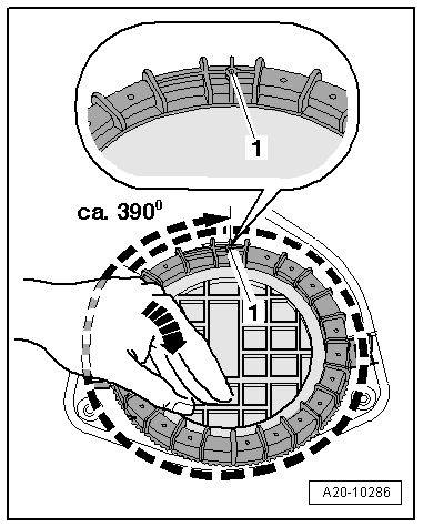
</TD></TR></TBODY></TABLE></TD></TR></TBODY></TABLE>
</TD></TR></TBODY></TABLE>
Caution<TABLE class="cc einzug-standard abstand-liste-erster achtung-rumpf"><TBODY><TR><TD>Take care to avoid leakage at flange.</TD></TR></TBODY></TABLE><TABLE class="cc abstand-standard einzug-standard achtung-rumpf"><TBODY><TR><TD>Press flange downwards firmly when tightening union nut to make sure flange does not also turn.
<TABLE class="cc einzug-standard abstand-standard "><TBODY><TR><TD class=einzug-liste>� </TD><TD>Use union nut tool -T40068 A- to tighten union nut for flange (left-side).</TD></TR></TBODY></TABLE><TABLE class="cc abstand-standard einzug-standard "><TBODY><TR><TD class=einzug-liste>l </TD><TD>Tightening torque: 120 Nm.</TD></TR></TBODY></TABLE>
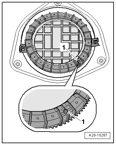
<TABLE class="cc abstand-standard einzug-standard "><TBODY><TR><TD class=einzug-liste>l </TD><TD>Checking: Double ridge -1- must now be aligned between five o'clock and six o'clock position.</TD></TR></TBODY></TABLE><TABLE class="cc einzug-standard abstand-standard "><TBODY><TR><TD class=einzug-liste>� </TD><TD>Install rear seat bench</TD></TR></TBODY></TABLE><TABLE class="cc einzug-standard abstand-standard "><TBODY><TR><TD class=einzug-liste>� </TD><TD>Put at least 5 litres of fuel into tank after installing fuel gauge sender 2 -G169-.</TD></TR></TBODY></TABLE>
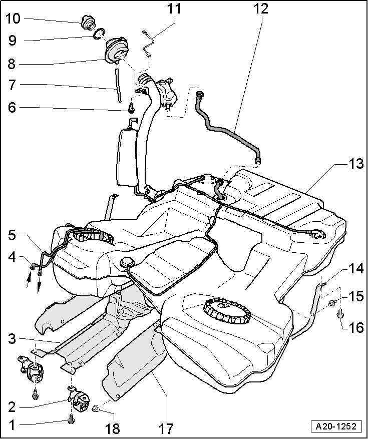
<TABLE class="cc abstand-kap einzug-standard"><TBODY><TR><TD class=titel-kap>Fuel tank with components - exploded view</TD></TR></TBODY></TABLE>
</TD></TR></TBODY></TABLE>
<TABLE class="cc abstand-standard erlaeutrg-explo"><TBODY><TR><TD class=einzug-nummer>1 - </TD><TD>Bolt</TD></TR></TBODY></TABLE><TABLE class="cc einzug-explo abstand-explo "><TBODY><TR><TD class=einzug-liste>q </TD><TD>23 Nm</TD></TR></TBODY></TABLE><TABLE class="cc abstand-standard erlaeutrg-explo"><TBODY><TR><TD class=einzug-nummer>2 - </TD><TD>Mounting for exhaust system</TD></TR></TBODY></TABLE><TABLE class="cc abstand-standard erlaeutrg-explo"><TBODY><TR><TD class=einzug-nummer>3 - </TD><TD>Support bracket</TD></TR></TBODY></TABLE><TABLE class="cc abstand-standard erlaeutrg-explo"><TBODY><TR><TD class=einzug-nummer>4 - </TD><TD>Fuel return pipe</TD></TR></TBODY></TABLE><TABLE class="cc einzug-explo abstand-explo "><TBODY><TR><TD class=einzug-liste>q </TD><TD>From fuel filter and fuel cooler</TD></TR></TBODY></TABLE><TABLE class="cc einzug-explo abstand-explo "><TBODY><TR><TD class=einzug-liste>q </TD><TD>Do not kink</TD></TR></TBODY></TABLE><TABLE class="cc einzug-explo abstand-explo "><TBODY><TR><TD class=einzug-liste>q </TD><TD>Clip onto fuel tank</TD></TR></TBODY></TABLE><TABLE class="cc abstand-standard erlaeutrg-explo"><TBODY><TR><TD class=einzug-nummer>5 - </TD><TD>Fuel supply pipe</TD></TR></TBODY></TABLE><TABLE class="cc einzug-explo abstand-explo "><TBODY><TR><TD class=einzug-liste>q </TD><TD>To fuel filter or supplementary fuel pump</TD></TR></TBODY></TABLE><TABLE class="cc einzug-explo abstand-explo "><TBODY><TR><TD class=einzug-liste>q </TD><TD>Do not kink</TD></TR></TBODY></TABLE><TABLE class="cc einzug-explo abstand-explo "><TBODY><TR><TD class=einzug-liste>q </TD><TD>Press release tab on pipe connector to disconnect</TD></TR></TBODY></TABLE><TABLE class="cc einzug-explo abstand-explo "><TBODY><TR><TD class=einzug-liste>q </TD><TD>Clip onto fuel tank</TD></TR></TBODY></TABLE><TABLE class="cc abstand-standard erlaeutrg-explo"><TBODY><TR><TD class=einzug-nummer>6 - </TD><TD>Bolt</TD></TR></TBODY></TABLE><TABLE class="cc einzug-explo abstand-explo "><TBODY><TR><TD class=einzug-liste>q </TD><TD>23 Nm</TD></TR></TBODY></TABLE><TABLE class="cc einzug-explo abstand-explo "><TBODY><TR><TD class=einzug-liste>q </TD><TD>Secures fuel filler neck and earth connection -item 11-</TD></TR></TBODY></TABLE><TABLE class="cc abstand-standard erlaeutrg-explo"><TBODY><TR><TD class=einzug-nummer>7 - </TD><TD>Overflow hose</TD></TR></TBODY></TABLE><TABLE class="cc einzug-explo abstand-explo "><TBODY><TR><TD class=einzug-liste>q </TD><TD>Attached at wheel housing liner</TD></TR></TBODY></TABLE><TABLE class="cc abstand-standard erlaeutrg-explo"><TBODY><TR><TD class=einzug-nummer>8 - </TD><TD>Rubber cup</TD></TR></TBODY></TABLE><TABLE class="cc abstand-standard erlaeutrg-explo"><TBODY><TR><TD class=einzug-nummer>9 - </TD><TD>Seal</TD></TR></TBODY></TABLE><TABLE class="cc einzug-explo abstand-explo "><TBODY><TR><TD class=einzug-liste>q </TD><TD>Renew if damaged</TD></TR></TBODY></TABLE><TABLE class="cc abstand-standard erlaeutrg-explo"><TBODY><TR><TD class=einzug-nummer>10 - </TD><TD>Filler cap</TD></TR></TBODY></TABLE><TABLE class="cc einzug-explo abstand-explo "><TBODY><TR><TD class=einzug-liste>q </TD><TD>Secured to tank flap</TD></TR></TBODY></TABLE><TABLE class="cc abstand-standard erlaeutrg-explo"><TBODY><TR><TD class=einzug-nummer>11 - </TD><TD>Earth connection</TD></TR></TBODY></TABLE><TABLE class="cc einzug-explo abstand-explo "><TBODY><TR><TD class=einzug-liste>q </TD><TD>To eliminate electrostatic charge</TD></TR></TBODY></TABLE><TABLE class="cc einzug-explo abstand-explo "><TBODY><TR><TD class=einzug-liste> </TD><TD></TD></TR></TBODY></TABLE><TABLE class="cc einzug-explo abstand-explo "><TBODY><TR><TD class=einzug-liste>q </TD><TD>Ensure that connector is seated properly and secure wire with securing bolt for fuel filler neck -item 6-</TD></TR></TBODY></TABLE><TABLE class="cc einzug-explo abstand-explo "><TBODY><TR><TD class=einzug-liste>q </TD><TD>After installing, use an ohmmeter to check electrical connection between metal ring on fuel filler neck and a bare metal part on body - Specification: approx. 0 Ω</TD></TR></TBODY></TABLE><TABLE class="cc abstand-standard erlaeutrg-explo"><TBODY><TR><TD class=einzug-nummer>12 - </TD><TD>Breather pipe</TD></TR></TBODY></TABLE><TABLE class="cc abstand-standard erlaeutrg-explo"><TBODY><TR><TD class=einzug-nummer>13 - </TD><TD>Fuel tank</TD></TR></TBODY></TABLE><TABLE class="cc einzug-explo abstand-explo "><TBODY><TR><TD class=einzug-liste> </TD><TD></TD></TR></TBODY></TABLE><TABLE class="cc abstand-standard erlaeutrg-explo"><TBODY><TR><TD class=einzug-nummer>14 - </TD><TD>Securing strap</TD></TR></TBODY></TABLE><TABLE class="cc abstand-standard erlaeutrg-explo"><TBODY><TR><TD class=einzug-nummer>15 - </TD><TD>Spreader clip</TD></TR></TBODY></TABLE><TABLE class="cc abstand-standard erlaeutrg-explo"><TBODY><TR><TD class=einzug-nummer>16 - </TD><TD>Bolt</TD></TR></TBODY></TABLE><TABLE class="cc einzug-explo abstand-explo "><TBODY><TR><TD class=einzug-liste>q </TD><TD>23 Nm</TD></TR></TBODY></TABLE><TABLE class="cc abstand-standard erlaeutrg-explo"><TBODY><TR><TD class=einzug-nummer>17 - </TD><TD>Heat shield for fuel tank</TD></TR></TBODY></TABLE><TABLE class="cc abstand-standard erlaeutrg-explo"><TBODY><TR><TD class=einzug-nummer>18 - </TD><TD>Nut</TD></TR></TBODY></TABLE><TABLE class="cc einzug-explo abstand-explo "><TBODY><TR><TD class=einzug-liste>q </TD><TD>2 Nm</TD></TR></TBODY></TABLE>
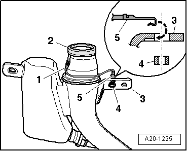
<TABLE class="cc bild-titel einzug-standard abstand-standard"><TBODY><TR><TD>Installation position of earth connection</TD></TR></TBODY></TABLE><TABLE class="cc einzug-standard abstand-standard "><TBODY><TR><TD class=einzug-liste>� </TD><TD>Route earth connection as shown in illustrations.</TD></TR></TBODY></TABLE><TABLE class="cc einzug-standard abstand-standard "><TBODY><TR><TD class=einzug-liste>� </TD><TD>First engage contact tab -5- of earth connection in mounting hole on fuel tank -3- and then press in spacer bush -4-.</TD></TR></TBODY></TABLE><TABLE class="cc einzug-standard abstand-standard "><TBODY><TR><TD class=einzug-liste>� </TD><TD>Ensure that connector -1- for earth connection is firmly seated on metal ring -2- on fuel filler neck.
</TD></TR></TBODY></TABLE>
WARNING<TABLE class="cc einzug-standard abstand-liste-erster achtung-rumpf"><TBODY><TR><TD>Risk of explosion caused by electrostatic discharge.</TD></TR></TBODY></TABLE><TABLE class="cc abstand-standard einzug-standard achtung-rumpf"><TBODY><TR><TD>After installation, use an ohmmeter to check the electrical connection between the metal ring on the fuel filler neck and a bare metal part on the body:</TD></TR></TBODY></TABLE><TABLE class="cc abstand-standard einzug-standard achtung-rumpf"><TBODY><TR><TD>Specification: approx. 0 Ω</TD></TR></TBODY></TABLE>
Last edited by royclark; 12-23-2012 at 01:44 AM.
The following users liked this post:
Pimmy (11-30-2021)
11-30-2021, 06:49 AM
#4

After not driving my car for a week, the fuel gauge suddenly stopped working, not moving from 0 (initially I thought someone drained my fuel while I was away).
This forum thread gave me very good pointers, thank you very much.
1. I am measuring 285 Ohm between contacts 3 and 4 on the fuel tank socket, while I have perhaps 1/4 of fuel in the tank.
2. I have inserted a 100 Ohm resistor between contacts 3 and 4 on the cable, but that made no difference to the fuel gauge.
3. I have removed and reinserted the Instrument Cluster fuse with no difference.
- Is my test (2.) valid? I am not sure if power should be applied to any of those pins to simulate the sensor.
- Does the above mean that the fuel sensor works OK and the problem is elsewhere (wires perhaps)?
- Can anyone tell me what is the purpose of each of the connectors 1-5 (wiring diagram would be amazing so that I can understand how to test better)?
- Any suggestions on how to proceed?
Thank you, Pimmy

Thread
Thread Starter
Forum
Replies
Last Post
Popsakadog84
2.0T FSI Discussion
0
04-02-2019 10:19 AM
Ste4lth
A8 / S8 (D3 Platform) Discussion
4
12-16-2018 07:53 AM