S5 Wheel Bearing Replacement DIY: Comprehensive Instructions (other B8 cars similar)
 11-29-2015, 02:18 PM
#1
AudiWorld Super User
Thread Starter

As our cars creep up in mileage, and we put heavy-*** wheels on them, wheel bearings are going to start to fail. I’m at 77K miles now, and this bearing has been groaning/humming for at least the last nine months (see
to hear how chewed up it was when I rotated it by hand). If your car has a noticeable rotational noise, one that increases with road speed but is independent of gearbox or engine speed, there’s a good chance it’s a dying wheel bearing. Mine got loud enough toward the end that it started to get annoying to listen to when driving. Time to go! I finally got around to fixing it today.
Below is a comprehensive instruction set for you if you’re tempted to DIY. If you have the tools, it’s pretty easy - it took me two hours from wheels up to wheels down, not counting travel time to the shop for a hydraulic press. You will need quite a few tools, including some non-standard drivers, so take note of what’s required (I’ve highlighted these below), but overall, it's not THAT challenging. The two main challenges are: the bolts will take a bit of force to remove while simultaneously trying to NOT strip-out the heads on the triple-square; and, the press fit of the hub into the bearing collar is a *tight* fit and absolutely requires a hydraulic press. This whole instruction set is for a 2008 S5 V8, but this procedure is going to be pretty similar across the B8 lineup, so these instructions will generally apply to A4/S4/Q5s as well (some bolts may be different).
Parts Needed (pics below)
1. Wheel bearing replacement kit. Most OER/aftermarket kits include the following:
- One wheel bearing and housing (OEM P/N: 4H0498625D)
- Four housing bolts (Torx T60), which must be replaced once removed (OEM P/N: WHT000237A)
- One center axle bolt (19mm hex), which also must be replaced once removed (OEM P/N: 8E0407643A)
There are lots of kits available, but I got one just like this: aftermarket wheel bearing kit.
2. Six 10mm triple-square/XZN differential flange/axle bolts that must be replaced once removed (OEM P/N N90441103). While these aren't torque-to-yield bolts, they are marked as "replace" in the service manual, so order new ones. They're cheap; $1.25 per bolt via GenuineAudiParts.com. These are NOT generally included in wheel bearing kits.
Tools Needed
- Torque wrench
- Impact wrench, air ratchet, and air compressor (NOT essential, but helpful if you're doing this by yourself)
- Ratchets, short and long extensions, adapters, and wobbly extensions - probably will need 1/4", 3/8", and 1/2"
- Breaker bar and long cheater bar (you'll be putting a ton of torque on the axle bolt)
- Mallet (to knock the wheel bearing and hub out of the spindle)
- Wire brush (to clean the spindle, axle splines, hub splines, driveshaft flange, and differential output flange)
- Paracord or rope (to hang the caliper from the upper control arms as you work)
- Paint pen or marker (to mark the bolts being torqued)
- 10mm socket or wrench (for the plastic axle shield)
- 17mm socket (for the wheel bolts)
- 19mm socket (for the brake caliper carrier bracket bolts)
- 19mm hex driver/socket (for the large outboard axle bolt.**Note that this is a large, uncommon size**)
- T27 Torx (for the brake rotor keeper screw)
- T30 Torx (for the brake heat shield)
- T60 Torx (for the wheel bearing housing/hub bolts. **Note that this is a large, uncommon size**)
- M10/10mm triple-square (for the differential output flange bolts)
- M12/12mm triple-square (also for the wheel bearing housing/hub bolts.**Note that this is a large, uncommon size**)
- Hydraulic press (to press the splined hub out of the old bearing and into the new one)
Torque Specs
Center axle/hub bolt (19mm female hex): 200Nm/147ft-lb +180 degrees [replace with new]
Bearing housing and hub assembly (four Torx T60): 80Nm/60ft-lb., plus 90 degrees [replace with new]
Axle to differential output flange (six triple-square 10mm): 70Nm/52ft-lb in a star-pattern [replace with new]
Brake caliper carrier bracket (two 19mm bolts): 92lb-ft.
Wheel bolts: 89lb-ft.
Steps:
1. Remove the wheel center caps and break the center axle/hub bolt loose. With the wheel resting on the ground under full weight, loosen the center axle/hub bolt using using the 19mm hex driver/socket. Loosen, but don't remove it yet.
2. Jack the car up and secure it properly, and remove the wheels. You need only jack the front of the car up for the front wheel bearings, and only remove the wheels for which you're doing bearings (you don't have to remove both sides).
3. Remove the plastic axle/driveshaft guide that's secured to the body of the car using the 10mm socket or wrench. It's a plastic nut, so take it easy on this guy.
4. Remove the brake calipers directly at the carrier bracket using the 19mm socket. The bolts are accessed from the inboard side/backside of the spindle. Before fully removing the bolts, feed the rope or paracord through the carrier bracket and tie it to the upper control arms - you don't want the caliper falling off with force and dangling from the brake lines. Once the caliper is removed, tie the caliper high and out of the way.
5. Remove the brake rotor retaining screw using the T27 Torx. If the rotor is frozen to the hub, use the mallet to bang it off. Be ready for the rotor to fall off suddenly, so put something under it to cushion the blow (instead of your feet). The wheel hub now sits exposed.
6. Remove the brake dust shield using the T30 Torx.
For the following two steps, you can change the order based on whether you have an assistant or not. If you DO have an assistant, do these steps before steps 4-5 and have your assistant stand on the brakes as you loosen the bolts on the rotating bits in 7-8. If you're doing it by yourself, follow the additional recommendations in the steps below.
7. Remove the large axle bolt using the 19mm hex driver/socket. This works best with the impact wrench, since you will likely just spin the whole axle using hand tools, and an impact wrench can blast the bolt off faster than the axle will spin. If the axle IS spinning, insert a 3/8" extension into one of the wheel bolt holes and use it to stop the rotation against the threads of one of the bearing housing bolts that are exposed in the spindle assembly. You'll replace this large axle bolt during reassembly.
8. Remove the six bolts that secure the axle to the differential output flange using the 10mm triple-square driver/socket and long extensions. Take special care to seat the driver into the bolt head securely and straight - triple-square is a total pain in the *** and can strip-out easily if you don't seat the driver dead-on straight. Clean the bolt heads out first if you have to.
The bolts can be accessed using two extensions; rotate the whole assembly to bring the bolts to where you can access them. As above, you can use a 3/8" extension to stop the hub and axle assembly from rotating as you put force on the bolts. Note that not only do you need to ensure that the driver is properly seated, you'll also have to really torque them to get them out. Take care as you do this.
9. Remove the axle. This will take a bit of finessing and contortion, but it'll come out at this point. Don't puncture the rubber boots.
10. Remove the wheel bearing housing and hub assembly using either the 12MM triple-square OR the Torx T60 driver to remove the four bolts on the inboard/backside of the spindle. There was a revision somewhere in the build date and the old bolts are triple-square; new bolts are Torx. If it's the triple-square, take care in the same way that you did with the bolts in Step 8, above. Torx is a lot more forgiving. This will also take some force.
11. Remove the hub and bearing carrier assembly. You may need to tap it out using the mallet. Put something under it to cushion the blow.
12. Press the hub out of the bearing bore. The hub itself has the inner splined shaft that inserts into the bore of the bearing. If you have a press, you'll probably know what you're doing. If you don't, bring it to a machine shop, auto shop, muffler shop, etc... someone who knows what to do.
13. Press the hub into the new bearing housing.
14. Clean the mating surfaces. Use wire brushes to clean the spindle bore, the differential output flange, the axle flange, and then carefully clean the splines on the axle and in the hub (also use a rag). When cleaning the spindle bore, be careful not to damage the wheel speed sensor - it's the little black plastic tab on the forward side of the bore. When cleaning the axle splines, plug the openings to the CV joint so you don't contaminate the inside with debris. It's important to clear the mating surfaces, particularly where you need to be sure the bolts are able to seat - and torque down - properly.
15. Mark the axle flange to keep track of tightening in a star pattern. Use the paint pen or marker to mark 1-6 next to the holes. 1-3-5-2-4-6, clockwise.
Reassembly time!
15. Reinstall the bearing housing and hub assembly with the new bearing into the spindle and secure it using the Torx T60 bolts. These are torque-to-yield bolts, so you'll be replacing them (they're shipped with the many available aftermarket/OER bearing kits). Torque these to 80Nm/60ft-lb., plus 90 degrees. Mark the bolts and the spindle with a paint pen to keep track of the 90-degree turn.
16. Reinstall the axle. Once you get it into place, install the center axle bolt so it's snug, but don't torque it yet.
17. Reinstall the six axle flange bolts torquing them to 70Nm/52ft-lb in a star-pattern. This is where the 1-6 markings come in handy. Torque the bolt #1, rotate the axle 180 degrees and torque #2, then rotate back to #3, etc.
18. Reinstall the brake dust shield. Probably no more than 10ft-lb. or so.
19. Reinstall the brake rotor. Torque the keeper screw to like 5 lb-ft. It's really just to hold the rotor from falling off when the caliper is removed.
20. Reinstall the brake caliper assembly. Torque the bolts to 92lb-ft.
21. Tighten the center axle bolt to 200Nm/147ft-lb +180 degrees. Use a breaker bar and a cheater bar to get this much torque down. I pulled the handle from one of my floor jacks and used that and it was *still* hard to get it to the proper torque. Two options to hold the hub stationary for this: either have someone stand on the brakes as you torque it down, or reinstall the wheel and tighten it with the wheel on the ground. I used the brakes, but I didn't have an assistant, so I jammed a piece of 2x2" between the brake pedal and the metal part of the seat bracket and moved the seat forward until the brake pedal was depressed firmly.
Done.
In pictures:
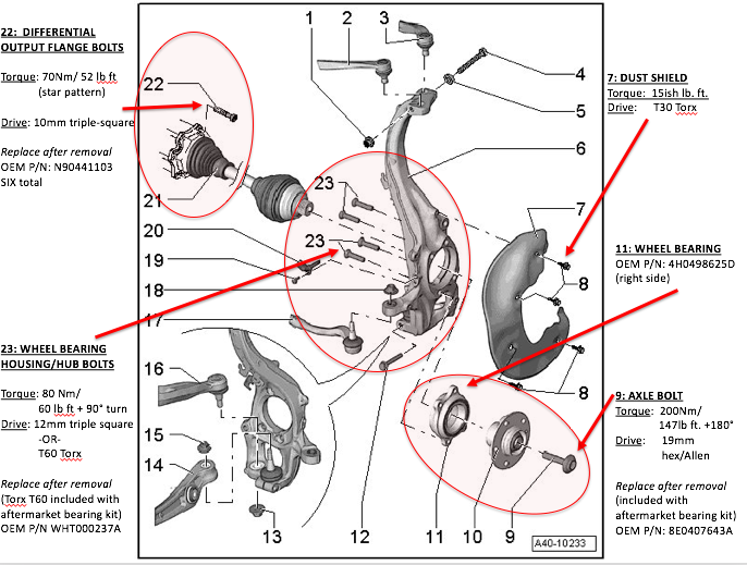
Schematic of the spindle, hub, and axle assemblies, with torque specs. This helps you visualize both what you will be doing, as well as the configuration of the parts.
(I) The bearing is pressed into the housing to form an assembly (#11) at the factory;
(II) the single-piece hub (#10) is pressed into the bearing’s bore;
(III) the mated bearing and hub assembly (red oval at lower right) is mounted to the outboard face of the spindle (#6), and secured with bolts (#23) from the inboard side of the spindle; and finally
(IV) the axle (#21) is installed and the center bolt (#9) secures the axle to the hub.
Wheel bearing kit including new bolts:

New bearing with original hub pressed-in:

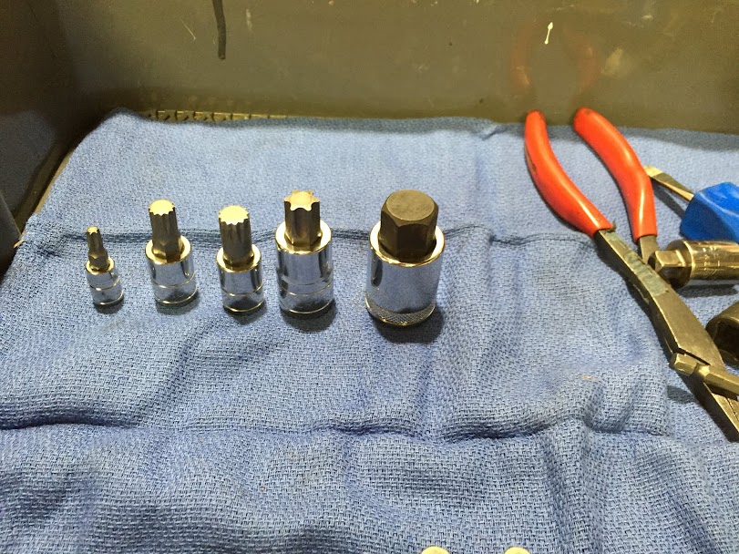
Non-standard drive bits required:
Wire brushing the axle flange with the axle in a vice:

Spindle with brakes and hub removed, after wire brushing:

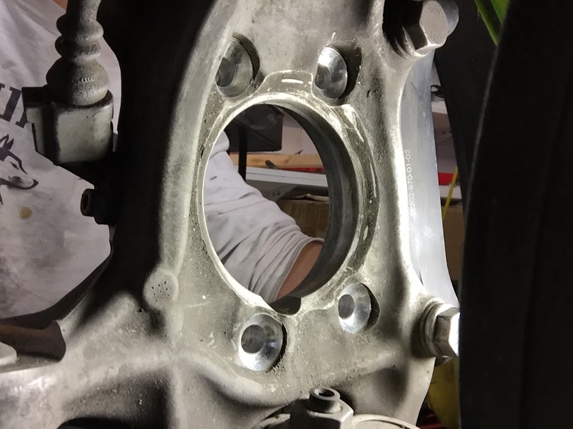
Differential output flange, looking through the spindle bore.

Backside/inboard of the spindle with all components removed. Wheel speed sensor is not shown in this pic:
Inboard side of the spindle with bearing housing reinstalled, and bolts tightened to 80Nm/60ft-lb., but before the final 90 degrees. Note the paint markings to keep track.

… and after 90-degree torquing. Note also the black tab at 10 o’clock - that’s the wheel speed sensor. Don’t break it.

Axle reattached to the diff output flange. Note the numbered markings to help keep track of the star pattern when re-torquing:

My cellulose assistant - a 2x2”, jammed against the metal part of the seat bracket to hold the pedal down while I torque the center bolt on the hub:

Cheater bar used to get the monster torque on the center bolt. That’s the whole handle from the floor jack:

Below is a comprehensive instruction set for you if you’re tempted to DIY. If you have the tools, it’s pretty easy - it took me two hours from wheels up to wheels down, not counting travel time to the shop for a hydraulic press. You will need quite a few tools, including some non-standard drivers, so take note of what’s required (I’ve highlighted these below), but overall, it's not THAT challenging. The two main challenges are: the bolts will take a bit of force to remove while simultaneously trying to NOT strip-out the heads on the triple-square; and, the press fit of the hub into the bearing collar is a *tight* fit and absolutely requires a hydraulic press. This whole instruction set is for a 2008 S5 V8, but this procedure is going to be pretty similar across the B8 lineup, so these instructions will generally apply to A4/S4/Q5s as well (some bolts may be different).
Parts Needed (pics below)
1. Wheel bearing replacement kit. Most OER/aftermarket kits include the following:
- One wheel bearing and housing (OEM P/N: 4H0498625D)
- Four housing bolts (Torx T60), which must be replaced once removed (OEM P/N: WHT000237A)
- One center axle bolt (19mm hex), which also must be replaced once removed (OEM P/N: 8E0407643A)
There are lots of kits available, but I got one just like this: aftermarket wheel bearing kit.
2. Six 10mm triple-square/XZN differential flange/axle bolts that must be replaced once removed (OEM P/N N90441103). While these aren't torque-to-yield bolts, they are marked as "replace" in the service manual, so order new ones. They're cheap; $1.25 per bolt via GenuineAudiParts.com. These are NOT generally included in wheel bearing kits.
Tools Needed
- Torque wrench
- Impact wrench, air ratchet, and air compressor (NOT essential, but helpful if you're doing this by yourself)
- Ratchets, short and long extensions, adapters, and wobbly extensions - probably will need 1/4", 3/8", and 1/2"
- Breaker bar and long cheater bar (you'll be putting a ton of torque on the axle bolt)
- Mallet (to knock the wheel bearing and hub out of the spindle)
- Wire brush (to clean the spindle, axle splines, hub splines, driveshaft flange, and differential output flange)
- Paracord or rope (to hang the caliper from the upper control arms as you work)
- Paint pen or marker (to mark the bolts being torqued)
- 10mm socket or wrench (for the plastic axle shield)
- 17mm socket (for the wheel bolts)
- 19mm socket (for the brake caliper carrier bracket bolts)
- 19mm hex driver/socket (for the large outboard axle bolt.**Note that this is a large, uncommon size**)
- T27 Torx (for the brake rotor keeper screw)
- T30 Torx (for the brake heat shield)
- T60 Torx (for the wheel bearing housing/hub bolts. **Note that this is a large, uncommon size**)
- M10/10mm triple-square (for the differential output flange bolts)
- M12/12mm triple-square (also for the wheel bearing housing/hub bolts.**Note that this is a large, uncommon size**)
- Hydraulic press (to press the splined hub out of the old bearing and into the new one)
Torque Specs
Center axle/hub bolt (19mm female hex): 200Nm/147ft-lb +180 degrees [replace with new]
Bearing housing and hub assembly (four Torx T60): 80Nm/60ft-lb., plus 90 degrees [replace with new]
Axle to differential output flange (six triple-square 10mm): 70Nm/52ft-lb in a star-pattern [replace with new]
Brake caliper carrier bracket (two 19mm bolts): 92lb-ft.
Wheel bolts: 89lb-ft.
Steps:
1. Remove the wheel center caps and break the center axle/hub bolt loose. With the wheel resting on the ground under full weight, loosen the center axle/hub bolt using using the 19mm hex driver/socket. Loosen, but don't remove it yet.
2. Jack the car up and secure it properly, and remove the wheels. You need only jack the front of the car up for the front wheel bearings, and only remove the wheels for which you're doing bearings (you don't have to remove both sides).
3. Remove the plastic axle/driveshaft guide that's secured to the body of the car using the 10mm socket or wrench. It's a plastic nut, so take it easy on this guy.
4. Remove the brake calipers directly at the carrier bracket using the 19mm socket. The bolts are accessed from the inboard side/backside of the spindle. Before fully removing the bolts, feed the rope or paracord through the carrier bracket and tie it to the upper control arms - you don't want the caliper falling off with force and dangling from the brake lines. Once the caliper is removed, tie the caliper high and out of the way.
5. Remove the brake rotor retaining screw using the T27 Torx. If the rotor is frozen to the hub, use the mallet to bang it off. Be ready for the rotor to fall off suddenly, so put something under it to cushion the blow (instead of your feet). The wheel hub now sits exposed.
6. Remove the brake dust shield using the T30 Torx.
For the following two steps, you can change the order based on whether you have an assistant or not. If you DO have an assistant, do these steps before steps 4-5 and have your assistant stand on the brakes as you loosen the bolts on the rotating bits in 7-8. If you're doing it by yourself, follow the additional recommendations in the steps below.
7. Remove the large axle bolt using the 19mm hex driver/socket. This works best with the impact wrench, since you will likely just spin the whole axle using hand tools, and an impact wrench can blast the bolt off faster than the axle will spin. If the axle IS spinning, insert a 3/8" extension into one of the wheel bolt holes and use it to stop the rotation against the threads of one of the bearing housing bolts that are exposed in the spindle assembly. You'll replace this large axle bolt during reassembly.
8. Remove the six bolts that secure the axle to the differential output flange using the 10mm triple-square driver/socket and long extensions. Take special care to seat the driver into the bolt head securely and straight - triple-square is a total pain in the *** and can strip-out easily if you don't seat the driver dead-on straight. Clean the bolt heads out first if you have to.
The bolts can be accessed using two extensions; rotate the whole assembly to bring the bolts to where you can access them. As above, you can use a 3/8" extension to stop the hub and axle assembly from rotating as you put force on the bolts. Note that not only do you need to ensure that the driver is properly seated, you'll also have to really torque them to get them out. Take care as you do this.
9. Remove the axle. This will take a bit of finessing and contortion, but it'll come out at this point. Don't puncture the rubber boots.
10. Remove the wheel bearing housing and hub assembly using either the 12MM triple-square OR the Torx T60 driver to remove the four bolts on the inboard/backside of the spindle. There was a revision somewhere in the build date and the old bolts are triple-square; new bolts are Torx. If it's the triple-square, take care in the same way that you did with the bolts in Step 8, above. Torx is a lot more forgiving. This will also take some force.
11. Remove the hub and bearing carrier assembly. You may need to tap it out using the mallet. Put something under it to cushion the blow.
12. Press the hub out of the bearing bore. The hub itself has the inner splined shaft that inserts into the bore of the bearing. If you have a press, you'll probably know what you're doing. If you don't, bring it to a machine shop, auto shop, muffler shop, etc... someone who knows what to do.
13. Press the hub into the new bearing housing.
14. Clean the mating surfaces. Use wire brushes to clean the spindle bore, the differential output flange, the axle flange, and then carefully clean the splines on the axle and in the hub (also use a rag). When cleaning the spindle bore, be careful not to damage the wheel speed sensor - it's the little black plastic tab on the forward side of the bore. When cleaning the axle splines, plug the openings to the CV joint so you don't contaminate the inside with debris. It's important to clear the mating surfaces, particularly where you need to be sure the bolts are able to seat - and torque down - properly.
15. Mark the axle flange to keep track of tightening in a star pattern. Use the paint pen or marker to mark 1-6 next to the holes. 1-3-5-2-4-6, clockwise.
Reassembly time!
15. Reinstall the bearing housing and hub assembly with the new bearing into the spindle and secure it using the Torx T60 bolts. These are torque-to-yield bolts, so you'll be replacing them (they're shipped with the many available aftermarket/OER bearing kits). Torque these to 80Nm/60ft-lb., plus 90 degrees. Mark the bolts and the spindle with a paint pen to keep track of the 90-degree turn.
16. Reinstall the axle. Once you get it into place, install the center axle bolt so it's snug, but don't torque it yet.
17. Reinstall the six axle flange bolts torquing them to 70Nm/52ft-lb in a star-pattern. This is where the 1-6 markings come in handy. Torque the bolt #1, rotate the axle 180 degrees and torque #2, then rotate back to #3, etc.
18. Reinstall the brake dust shield. Probably no more than 10ft-lb. or so.
19. Reinstall the brake rotor. Torque the keeper screw to like 5 lb-ft. It's really just to hold the rotor from falling off when the caliper is removed.
20. Reinstall the brake caliper assembly. Torque the bolts to 92lb-ft.
21. Tighten the center axle bolt to 200Nm/147ft-lb +180 degrees. Use a breaker bar and a cheater bar to get this much torque down. I pulled the handle from one of my floor jacks and used that and it was *still* hard to get it to the proper torque. Two options to hold the hub stationary for this: either have someone stand on the brakes as you torque it down, or reinstall the wheel and tighten it with the wheel on the ground. I used the brakes, but I didn't have an assistant, so I jammed a piece of 2x2" between the brake pedal and the metal part of the seat bracket and moved the seat forward until the brake pedal was depressed firmly.
Done.
In pictures:
Schematic of the spindle, hub, and axle assemblies, with torque specs. This helps you visualize both what you will be doing, as well as the configuration of the parts.
(I) The bearing is pressed into the housing to form an assembly (#11) at the factory;
(II) the single-piece hub (#10) is pressed into the bearing’s bore;
(III) the mated bearing and hub assembly (red oval at lower right) is mounted to the outboard face of the spindle (#6), and secured with bolts (#23) from the inboard side of the spindle; and finally
(IV) the axle (#21) is installed and the center bolt (#9) secures the axle to the hub.
Wheel bearing kit including new bolts:
New bearing with original hub pressed-in:
Non-standard drive bits required:
Wire brushing the axle flange with the axle in a vice:
Spindle with brakes and hub removed, after wire brushing:
Differential output flange, looking through the spindle bore.
Backside/inboard of the spindle with all components removed. Wheel speed sensor is not shown in this pic:
Inboard side of the spindle with bearing housing reinstalled, and bolts tightened to 80Nm/60ft-lb., but before the final 90 degrees. Note the paint markings to keep track.
… and after 90-degree torquing. Note also the black tab at 10 o’clock - that’s the wheel speed sensor. Don’t break it.
Axle reattached to the diff output flange. Note the numbered markings to help keep track of the star pattern when re-torquing:
My cellulose assistant - a 2x2”, jammed against the metal part of the seat bracket to hold the pedal down while I torque the center bolt on the hub:
Cheater bar used to get the monster torque on the center bolt. That’s the whole handle from the floor jack:
Last edited by Europa; 11-30-2015 at 08:24 AM. Reason: Clari

The following users liked this post:
findalex (08-14-2023)


Thread
Thread Starter
Forum
Replies
Last Post