Tour (II) Through a Modest (& Mostly OEM) Intake System; Intro...
#1
AudiWorld Senior Member
Thread Starter
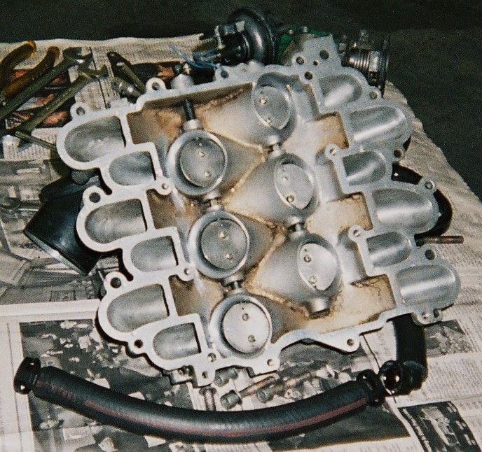
tubular_bells.jpg
...the effective (w)hole is greater than the $um of its' parts.
Intro & Overview:
Regarding a '93 90Q, here are 21 maintenance & mod. items which may collectively boost mileage & torque. Or they may not (YMMV)!
I am going to illustrate some items that may not usually be considered part of the Intake System because I find them useful when considering the Intake as a whole system. Taking several simple steps towards amongst other things, "tubular bells" (see above). A more efficient & low cost overall system is my goal.
I will attempt to expand each topic below in this thread as time permits. I invite you to check back here & welcome your comments & questions. I have questions of my own that perhaps you can help me with.
Certainly, many of these ideas are not new, nor mine, but I've included them as I like them.
Topics:
1. Radiator Grill;
2. Scoop behind Grill;
3. Bucket behind Headlight;
4. Filter-box Mounts;
5. Bucket to Filter-box Seal;
6. Filter-box Snorkel;
7. Filter-box Lid Clamps;
8. Filter-box Exit Velocity-stack (Mance's Mk. I);
9. "Restrictor-Plate" MAF;
10. OEM Noise Damper;
11. New OEM Rubber Gasket &; Telephone Cord Fix;
12. Non-"S" Throttle Body;
13. Throttle Body to Intake Manifold OEM Gasket, Synthetic Seal;
14. Intake Manifold,
15. Injector Re-cycle;
16. Injector Spray Clearance;
17. Vac. Lines &; Fuel Pressure Regulator;
18. EGR Solenoid;
19. Cam Cover Vents &; Hoses;
20. O2 Sensors; &
21. Odo/Tripmeter &; Trip Computer;
Organizing the Work &;
Conclusion: I will tell you straight away that I am very satisfied with the results of all of this, as the car runs better (faster, smoother & more economically) than I thought possible. Some questions and answers at the very end. More to follow. Tubular Bells (this is the music (by Mike Oldfield), I'm reminded of by the noise generated when doing the port-work of the Intake Manifold Workshop with abrasive paper spinning on the end of a high-speed mandrel...)
This is a 3rd redux of a thread originally done 03/10/2008. Sorry if I've deleted any posts you may have made there previously, but since "The Forum Change #1" the thread had become non-linear and largely un-readable. I have tried to incorporate the on-topic content of the previously posted questions I did receive. I am simply attempting to re-write the entire article so that it flows logically and hopefully is more comprehend-able. The above listed topics are now here in their original and correct numerical order. Unfortunately, after the re-write, "The Forum Change #2" deleted almost all the photos, which have (for now!) been restored.
Last edited by Lago Blue; 04-19-2020 at 06:10 AM. Reason: clarity
#2
AudiWorld Senior Member
Thread Starter
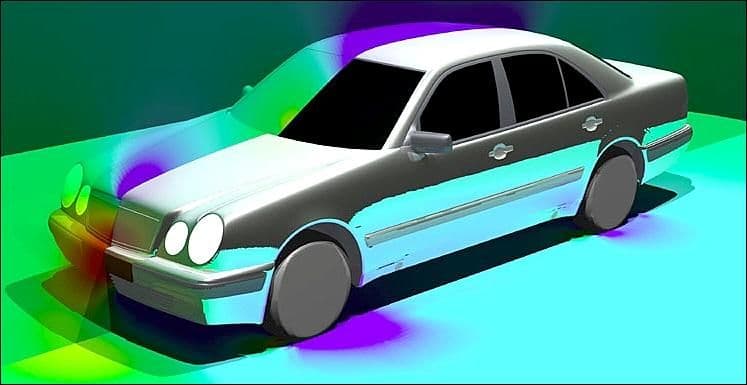
Pressure distribution illustrated here indicates our "red-zone" (just above the bumper) stock cold air intake (CAI) location is likely a good one.
"http://us1.webpublications.com.au/static/images/articles/i10/1023_9mg.jpg"
... modification; this is one of the last things I did.
Re. Siting a CAI; an excerpt from AutoSpeed magazine, an interesting article:
"At the front there must be a point above which the air goes over the car, and below which the air goes under the car. This is called the stagnation point, and it is here that there will be the greatest pressure developed on the front of the car as it moves forward. This graphic of a Mercedes shows the high-pressure stagnation area in red, lesser high-pressure areas in green, and the low-pressure areas in blue. (They're low pressure areas cos the airflow is being accelerated around a curved surface at each of those spots.)
And hey, that's all very well and good - but how do you find where the stagnation point is on your own car? And what if it's impossible to site the intake for a cold air duct there anyway? How do you rank the quality of other potential sites?"
More to follow.<ul><li><a href="http://autospeed.com/cms/A_1023/article.html?popularArticle">The complete article at Auto Speed...</a></li></ul>
Last edited by Lago Blue; 04-18-2020 at 12:18 PM.
#3
AudiWorld Senior Member
Thread Starter
1st photo below: Here is a photo that appears to show the location of the CAI on the IMSA 90Q. It appears to be in the stock location. You can see a another photo of the intake here:
http://www.audizine.com/gallery/data...d09_800_14.jpg
My question is: Was this location mandated by "the rules" or was it the free choice of the designer(s)?
Looking back at the Benz illustration (post above), it could perhaps be close to the very best spot.
BTW, those w/turbos may be interested to know that moving the CAI under the car...
(see 2nd photo below)
...fixed this annoying & hazardous problem (the bottom photo is the "before" shot, see also the "after" photo at link below).
The rear spoiler was now able to be trimmed back (it was eventually replaced by a much cleaner aerodynamically, bi-element wing), & consequently both top speed & fuel mileage where improved.
Yes, it was all quite embarrassing for Audi Gmbh, Ingolstadt had an image problem. Even though the fans loved it, the quattros where prancing around, not on four wheels but su due & to make matters worse, they where in effect; RWD!
How could they expect to sell Quattros, let alone FWD sedans Monday to Friday, if they where clearly racing RWD on the week-ends?
It had to be stopped & it was. The cars were eventually banned; the photos remain, but few details where ever revealed.
But now you know; the rest of the story of...
...Unintended Levitation.
Last edited by Lago Blue; 03-11-2020 at 06:52 AM.
#4
AudiWorld Senior Member
Thread Starter
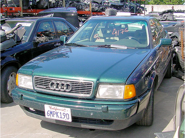
Mind the gap! (between bumper & the grill!)
Mine isn't quite as bad as this, but almost. You get the idea hopefully & this is much more iobvious to look at than my stock set-up.
After reading the post below, I filled this space with black foam weatherstrip because, whether there is air bleeding in here or being sucked out, it is not helping to get more pressure to the grill & the Cold Air Intake, I'm hoping that this will help to improve that.
"Air comes over the top of the front bumper like...".
Last edited by Lago Blue; 03-11-2020 at 06:54 AM.
#5
AudiWorld Senior Member
Thread Starter
b4_grill_1.jpg
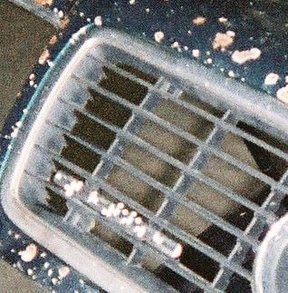
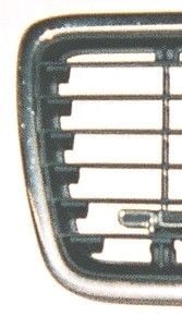
Grill opening just in front of the air-scoop.
1. Outboard Side: Flashing removed from the trailing edge of the "saw-tooth" area. This is right where the horizontal slats attach to the curved profile of the perimeter frame of black plastic.
I'm curious to know why this was made in this fashion, was it for strength; is it a vortex generator, maybe it helps the air through the narrow opening behind the headlight; or does it just make noise to help mask engine intake noise? Otherwise, it certainly looks to be made more complicated than it needs to be. It's quite different from the B3 grill, but very similar to the A4.
What I wanted to do was allow the air to leave the grill in a little cleaner fashion, so I removed the flashing with a little riffler file.
2. Horizontal Slats: here again, removed the flashing on the top sides (only) of the slats, the bottom side was found nicely rounded.
(photo to follow)
Last edited by Lago Blue; 04-18-2020 at 12:19 PM.
#6
AudiWorld Senior Member
Thread Starter
b4_grill_2.jpg
<center><img src="http://pictureposter.audiworld.com/124134/b4_grill_2.jpg"></center><p>
...I simply made smooth, by de-flashing, all the little "C" shapes along the left-hand side (see above), right where the air leaves the "funnel" shapes.
Last edited by Lago Blue; 03-10-2020 at 08:49 PM. Reason: because the photo keeps disappearing
#7
AudiWorld Senior Member
Thread Starter
Scoop Extension:
(By "scoop", I simply mean the inboard OEM extension of the headlight bucket which reaches over behind the grill opening. It has some rubber trim on it, typically it is worn; and that was the impetus for my scoop extension.)
This curved piece of aluminum fastens to the back of the grill, using the two outboard grill mounting screws.
Its' purpose is to try and guide a little more air into the scoop. My scoop is worn, cracked & actually bent outboard, right where it contacts the back of the grill.
This piece, when the hood is closed, connects the scoop face to the grill, over to the first vertical post. Previously, my scoop only reached about half way there (to the edge of the "q" on the "quattro" badge).
(photo to follow) I'm afraid I don't have one right at the moment. I attached the scoop-extension to two of the grill mounting screws. It is just an aluminum deflector that widens the front opening of the OEM scoop; slightly (expands it inboard, over to the first vertical grill member IIRC). Very simple to make. It may be helpful to make one out of card-board first. The metal gauge I used was very light. It is taller than it is wide, and is bent curved to blend carefully into the OEM scoop when the hood is closed; without damaging the plastic of the OEM scoop.)
Last edited by Lago Blue; 08-16-2010 at 11:53 AM.
Trending Topics
#8
AudiWorld Senior Member
Thread Starter
Scoop Mount:
My scoop was being held slightly closed, & being bent by, a bracket for the A/C condensor (non-OEM?), behind the scoop. Bent the bracket out of the way of the scoop, loosened the top front scoop mounting screw, adjusted scoop & re-tightened.
Not that this really made the scoop much larger, but more importantly in my view, was that it also widened the narrow gap behind the headlight housing & the rear wall of the scoop/bucket.
(photo to follow)
#9
AudiWorld Senior Member
Thread Starter
b4_bucket_.jpg
Headlight Bucket:
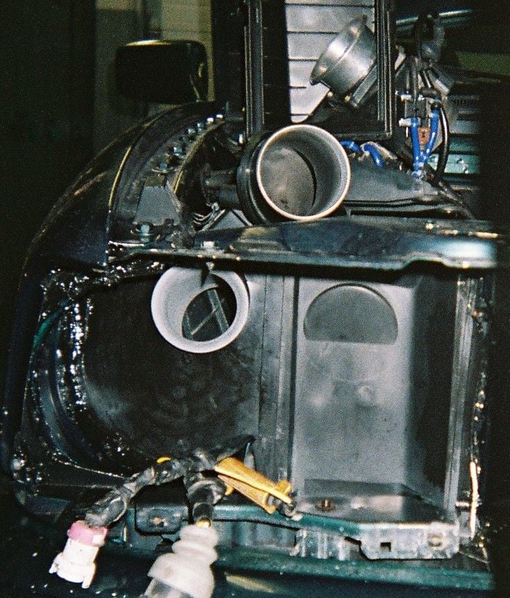
Sealed all the openings as per one of Mance's old CAI threads (see below). I used a temporary weather-stripping caulking (wear gloves!), tape & some plastic plugs, all available locally.The above photo shows why you best use gloves.
"...we went in and sealed all the inlet area up with silicone then placed some duct tape over all the holes and headlight adjusting ports in the top of the cold air intake side above the headlight. Once that was sealed up as best we could without removing the bumper we moved on to re-installing the air-box."
Also. have a look inside both the Snorkel & Noise-damper also; no their not painted grey, they have been carefully sanded straight and smooth. Inside the noise damper, you can see that I worked it from both ends to get maximum straightness and smoothness throughout.
Compare this bucket with all the gaps to be seen in the photo at "5. Filter-box / Bucket Seal:" two posts down.
Above the Noise-damper duct in the back-ground, you can see how the velocity-stack has been mounted through the air filter-box lid (actually right into the MAF housing), and this is how air now leaves the filter-box for the MAF, faster, with its' velocity increasing and more laminar. As well as helping air-flow, this also gives the sensor a much clearer signal and sooner.
Last edited by Lago Blue; 05-13-2020 at 03:26 AM. Reason: brevity
#10
AudiWorld Senior Member
Thread Starter
These are the 2 rubber grommets in the fender-well that receive the Filter-box mounting pins.
If they are missing, the Filter-box to Bucket seal cannot be properly maintained. I suspect these are lost during Filter-box installation, as all 3 Audi's I've owned had one missing.
Use "Simple Green" liquid detergent on the grommets' face & bore, then mounting the box is a little easier & the grommets are not pushed through into who knows where?

