When you click on links to various merchants on this site and make a purchase, this can result in this site earning a commission. Affiliate programs and affiliations include, but are not limited to, the eBay Partner Network.
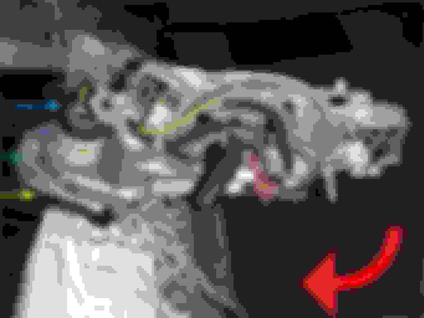
Hey everybody, I need some help. Please help me find a way to remove the spring (indicated by the violet arrow in the pictures) that holds the mirror.
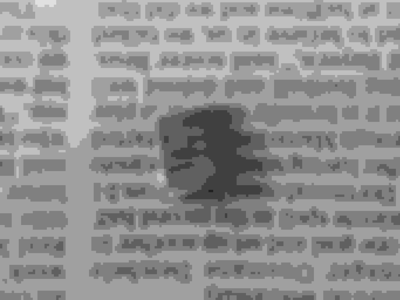
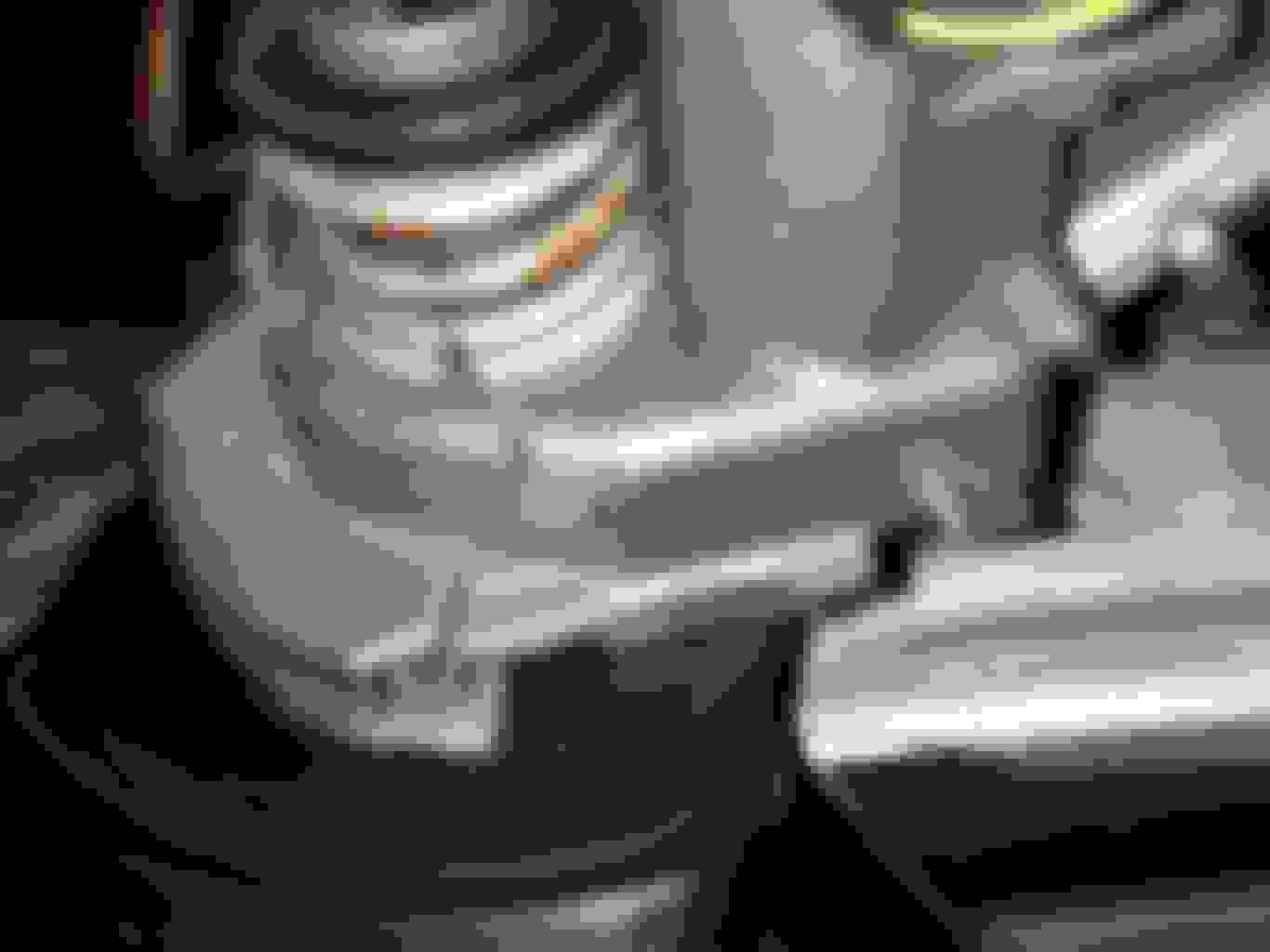
Details: This power folding mirror is on the right side of a 2014 Audi A4 B8. It is RHD and the mirror has heating and dimming, if it is relevant. It looks like it is held down by a circlip (indicated by the blue arrow), but there are no holes on the clip, to grip it for removal. There are 2, shallow, inward and outward indents on the clip, but I can't grip these. Under the circlip, is a washer with an upward lip,so even if I could grip the clip, I can't easily remove it without pushing the washer and spring down.
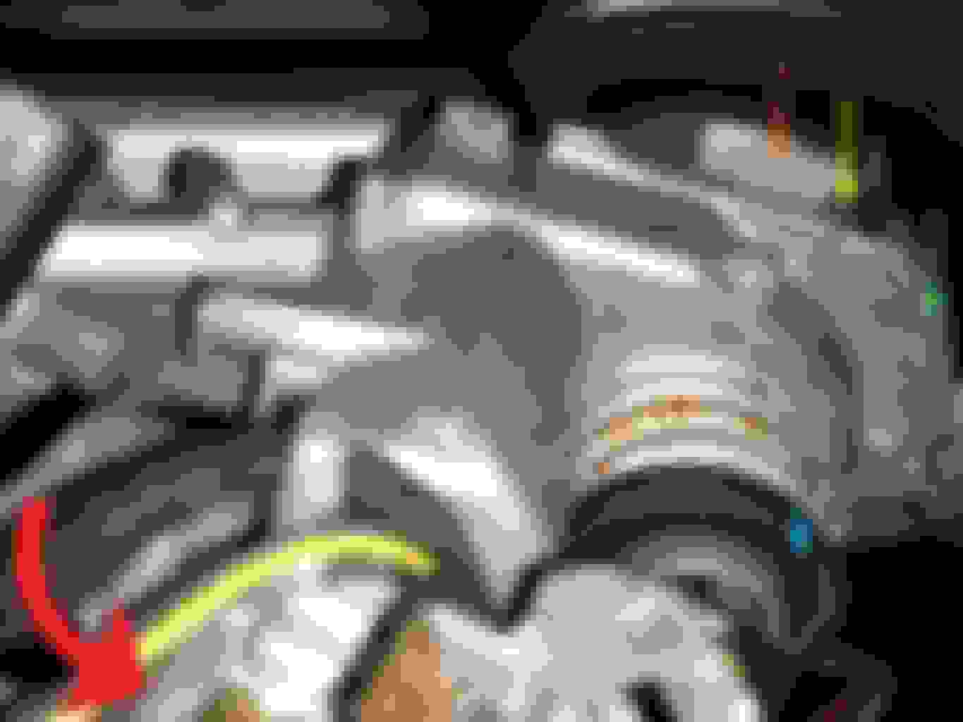
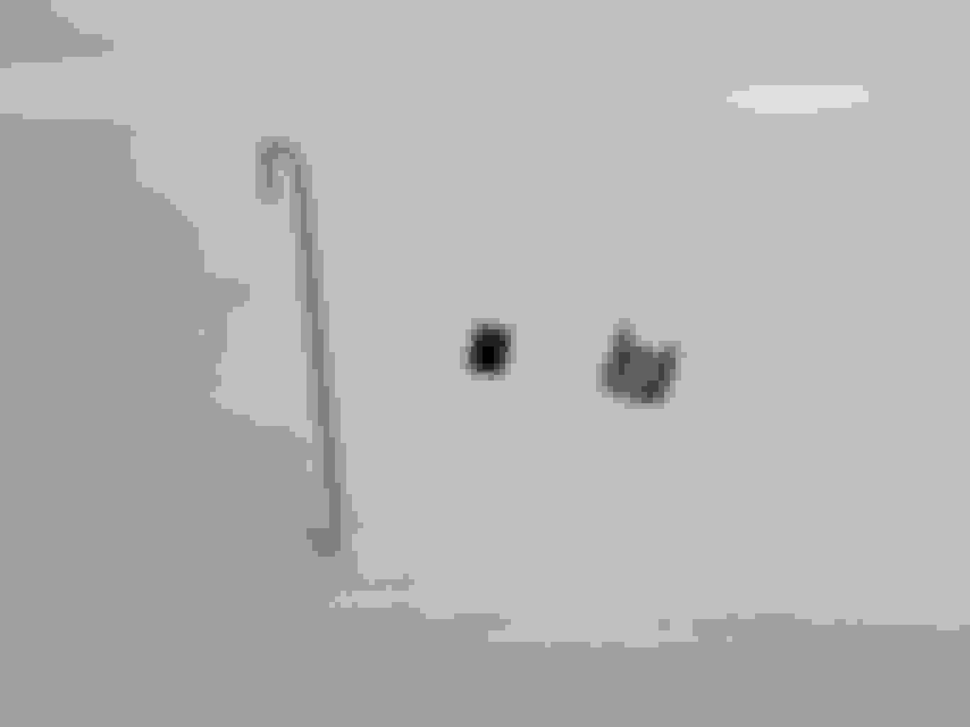
Background: I need to lift the aluminium frame to make a repair underneath. A small tab, (position indicated by the orange arrow) that stops the folding motion when the mirror is retracted, has broken off. Now the mirror folds in, much further than normal (as shown in picture 3), causing the painted mirror cover to touch the black part, and gouging the paint. I need to lift the aluminium frame off the base, to reliably re-attach the tab from where it broke.
Thelocation of the broken tab can be seen in picture (3) because, the frame has folded in beyond its normal stop position. If there was no defect, the tab would be underneath the cup / cap like part (indicated by the green arrow) of the aluminium frame. The part shown by the yellow arrow, would contact the tab and stop the mirror from folding further. I cannot glue it in the configuration shown in picture 3, because, then the mirror won't be able to deploy. The part indicated by the yellow arrow, would block it from the other side.Therefore, I need to lift it, to fix it.
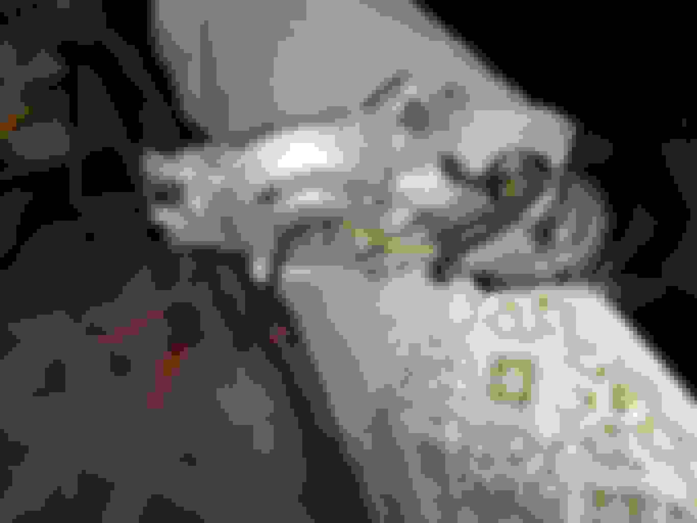
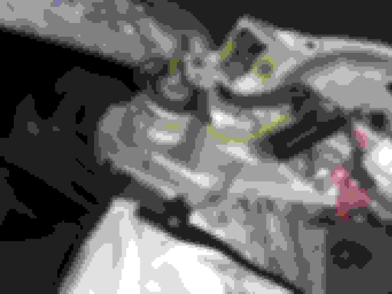
Picture description: Picture 1 shows the mirror frame in the normal deployed position. It retracts in the direction indicated by the red arrow. The camera is looking down from eye level and is facing forward.
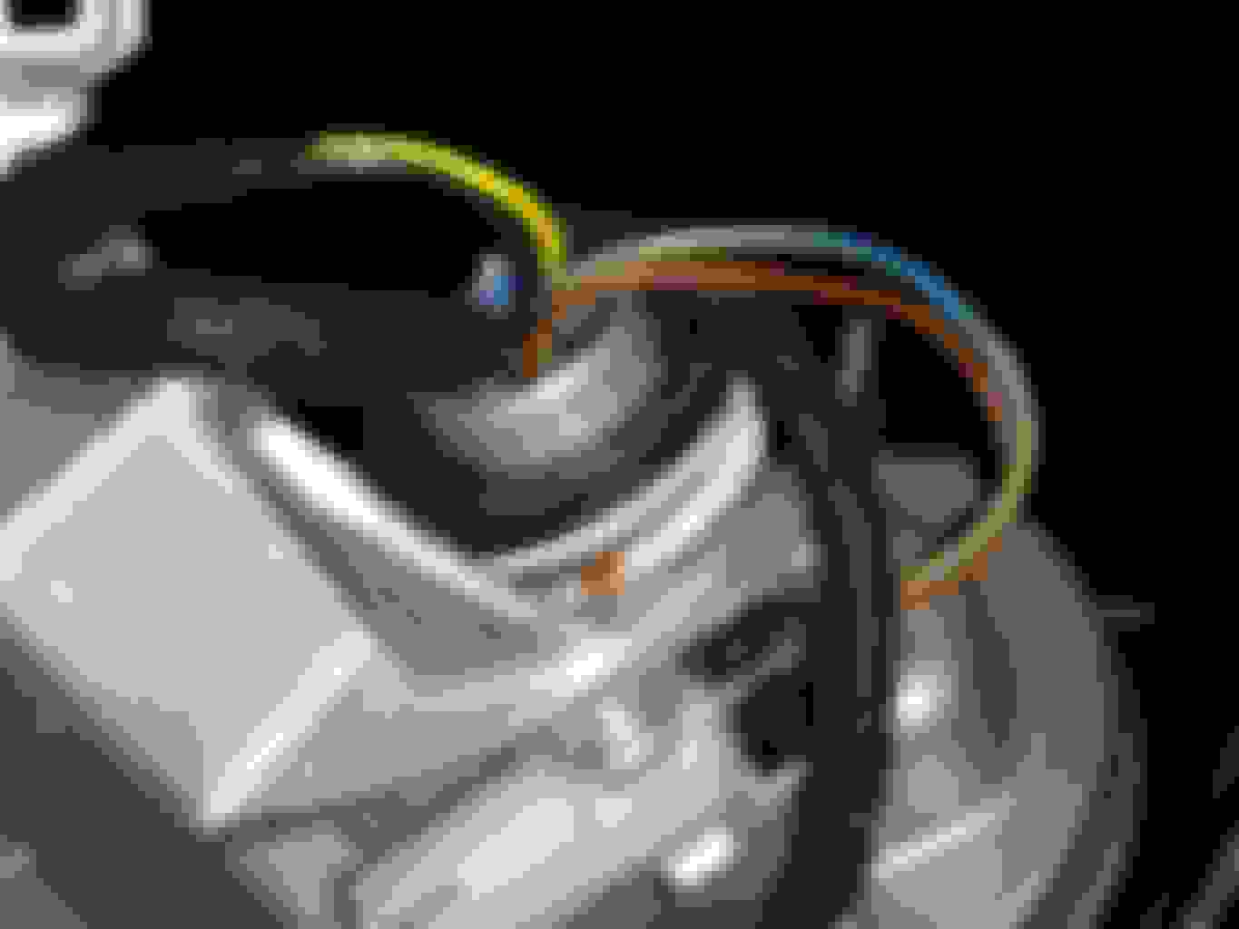
Picture 2 shows the spring and circlip up close. The mirror frame is in the normal deployed position, and the camera is at mirror height, facing backwards.
Picture 3 shows the mirror frame retracted beyond the normal limit, exposing the spot where the tab is supposed to be. The red arrow shows the direction in which the mirror will deploy. The camera is looking down in between the mirror frame and car body and is facing the side of the car. The front right window is seen in the top left.
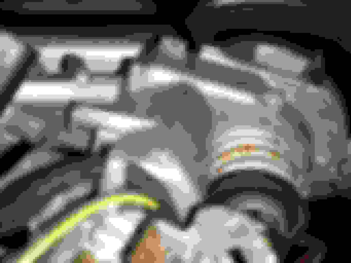
Picture 4 and 5 are same as above without the arrows, for clarity.
Picture 6 is of the assembly, taken from the internet.
Please help me with some info to lift the frame off, or suggest some other way to fix the mirror. Thank you for any help.
You will need to come up with a way to compress the spring so the circlip can be pushed off from its ends. Without this, you may be able to remove the spring but getting it back together will be the key. Is there any position of the mirror that takes pressure off the spring?
Hey, sorry forthe delay in posting back. I have been working on the problem andprogress was slow, since I was also busy with other work, and theprocess itself was a bit uncharted. I am happy to say that I havesuccessfully made the repair, for now. How durable the repair is,only time will tell. I could not get the spring to compress using thevarious ideas suggested to me. Needle nose pliers just slipped, cableties just snapped when pulled, wire also broke when twisted. I wasfirm on the decision that if I couldn’t compress it, I wouldn'tundo the clip. I will post more on what I did do, with pictures, in afew days, when I get a bit more time. I had to use epoxy, someshafts, and some drilling. The mirror works like before now.
First, I apologise for the delay in making this post. I got caught up in some other work, and I am the poster child for sloth.
The repair has been successfully completed. As to how long-lasting it is, only time, and extended use will tell. Here is what I did, in the unlikely event that someone else needs to make this repair themselves, or for those who are simply curious. Thanks to all who suggested ideas and information. Irrespective of whether the suggested methods worked or not, they were essential in the problem solving process that made this repair possible.
I had mainly asked for help in undoing the spring and clip that holds the main folding assembly together. A few ideas were suggested, but sadly none worked. The spring was just too strong, and I was just too scared. I guess this is what holds the mirror without vibration when the vehicle is in motion. First, I tried using needle nose pliers of two sizes to compress the spring, but they weren't small enough to really get in between the spring, and kept slipping. Next was GI wire. I threaded it through, and twisted the ends, but it just broke at the twist. Maybe stranded steel cable would have worked, but I did not have access to it. Finally, I threaded the thickest cable tie I could, and tried to tighten it, but it just snapped. Having failed to compress the spring, I was doubtful that I could reassemble it after removal. So, I decided to alter the plan, and make the repair with the assembly in place.
I typed out what I did, but then converted the entire description to read like instructions because it made the sentences much shorter. I could remove a lot of 'I did this's, 'then's, 'next's, and 'now's. Also, when words are changed from past to present tense, it saves a lot of letters.
The plan
Thankfully, due to the design of the assembly, with the stop tab broken, the mirror can be folded to a position where the damage is accessible. This can be seen in the earlier pictures. Drill two holes in the assembly, at either end of where the stop tab was. Cut two groves in the broken piece of the tab, at either end. Affix two small lengths of blind rivet mandrel in these groves, using epoxy adhesive. Affix the whole thing in place with epoxy.
Mask the surrounding paintwork and trim with something soft. I used bubble wrap. Roll down the window and lay a towel through to protect the door. Dropped or slipped tools and adhesive will cause damage.
The folding motor has a lot of torque and no pinch protection. So be very careful when it's moving. I cannot stress how powerful that motor is. It stops when it encounters significant resistance. The stop tabs provide this resistance, and that's how the folded and deployed positions are detected. But, if you manually give it this significant resistance at any point in its travel, it stops. This helps the repair process. I was stopping it at various positions, by pushing against it while folding or unfolding to asses the plan. The motor was powerful enough to knock me off balance if I hadn't taken a proper stance. Standing in between the door, with one hand on the fold switch, and one hand stopping this thing, is not easy.
Set the mirror to the folded position. It will move beyond its normal folded stop. Manually stop it before it contacts and damages the plastic trim. Use a steel nail and hammer to punch indents at the spots to be drilled, so that the bit won't slip. With the mirror folded, there is not enough clearance for a full-size drill. A rotary tool like a Dremel may work. I did not have one. Use the shaft of a craft knife as a drill bit extender. My bit kept slipping in the collet, but I managed to drilled through anyway. Use a 1 mm bit, followed by a 1.5, then a 2 mm bit, and drill to a depth of 3 mm. Increasing bit sizes are for two reasons. To get the bore at the exact spot. And, because an extension is used, the bit will wobble, and the bore will be oversized. I tried inserting the mandrel after the 1.5 mm bit, but it wouldn't fit, so the 2mm had to be used. After using the 2mm bit, the bore is a bit oversized, but the adhesive will fill the gap. The angle of the bore, has to match that of the original tab in both axes. Use a spray bottle with water to keep the temperature down, and to clear the shavings from the bore.
The black gasket material, which is seen at the base of the assembly, on top of the black trim, will obstruct the insertion of the stop tab. A small piece has to be cut off. The edge of this gasket is soft rubber, about 5mm all around, but the main part is hard plastic. Use a craft knife to poke and slice this, and cut out a small squarish portion. Keep the piece safe. Use a brush and dish soap to clean the bores, the cut gasket and surrounding area, to remove the road dirt, the drilled shavings and grease from the mechanism. A few washes may be required.
Use a hacksaw to cut grooves into the broken tab, at positions corresponding to the bores. Use a nail file and 400 grit sandpaper to shape the grooves to hold the mandrel snugly. Since all the work-pieces are aluminium, cutting and drilling is easy, and easy to overdo. So it's necessary to check progress at short intervals.
Cut a pair of blind rivet stainless steel mandrels, to a length of 11 mm. This is the clearance of the hole next to the assembly stopper (assembly stopper - yellow arrow). This clearance is important because, the stop tab has to be inserted through that hole. File the tab down to 8 mm. 8 mm of the mandrel will sit in the tab's groove and 3 mm will protrude. This 3mm will go into the holes drilled, and provide strength to the repair. At 8 mm, the tab will be tall enough to engage the stopper, and prevent the stopper from climbing over.
Use a two part epoxy adhesive to fix the mandrels to the tab. My adhesive box said it cures overnight, but 24 hours later, it hadn't hardened. It was raining continuously, so the humidity may have been slowing the curing process. There is a risk of the tab coming apart inside the assembly, so I decided to wait another 24 hours. Put it in a small metal box, and place on top of a fridge compressor. The heat will aid curing. Another 24 hours later, the epoxy had hardened enough.
I found a few rigid steel pins, about 5 cm long, angled at both ends. A friend of mine dropped his umbrella a few weeks before and damaged it. About 6-7 of these steel pins fell out of it. He gave them to me, saying I would find some use for it. Roro was right.
Use pliers to bend one end into a U shape. As an aid to insert and position the finished tab, stick the short side of the U to the edge of the tab, using a bit of cyanoacrylate adhesive (super-glue). This can be broken off, after the epoxy has set.
Mix and apply the epoxy in the bores and the base. Apply only to the base, not to the tab. This is to prevent accidentally getting the adhesive anywhere else during the fixing process. The adhesive is really strong once set, and can ruin the entire assembly if it gets some where inside.
Deploy the mirror, then fold it. While it is folding, manually stop it in a position just before its normal stop, so that the tab can be inserted through the hole and fixed into place. Holding the tab by the long steel pin, insert it through the gap and manoeuvre it into place. At this point, the pin broke off prematurely, but the tab was already in place. Slide another pair of steel pins though the hole to firmly keep the tab in place while the epoxy cures. One to hold it down, and one to prevent it from slanting.
Since it was raining continuously, I made an improvised heater to aid the curing. I used an incandescent bulb, an empty paint tin, an 80mm cooling fan and some newspaper. This set-up kept the repair spot at about 40 degrees C. Ask if anyone needs instructions to construct this.
After 24 hours of curing, remove the heater and the steel pins. I used the same pins to prod the adhesive and it seemed to have hardened. I poked the tab from several angles and tried to lever it. It seemed well fixed. For the actual test, fold the mirror. In my case, the assembly promptly sheared the tab and pushed it by just about a millimetre. The joint had failed. To be honest, I half expected it. The epoxy wasn't setting just right. I am not sure if it was the aluminium surface or the humidity or the grease creeping in. Somehow, even after washing, the surface around the hinge felt greasy after some time. The grease could have contaminated the adhesive. Or, maybe the texture of the surface feels greasy.
For a few minutes I lost hope. Then I thought, it's a good thing it failed like it did. This repair was bound to fail, and if the tab had broken off later, while in use, it would have fallen into the mechanism and got stuck, causing further damage. Plan B was now in effect.
Plan B
Well, plan B is a rather simple, all out attack, but with increased risk. No tab, just one longer mandrel at the leading edge, sitting in a deeper hole and glued in place.
Preparing the bore
Mask the surrounding paintwork as mentioned before. Since the motor had dislodged the tab already, my task was to lift it out of position and remove it, without dropping it into the assembly. I used the steel pins from earlier to accomplish this. I used the steel nail to scratch out the failed adhesive. Since it was not cured or adhered properly, it was not too difficult to remove. Re-drill the bore (the first one in the path of the assembly stopper) to a depth of 19 mm with the 2mm bit. Check the bore often to make sure the bit doesn't go through. The thickness of the assembly is unknown. The bit could damage any unknown mechanism or wiring beneath, or drill through the black outer trim. The bore has to be in the same vertical orientation as the original tab. If it slants in either axes, then the mandrel will obstruct the mechanism, or the stop position will be shifted. Wash and dry.
Preparing the mandrel
Since this lone mandrel had to bear all the load, I decided to use a mandrel from a rivet the next size up. This was about as thick as the original broken tab. It was a bit too big for the bore, so I ran it in the drill, with the rivet in the chuck, and used a file and an 80 grit sand paper to slightly thin it down. Check at regular intervals, until it is thin enough to snugly fit fully into the bore. Cut it to a length of 21 mm, and carve a notch at about 1 mm in from one end. Wash and dry.
Making the repair
Set the mirror to the faulty folded position as in picture 3. This time degrease the base, bore and mandrel using 99% iso-propyl alcohol. Rubbing alcohol will do, but without additives like cetrimide. Mix the 2 part epoxy adhesive in a clean, dry bottle cap. Again, apply the epoxy only in the bore, and not on the mandrel. Fill the other bore. Now insert the mandrel fully into the bore, with the non notched end first. Because the epoxy forms a seal, the mandrel will slide back out a bit, like a gas strut. Push the mandrel down, leaving the notched end outside the bore. This will leave 2 mm of the mandrel protruding. Hold the mandrel down with a steel pin, and deploy the mirror. The 2mm protrusion is short enough for the stop to pass over without obstruction. When the stop has passed over the mandrel, remove the steel pin. The mirror will reach the deployed position. Fold the mirror, but force stop it at a position just before its normal folded position, so that the mandrel is visible through the hole. The gas strut effect would have pushed the mandrel up. If not, use a steel pin to grip the notch on the mandrel and pull it up. The mandrel should be about 8 mm tall, or tall enough to not contact the assembly (green arrow). This leaves about 13 mm inside the bore.
Fold a strip of paper a few times and place it in between the mandrel and the stop (yellow arrow). Set the mirror to the folded position. The stop will pinch the paper, and clamp the mandrel in the required position. This prevents the mandrel from sliding down into the bore as the epoxy cures. The paper is to prevent the stop from bonding to the mandrel, since the mandrel will have picked up the epoxy when it was fully inserted into the bore. Use some epoxy to reattach the small piece of gasket that was cut off earlier. Let the epoxy cure. Use the heater to hasten the process.
After the curing period, deploy the mirror while holding the paper. Remove the paper without letting it fall into the assembly. Now fold the mirror to test the repair.
The mirror folded and managed to slightly flex the mandrel. That motor is powerful. Test about 5 more times. Every time the mandrel flexes a bit. This might dislodge the adhesive, but that's not a problem. The adhesive serves only a redundant role. The mandrel is snug enough in the bore that it won't slide down or slide out. If it does slide out, the cup (green arrow) will stop it. If it slides down the, adhesive inside the bore will stop it. The only point of failure, is when the mandrel will break from the fatigue caused by the flexing.
The black gasket material that can be seen at the base of the assembly, attached to the black trim was damaged. The edge was a bit chewed up, and the assembly was picking this up when folding open. Apply a bit of cyanoacrelate glue under the lip, and hold the rubber edge down with a piece of card for 30 seconds allowing it to set neatly. A 400 grit sandpaper was used to smoothen the edge and remove the whitening caused by the glue. The edges formed by the epoxy from attaching the small gasket bit was also sanded down. A bit of shoe polish was rubbed on with a cotton bud to remove the greying from the sanding.
To compensate for the removal of grease from repeated washings, spray a little motorcycle chain lubricant into the mechanism though the various holes and gaps in both folded and deployed positions. Now the repair is complete.
Can you confirm the motor location that does the folding and unfolding? I assume it is not the same motor that is used to move the actual mirror glass?
Can you confirm the motor location that does the folding and unfolding? I assume it is not the same motor that is used to move the actual mirror glass?
Sorry for the late reply. The folding motor is inside that housing next to the spring, on the folding part of the assembly. You can see wires going into it, near the base. The motor that does the mirror adjustment is the circular black one in the center, visible in picture 6.
 05-03-2017, 10:53 AM