Air mass sensor normal voltage?
#1
Hey there I have a 1988 90 quattro 10v. After a few weeks of the engine dying under load it finally gave me some codes to work with!!!
2233 -Reference voltage greater than 1 Volt. Check air mass sensor wiring
2232 -Output voltage too low or too high in relation to RPM. Check air mass sensor and wiring
I think it is actually an short in the wire somewhere because on some days the car will not hiccup at all. Some days it dies multiple times while driving.
So my question is what should the voltage be to the Air Mass Sensor? When I test the connector (on the cable) it is normally between 5v and 6v. If that is normal then I can go out and get a new sensor. If that is not then its time to rip apart my car to find a simple short or resistance in the wire.
If anyone knows the voltage off hand great. If not would anyone be willing to go check on their own car for me? (If you do, brownie points!!)
All help is appreciated!!!
#2

Ok so obviously I didn't get an answer to this question.....
After lots and lots and lots of research I found audis instructions to test the air sensor pot.
1988 Audi 90 Quattro L5-2309cc 2.3L SOHC (NG)
Vehicle Powertrain Man
Inspection Air Flow Sensor Potentiometer
nt Computers and Control Systems Air Flow Meter/Sensor» Testing a
NOTE: Do not remove the potentiometer from the air flow
sensor housing for any testing or inspection purposes. On the
CIS-E Ill injection systems,
systems. if the potentiometer is found to be faulty, the complete air flow sensor housing must be replace
the air flow sensor potentiometer is not a replaceable component. Unlike earlier CIS-E
a. Engine must be at normal operating temp (80 C/176 F).
b. Fault code display has been initiated
a Valve cover must be tight, and gasket in good condition
d. Oil dipstick must be sealed completely
e All electrical consumers (including A/C) must be switched OFF
f. Ignition timing must be correctly set.
g. lale mixture must be set to specification.
2. To gain access to the potentiometer harness plug
a. Remove the air duct to the oil cooler
b. Air filter housing from its lower bracket.
c. Disconnect the upper air flter housing and push the air flow sensor assembly away from the fender.
3. Test the resistance between terminal 3 of the harness plug and ground. Resistance should be less than 0.8 ohms
4. If resistance is not within specification, repair wiring
5. Check the between
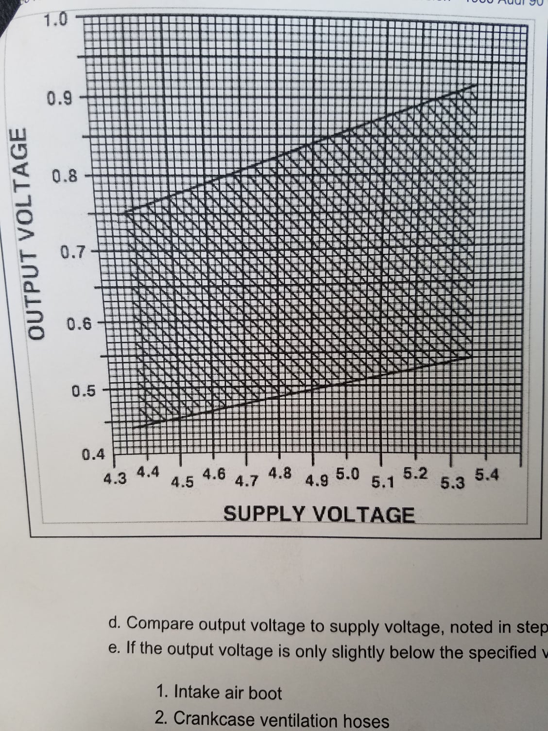
voltage between terminals 1 and 3 of the harness plug. With the ignition ON, the potentiometer supply
voltage should be 4.35-5.35vdc. Note the exact voltage
6. f voltage is not within specification, check wiring between the potentiometer harness plug and the injection control
unit plug. Pin designations are:
Potentiometer Plug Control unit plug
2
23
Resistance should be less than 0.8 ohms. Repair wiring as necessary.
8. Connect test harness Vw 1501, Fig. 8, between the potentiometer and the harness plug.
9. Connect a voltmeter to terminals 2 and 3 of the test harness
10. With the ignition ON, and the sensor plate in the REST position, output voltage should be 0-200 mV
11. To stabilize ignition timing for the test, insert the spare fuse into the fuel pump relay (do not remove until test is
completed). Idle speed should change slightly
a. With the engine running at idle, remove the harness plug from the Idle Control Valve. The engine speed must
increase.
b. Clamp one of the hoses from the idle control valve until engine speed decreases to 780-820 rpm. Ignition
timing should be 13 - 17 BTDC, adjust if necessary.
c. C
annect voltmeter to terminals 2 and 3 of the test harness, and note output voitage reading
d. Compare output voltage to supply voltage, noted in step 5, according to graph in Fig. 16
t voltage is only slightly below the specified values, check for air leaks in
1. Intake air boot
2.
Crankcase ventilation hoses
3. Charcoal canister hoses
Vacuum lines
. If the system has no
leaks, see "AIR FLOW SENSOR POTENTIOMETER" in "ADJUSTMENT
see
PROCEDURES"
In summary my car fit in all these parameters and drives even worse than it did before!! Fantastic. What a lovely problem to have.
Thread
Thread Starter
Forum
Replies
Last Post
AZSantorin
Audi 90 / 80 / Coupe quattro / Cabriolet
6
05-02-2003 11:57 AM
The Devil
Audi 90 / 80 / Coupe quattro / Cabriolet
10
04-21-2003 06:56 AM
DapperDan
A4 (B5 Platform) Discussion
4
09-09-2002 03:54 AM


